Table of Contents
Advertisement
Quick Links
ALL phases of this installation must comply with NATIONAL, STATE AND LOCAL CODES
IMPORTANT — This Document is customer property and is to remain with this unit. Please return to service information
pack upon completion of work.
These instructions do not cover all variations in
systems nor provide for every possible contingency to
be met in connection with installation. All phases of
this installation must comply with NATIONAL, STATE
AND LOCAL CODES. Should further information be
desired or should particular problems arise which are not
covered sufficiently for the purchaser's purposes, the matter
should be referred to your installing dealer or local distributor.
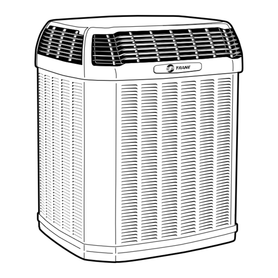
A. GENERAL
The following instructions cover 2TTX4 & 2TTX5; Condens-
ing Units.
NOTE:
The 2TTX4 outdoor units, except 2TTX4060, may be used
with indoor units equipped with Thermostatic Expansion
Valve or Accutron™ Flow Control Check Valve (F.C.C.V.)
assembly for refrigerant flow control only. The 2TTX5, and
2TTX4060 outdoor units must be used with indoor units
equipped with Thermostatic Expansion Valve only.
Check for transportation damage after unit is uncrated.
Report promptly, to the carrier, any damage found to the
unit.
To determine the electrical power requirements of the unit,
refer to the nameplate of the unit. The electrical power
available must agree with that listed on the nameplate.
B. LOCATION & PREPARATION
OF THE UNIT
1. When removing unit from the pallet, notice the tabs on
the basepan. Remove tabs by cutting with a sharp tool as
shown in Figure 2 (see page 2).
2. The unit should be set on a level support pad at least
as large as the unit base pan, such as a concrete slab.
If this is not the application used please reference
"XLi-APG**-EN" (* latest revision number).
3. The support pad must NOT be in direct contact with any
structure. Unit must be positioned a minimum of 12"
from any wall or surrounding shrubbery to insure
adequate airflow. Clearance must be provided in front
of control box (access panels) & any other side requiring
service access to meet National Electrical Code. Also,
the unit location must be far enough away from any
structure to prevent excess roof run-off water from
pouring directly on the unit. When choosing the location
of the unit(s), sound transmission through air and
Installer's Guide
Condensing Units
2TTX4018-060 & 2TTX5024-048
1
refrigerant lineset should be taken into consideration. It
is recommended to locate unit(s) away from areas
(bedrooms, etc.) where such sound will be objectionable.
4. The top discharge area must be unrestricted for at least
five (5) feet above the unit.
5. When the outdoor unit is mounted on a roof, be sure the
roof will support the unit's weight. Properly selected
isolation is recommended to prevent sound or vibration
transmission to the building structure.
6. The maximum length of refrigerant lines from outdoor to
indoor unit should NOT exceed sixty (60) feet.
7. If outdoor unit is mounted above the air handler, maxi-
mum lift should not exceed sixty (60) feet (suction line).
If air handler is mounted above condensing unit, maxi-
mum lift should not exceed sixty (60) feet (liquid line).
NOTE:
Refer to "Refrigerant Piping Software" Pub. No. 32-3312-0*,
and "Refrigerant Piping Manual" Pub. No. 32-3009-0* (the
position of the * denotes latest revision number).
8. Locate and install indoor coil or air handler in accor-
dance with instruction included with that unit.
18-AC54D1-4
5 FT. ABOVE UNIT-UNRESTRICTED
Advertisement
Table of Contents

Related Manuals for Trane 2TTX4018B


Summary of Contents for Trane 2TTX4018B
- Page 1 18-AC54D1-4 Installer’s Guide Condensing Units 2TTX4018-060 & 2TTX5024-048 ALL phases of this installation must comply with NATIONAL, STATE AND LOCAL CODES IMPORTANT — This Document is customer property and is to remain with this unit. Please return to service information pack upon completion of work.
-
Page 2: Installing Refrigerant Lines
Large diameter tubing will be very difficult to rebend AS SHIPPED once it has been shaped. FIELD SUPPLIED 3. Determine the best starting point for routing the refriger- LIQUID LINE ant tubing — INSIDE OR OUTSIDE THE STRUCTURE. 18-AC54D1-4 © 2009 Trane... - Page 3 Installer’s Guide 2. Attach appropriate hoses from manifold gauge to gas LIQUID LINE SERVICE VALVE and liquid line pressure taps. NOTE: Unnecessary switching of hoses can be avoided and complete evacuation of all lines leading to sealed system can be accomplished with manifold center hose and connecting branch hose to a cylinder of HCFC-22 and vacuum pump.
-
Page 4: Troubleshooting
Installer’s Guide 9. The liquid line shut-off valve can now be opened. Remove G. COMPRESSOR START UP shut-off valve cap. Fully insert hex wrench into the stem After all electrical wiring is complete, SET THE THERMO- and backout counterclockwise until valve stem just touches STAT SYSTEM SWITCH IN THE OFF POSITION SO rolled edge (approximately five [5] turns) observing COMPRESSOR WILL NOT RUN, and apply power by... -
Page 5: Typical Field Hook-Up Diagrams
Installer’s Guide TYPICAL FIELD HOOK-UP DIAGRAMS PRINTED FROM B152908 P02 PRINTED FROM B152901 P02 NOTE NOTE PRINTED FROM B152903 P02 PRINTED FROM B152907 P03 W2 present only on 2 stage W2 present only on 2 stage thermostat and furnace thermostat and furnace Notes: LEGEND 1. - Page 6 Installer’s Guide 2TTX4 & 2TTX5 OUTLINE DRAWING NOTE: ALL DIMENSIONS ARE IN MM (INCHES). MODELS BASE FIG. 2TTX4018B 1016 (40) 829 (32-5/8) 756 (29-3/4) 1/4 143 (5-5/8) 92 (3-5/8) 210 (8-1/4) 79 (3-1/8) 692 (27-1/4) 2TTX4024B 1016 (40) 829 (32-5/8)
-
Page 7: Mounting Hole Location
Installer’s Guide MOUNTING HOLE LOCATION NOTE: ALL DIMENSIONS ARE IN MM (INCHES). NOTE: For model base size, see table on page 6. From Dwg. D152637 Rev. 1 18-AC54D1-4... -
Page 8: Checkout Procedure
2 Check only necessary if heating unit is used for indoor section and wiring has been disturbed during installation of cooling equipment. 3 When applicable. Literature Order Number 02/09 File Number Supersedes Stocking Location Trane www.trane.com Trane has a policy of continuous product and product data improvement and it reserves the right to change design and specifications without notice.
Need help?
Do you have a question about the 2TTX4018B and is the answer not in the manual?
Questions and answers