Table of Contents
Advertisement
Quick Links
user manual
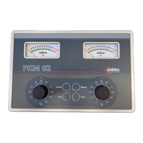
PKM 02
2-channel press force measuring device
TRsystems GmbH
D-75179 Pforzheim
Freiburger Straße 3
Phone: (+49) (0)7231/31520
Fax: (+49) (0)7231/315299
info@unidor.de
www.unidor.de
|
www.trsystems.de
© by TRsystems GmbH • 75179 Pforzheim • www.unidor.de • Tel.: (+49) (0)7231/3152 0
Page 1 of 19
Advertisement
Table of Contents

Subscribe to Our Youtube Channel
Related Manuals for unidor TRsystems PKM 02

Summary of Contents for unidor TRsystems PKM 02
- Page 1 PKM 02 2-channel press force measuring device TRsystems GmbH D-75179 Pforzheim Freiburger Straße 3 Phone: (+49) (0)7231/31520 Fax: (+49) (0)7231/315299 info@unidor.de www.unidor.de www.trsystems.de © by TRsystems GmbH • 75179 Pforzheim • www.unidor.de • Tel.: (+49) (0)7231/3152 0 Page 1 of 19...
- Page 2 © by unidor TRsystems GmbH D-75179 Pforzheim Freiburger Straße 3 Phone: (+49) (0)7231/31520 Fax: (+49) (0)7231/315299 info@unidor.de www.unidor.de www.trsystems.de Copyright protection This manual, including the images contained therein, are protected under copyright law. Third-party applications of this manual which violate copyright provisions are prohibited.
-
Page 3: Table Of Contents
user manual Table of contents Table of contents ..........................3 1 Change index ............................ 4 2 General ............................. 5 2.1 Scope of application ........................ 5 3 Additional safety notes ........................6 3.1 Definition of icons and notes ....................6 3.2 Supplement notes to the intended use ................... 6 3.3 Organizational measures ...................... -
Page 4: Change Index
user manual 1 Change index Change Date Index First edition 13. june 23 © by TRsystems GmbH • 75179 Pforzheim • www.unidor.de • Tel.: (+49) (0)7231/3152 0 Page 4 of 19... -
Page 5: General
2.1 Scope of application This user manual solely applies to the following product: PKM 02 Order number: 1050 300X 0000 The products are marked by attached nameplates and form part of a system. -
Page 6: Additional Safety Notes
user manual 3 Additional safety notes 3.1 Definition of icons and notes means that minor physical injury or property damage may occur if appropriate precautions are not taken. refers to important information and/or characteristics of and application advice for the product used. 3.2 Supplement notes to the intended use The system is designed to be used in Ethernet networks with a maximum speed of 100 Mbs for full- duplex operation specified in IEC 61158 as CPF2/2 (Communication Profile) -
Page 7: Technical Data
4 Technical data design PKM 02 display 2x pointer instrument 0-130% drag indicator operating system 2x potentiometer 0-100% 2x reset-/2x testbutton power supply 24V DC power consumption ca. 150W temperature range 0-60°C humidity max. 95% non condensing input impedance amplifier 1013 Ω... -
Page 8: Signals And Connection Diagram
On the rear of the device there are two M12 connection sockets (X75.1 and X75.2) to connect the piezo sensors. Outputs and power supply PKM 02 M12 socket X01 machine - stop. The relay is linked to the stop circuit of the machine. -
Page 9: Back Of The Device
user manual 7.2 Back of the device X75.2 sensor X74 analog input channel 2 output/reset X01 power supply X75.1sensor and stop output input channel 1 © by TRsystems GmbH • 75179 Pforzheim • www.unidor.de • Tel.: (+49) (0)7231/3152 0 Page 9 of 19... -
Page 10: Programming The Cutoff Values
user manual 8 Programming the cutoff values Turn the setting dial "max. press force" to the press force you require. Example: If you set the dial to 40%, a press with 1000 kN - i.e. 500 kN for each side - will automatically be switched off if a press force of >200 kN is reached. -
Page 11: View Of The Board
user manual 8.3.1 View of the board poti P1-3 setting comparator stage channel 1 poti P4-6 setting of comparator stage channel 2 factory settings jumper ME1 setting jumper ME2 setting jumper ME3 setting P302 trimmpoti channel 2 P302 SW402 SW402 amplifier stages channel 2 SW401 capacity levels integrator channel 2 SW401 P302 trimmpoti channel 2... -
Page 12: View Of The Board
user manual 8.3.1 View of the board LED 3 green LED 6 green +12V +7,5V LED 4 green -12V LED 5 green - 7,5V 8.4 Connections and settings on the board To adjust the capacitance and gain, the rear cover of the device must be removed. be removed. -
Page 13: Settings For Code Switches
user manual 8.4.1 Settings for code switches SW402 Codeswitches SW201(401) capacity (nF) Codeswitches SW202(402) amplification 71,8 11,12 65,0 11,08 61,8 11,03 55,0 10,96 49,8 10,93 43,0 10,84 39,8 10,76 SW401 33,0 10,64 38,8 10,48 SW202 32,0 10,27 28,8 10,07 22,0 9,67 16,8 9,51... -
Page 14: Jumper Und Dip-Switch Settings
user manual 8.4.2 jumper und DIP-switch settings jumper ME1-ME3 ME1+2 sampling latch channel 1+2: jumper left 2.2µF/right 10 µF ME3 reference voltage: jumper left Uref = 7.06V/right Uref = 6.79V DIP-switch SW1 switch 1-4 filter setting channel 1 either turn on only 1 or 2, or turn on none* F limit = 1KHz (33nF) (default 1+2= OFF) 1 F limit = 100Hz (220nF II 33nF) (1=ON, 2=OFF) 2 F limit = 355Hz (47nF II 33nF) (2=ON, 1=OFF) -
Page 15: Piezo Sensor Connection
user manual 8.5 Piezo sensor connection The piezo sensors delivered with the device are mounted to the press either on the pressing or drawing side (see diagram below). In order to protect the sensors, please place the protective caps over the sensors once the latter have been mounted and calibrated. The cables that connect the sensors to the device should not be disconnected or extended with either connectors or terminals (charge loss). -
Page 16: Initiation
user manual 8.6 Initiation • wire up the sensors and connecting cables • connect the distribution voltage • connect the press stop output to the press control • set the amplifier to basic position 3 using the code switch SW202 (SW402) •... -
Page 17: Dimensions
user manual 9 Dimensions © by TRsystems GmbH • 75179 Pforzheim • www.unidor.de • Tel.: (+49) (0)7231/3152 0 Page 17 of 19... - Page 18 user manual © by TRsystems GmbH • 75179 Pforzheim • www.unidor.de • Tel.: (+49) (0)7231/3152 0 Page 18 of 19...
-
Page 19: Ec Declaration Of Conformity
Manufacturer: TRsystems GmbH, System department Unidor Factory: Unidor, Freiburger Straße 3, D-75179 Pforzheim hereby confirm for the Product: PKM 02 Device type: Press Force Measuring Device Model name: PKM 02 compliance with the EC Directive 89/392/EEC and the following standards: ...
Need help?
Do you have a question about the PKM 02 and is the answer not in the manual?
Questions and answers