
Subscribe to Our Youtube Channel
Related Manuals for BOCI BLT4X

Summary of Contents for BOCI BLT4X
- Page 1 BOCI BLT4X Operating Instructions Original version Laser Cutting Head BLT 420-QBH/QD BLT440F-QBH/QD/Q+ BLT460F-QBH/QD/Q+ BOCI shanghai BOCI Automation Technology Co.,Ltd. Room 807, Lane 955, jianchuan Road, Minhang District, Shanghai, China.
- Page 2 BOCI Revision Directory Revision No. Revision Date Notes Version 2021/04/12 First Edition...
-
Page 3: Table Of Contents
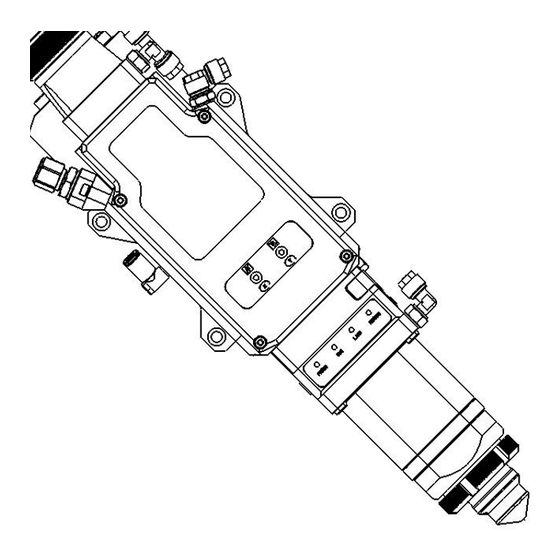
BOCI Table of contents 1. Prodcut Discription 4 1.1 Product view 4 1.2 Technical specifications 5 2. Assist gas Connectiosn 6 3. Water-cooling Connections 7 4. Eletrical Connections 8 5. Installation 10 Appendix A - Maintance 20 A1. Repalce Upper protective Glass 20 A2. - Page 4 BOCI 1. Product Discriptions 1.1 Prodcut View Water cooling outlet Fiber socket Upper Protective Lens 1 Upper Protective Lens 2 Water cooling inlet Cutting Gas interface Collimating unit Focusing unit Nozzle gas/ water-cooling interafce Lower protective lens 1 Lower protective lens 2 Figure 1-1: Cutting head view (structure and connections) Cutting Gas interface:...
-
Page 5: Technical Specifications
BOCI 1.2 Technical Specifications BLT440F BLT460F Cutting Head: BLT420 Laser Power: 15kw 20kw 1030-1090nm Laser Wavelength: Amplification Factor: Vertical Adjustment Range: ±35mm Horizontal Adjustment Range: Fiber interface Adapator: QBH/QD/Q+ Cutting Gas interface: Ø10, Max Pressure 25 bar(2.5 MPa). Gas Connections: Nozzel cooling gas interface: Ø6, Max pressuire 5 bar... - Page 6 BOCI 2. Gas Connections Cutting interface Nozzle cooling interface Figure 2.1: Gas connections Installation connections: cutting gas-1,nozzle cooling gas-2. Attention: The maximum cutting gas pressure is 25 bar (2.5 MPa). Cutting gas quality should meet the gas quality in line with ISO 8573-1: 2010 requirements: solid particles - class 2, water - class 4, oil - class 3.
-
Page 7: Water-Cooling Connections
BOCI 3. Water Cooling Connections Cooling Water Outlet Cooling Water inlet Figure 3.1: Water cooling connections Installation connections:Cooling water inlet 2A, cooling water outlet 1A. Attention: Water cooling pipe outter diameter 8mm, cooling water Max pressure 5 bar(0.5Mpa), Min flow rate 2.0L/min. -
Page 8: Eletrical Connections
BOCI 4. Eletrical connections 4.1 BLT 4X HypCut Version interface BCS210E Supply Power 220V Power supply cable Figure 4.1: BLT4X HypCut Connections Slave EtherCAT Station cable EtherCAT cable Attention: Main Station Only trained personnel can perform the above wiring. When connecting the cutting head to the BCS200E, the BCS200E must be powered off. - Page 9 BOCI 4.2 BLT 4X CypCut Version Power supply 24V DC Power Supply Cable Cable Cable Figure 4.2: BLT4X CypCut Connections Main Station CypCut Attention: Only trained personnel can perform the above wiring. When connecting the cutting head to the BC100,...
-
Page 10: Installation
BOCI 5. Cutting Head Installation During the installation process of the cutting head, dust or dirt may enter the cutting head accidentally, polluting the optical lens and affecting its functionalities. To prevent dust or dirt from entering the cutting head, refer to the following ways to install the cutting head: Figure 5.1: Cleaning Equipment... - Page 11 BOCI...
- Page 12 BOCI...
- Page 13 BOCI Lock Align with the red dotted- line Lock Align with the red dotted- line...
- Page 14 BOCI 7. Wind with tape The protection tape is used to seal the connector plugs. 3-5 times Use Protection tapes 3-5 times 3-5 times...
- Page 16 BOCI 9. Fixing the cutting head The laser head is fixed using four bore holes. When mounting the laser head to the machine,the user must take appropriate measures to prevent the laser head from vibrating. 10. Cooling Water leaking test Fill the pipes with water and check if there are any leaks.
- Page 17 BOCI 11. Cutting Head eletricial cables connections 11.1 BLT 4X HypCut Version Connect the POE cable to BCS200E. POE Cable 11.2 BLT 4X CypCut Versio n PWE Cable HC Capcitive Sensor Cable...
- Page 18 BOCI 12. Install ceramic nozzle holder and nozzle 12.1 Install ceramic nozzle holder and nozzle The nozzle and the nut must only be tightened manually (do not use any tools). Otherwise the ceramic part could be damaged. Additionally, make sure that the contact surfaces on...
- Page 19 BOCI 13. Gas Connection Connecting the cutting gas. Cutting gas nozzle cooling gas 14. Functionalities check Customer control systems can monitor the laserhead's operating status. A. Check the motor operating status. B. Check the sensor operating status. C. Check the capacitive distance controller sensor system operating status.
- Page 20 BOCI choose distance controller sensor type Axis con- figuration >> Distance .
- Page 21 BOCI...
-
Page 22: Appendix A - Maintance
BOCI Appendix A: Maintenance 1. Replace Upper protective lens 1 Upper protective lens door Upper protective lens drawer 1. Open upper protective lens door. 2. Pull the upper protective lens drawer out. 3. Remove the manifold seal ring and wave spring. - Page 23 BOCI 2. Replace lower protective lens 1 Lower protective lens door Lower protective lens drawer 1. Release the lens door by pushing the door latch. 2. Open the lens door. 3. Pull the drawer out. 4. Close the lens door during service to prevent contamination.
-
Page 24: A3. Replace Ceramic Nozzle Holder And Nozzle
BOCI 3. Replace Ceramic Nozzle Holder and Nozzle Ceramic Nozzle Holder Nozzle Manually tighten the nut. Do not use tools. Over-tight may cause damage. -
Page 25: A4. Beam Centering
BOCI 4. Beam Centering Verify all screws are tight after adjustment is complete X/Y Adjustment Screws Laser Beam Position Translucent Tape Pass Fail To Manually center the beam in the noozle: 1. Verify that the high power beam is disabled. -
Page 26: Appendix B - Mechanical Dimensions
BOCI Appendix B - Mechanical Dimensions 1. Installation Dimensions Through hole Mechanical Dimensions (e.g BLT420/440F/460F QBH) - Page 27 BOCI...
- Page 28 BOCI Specifications and designs are subject to change without any notice or obligation on the part of the manufacturer. January 2020 © BOCI CORPORATION BOCI...
Need help?
Do you have a question about the BLT4X and is the answer not in the manual?
Questions and answers