Table of Contents
Advertisement
Quick Links
Installation and Service Manual
This manual is effective for the installation and service of OK1 and OK2 systems
with 11" fans. See
Rev
Rev By
G
ME
H
ME
9980029073 Rev. H – 01/10/2023
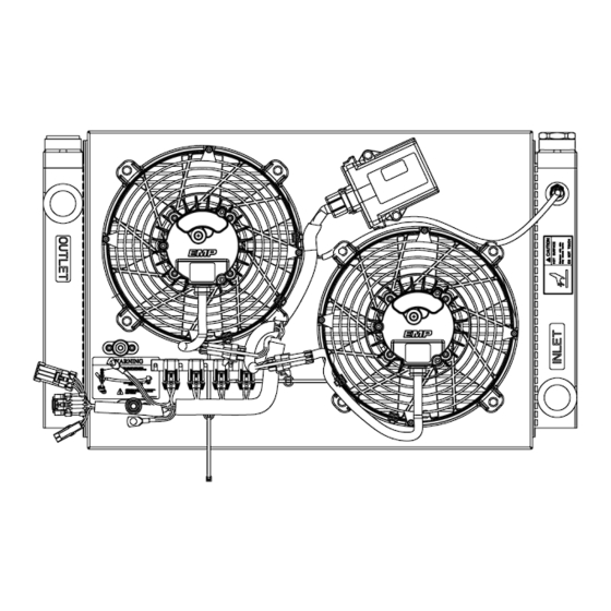
OK1/OK2 Oil Cooler Assembly
System Part Numbers
Date
5/19/22
Revisions
1/10/23
Revisions
for a complete list of systems.
Description of Change
© 2011 EMP, Inc.
Approved By
ECN7628
ECN8814
1
Advertisement
Chapters
Table of Contents

Related Manuals for EMP OK1

Summary of Contents for EMP OK1
- Page 1 Installation and Service Manual OK1/OK2 Oil Cooler Assembly This manual is effective for the installation and service of OK1 and OK2 systems with 11” fans. See System Part Numbers for a complete list of systems. Rev By Date Description of Change...
-
Page 2: Product Overview
Product Overview The EMP OK1/OK2 oil cooling systems are advanced thermal management products designed for applications requiring cooling of hydraulic oil, system oil, transmission oil, fluid or any other general cooling application using oil or a similar fluid. Benefits include lower energy consumption, reduced noise, individual fan diagnostics and improved temperature control. -
Page 3: Table Of Contents
Power/Ground Stud Replacement Kit (1370090014) – (If Required) ............26 Main Wire Harness ............................27 OK1 Harness Installation..........................28 OK2 Harness Installation..........................29 Heat Exchanger Replacement for OK1/OK2 ....................30 Shroud Replacement for OK1/OK2 ......................31 Fluid Thermistor ............................32 Service Tool Interface ..........................32 Appendix A –... -
Page 4: Introduction
Introduction Introduction Purpose The purpose of this document is to define the installation and service requirements of the OK1 and OK2 system part numbers that are listed in System Configurations. The requirements defined in this document must be followed in order to ensure proper operation and service life of OK1 and OK2 thermal systems. -
Page 5: About This Document
, calls attention to additional information about components and procedures NOTE discussed in the document. Definition of Terms CAN ....Controller area network. LED ....Light-emitting diode. EMP-Link ..EMP proprietary component to component communication network. µTMC .... EMP micro thermal management system controller. © 2011 EMP, Inc. -
Page 6: Product Safety Warnings
The safety messages in this document, in related manuals, and on the product are therefore not all inclusive. If a tool, procedure, work method, or operating technique that is not specifically recommended by EMP is used, you must satisfy yourself that it is safe for you and for others. You should ensure that the product will not be damaged or be made unsafe by the operation, maintenance, or repair procedures that you choose. -
Page 7: System Configurations
Product Identification The system product label, located on the upper left of the fan side on both OK1 and OK2 systems, lists the model code, system part number, and serial number of the system. The serial number can be used to obtain system configuration and all information necessary for component replacements. -
Page 8: System Part Numbers
System Configurations System Part Numbers OK1 and OK2 system configurations vary in voltage, control strategy, fan. 12 Volt Part 24 volt Part Type Control Cert Number Number 2020029049 2020029050 μTMC Pull 2020029051 2020029052 μTMC Push 2020029150* μTMC Push 2020029053 2020029054... -
Page 9: System Information
Reference Appendix B, Operation Manual μTMC System Controller for more information. For assistance with system calibrations or settings please contact EMP Technical Service at service@emp-corp.com and provide a serial number for the part in question. -
Page 10: Ok2
1 5/8-12 UN Maximum pressure drop in cooler 12 psi @ 30 mm /sec and 30 gpm Heat Exchanger Volume 0.8 gallons μTMC Controlled Systems Harness assembly 3170029068 Fan 1 address resistance: Open Fan 2 address resistance: Short © 2011 EMP, Inc. -
Page 11: Common Specifications And Operating Limits
12 fins/inch Maximum viscosity 2000 cSt NOTE: Higher fan speeds are available but conditions must be approved by EMP. NOTE: Higher flow rates can be used but fluid conditions must be reviewed. Wiring and Fusing Requirements Maximum continuous operating ambient temp 95 °C... -
Page 12: Heat Rejection
4000 rpm is the maximum speed setting on 12V OK1 and OK2. The 4000 rpm line represents the maximum performance achievable at 12V. 4600 rpm is the maximum speed setting on 24V OK1 and OK2. The 4600 rpm line represents the maximum performance achievable at 24V. -
Page 13: Μtmc Controlled Systems
If communication is disrupted, the fans will continue to run at a programmed default speed. A single fan part number is used for both locations on OK2 systems. The EMP-Link addresses used by the fans are set by reading resistance values from the harness. - Page 14 System Information OK1 harness 3170029067 OK1 Harness Connections NOTE: The harness is routed and secured to the system to prevent water damage, premature wear, and other system damage. When replacing the harness, take care to properly route and secure the system harness.
- Page 15 System Information OK2 Harness 3170029068 NOTE: Harnesses shipped after June 2021 remove a wire from Fan 1 and the EMP-Link connector. The removed wire does not impact the function of the system. OK2 Harness Connections NOTE: The harness is routed and secured to the system to prevent water damage, premature wear, and other system damage.
- Page 16 CAUTION: Ensure that all system power and ground connection points are torqued to EMP specifications to prevent system damage. Failure to follow specified torque requirements at any point of the vehicle system power and ground can result in loose connections which can damage electronic components on the cooling system and will void EMP warranty.
-
Page 17: Installation
Installation Installation Orientation OK1 and OK2 systems must be installed in an orientation that minimizes trapped air. It is preferred that the installation orientation prevent pooling of liquid on sealed surfaces. Preferred Orientations All connectors are properly oriented to prevent pooling of fluid on sealing surfaces. Tanks oriented to minimize chances of air entrapment. -
Page 18: Mounting
M8 or 5/16” fasteners are recommended for mounting the cooler. Eight fasteners should be used on the OK2 and six fasteners on the OK1. The recommended torque value is 20±2 ft-lbs. Due to variance in fasteners and threaded inserts, the mounting needs to be validated in each application. - Page 19 Installation NOTE: The mounting flange thickness on the OK1 and OK2 is 6mm. © 2011 EMP, Inc.
-
Page 20: Plumbing
This location must be carefully selected. See the table below for recommendations on fitting torque for the OK1 and OK2 inlet and outlet. Lubricate the O-ring lightly with the system fluid or compatible oil prior to installing the fitting. -
Page 21: Wiring And Fusing Recommendations
Fusing on the system protects the wiring on the system. If there is a long run of wire to the system, it is recommended that it be fused at the source also. This wire must be sized and fused for the full amperage capacity of the system. © 2011 EMP, Inc. -
Page 22: Software Calibration Options
24V system. 5000 and 5500 rpm options are available depending on the environmental conditions. Fan default speed (rpm) – The speed the fans will run if the fluid thermistor or EMP-Link communication is lost. It is typically set to equal the maximum speed. -
Page 23: Service Parts Replacement
232 size boots have a 1-1/2” diameter • opening. NOTE: Dielectric grease should be applied to completely cover metal (ring terminals, washers, nuts, and studs). It is acceptable for grease to be visible on the outside of the boot. OK2 Fuse Locations © 2011 EMP, Inc. -
Page 24: Fil11 Fan
Remove the fan mounting bolts (4 places). NOTE: The fan mounting bolts will be reused when installing the replacement fan. © 2011 EMP, Inc. -
Page 25: Μtmc System Controller
(See Connector Greasing). Once the new μTMC has been installed it must be configured for the vehicle using the EMP Service Tool unless the controller came pre- programmed with the proper calibration for the application. © 2011 EMP, Inc. -
Page 26: Power/Ground Stud Replacement Kit (1370090014) - (If Required)
If the decal that arrives with the replacement kit 1370090014 is different than what is on the assembly, replace the decal with the new one supplied. Configure the power and ground cables as shown on the decal and as shown in Power and Ground Stud Assembly Details. © 2011 EMP, Inc. -
Page 27: Main Wire Harness
Cut any cable ties attaching the harness to the shroud. Remove the main harness from each of the J-clips (OK1 only) by bending the J clips away from the fan shrouds they are attached to. -
Page 28: Ok1 Harness Installation
Service Parts Replacement OK1 Harness Installation Tie wrap the fan connection using EMP part number 3330036029 (11 inch black tie wrap). This section applies to temperature controlled OK1 The tie wrap must be positioned as shown. systems with a μTMC. -
Page 29: Ok2 Harness Installation
Connector Detail. to inserting into the μTMC (See Connector Tie wrap the fan connections using EMP part Greasing). Attach the μTMC branch of the number 3330036029 (11 inch black tie wrap). harness to fan #1 using the two clip mount tie... -
Page 30: Heat Exchanger Replacement For Ok1/Ok2
There are eight M8 x 25 mm fasteners that attach the fan shroud to the heat exchanger on OK2 and 4 M8 x 25 mm fasteners that attach the shroud to the heat exchanger on OK1. -
Page 31: Shroud Replacement For Ok1/Ok2
3/8” bulb seal over the top and bottom edges of the new shroud. If it is damaged, replace with a new seal. The bulb seal must be cut to a length of 17.75” for OK2 or 14.25” for OK1 to completely seal the shroud to the heat exchanger. -
Page 32: Fluid Thermistor
Follow the instructions for service tool installation and operation. This tool can be used for monitoring data, viewing diagnostic information, downloading new calibrations and downloading history data. (See Troubleshooting). When finished, unplug the data link adapter harness and re-install the sealed cap. OK1/OK2 Service Tool Connector © 2011 EMP, Inc. -
Page 33: Appendix A - Wiring Schematics
Appendix A – Wiring Schematics Appendix A – Wiring Schematics © 2011 EMP, Inc. - Page 34 Wiring Schematic – 3170029067 © 2011 EMP, Inc.
- Page 35 Wiring Schematic – 3170029068, Rev C and earlier © 2011 EMP, Inc.
-
Page 36: 3170029068, Rev D And Later
NOTE: Revision D Harnesses (shipped after June 2021) remove PWM IN 1/OUT 1 EMP-LINK/TACH +5V OUT BATTERY POS HS DRIVER a wire from Fan 1 (C01) and the EMP-Link connector (C07). The SIGNAL RETURN IGNITION GROUND BATT + removed wire does not impact the function of the system. -
Page 37: Appendix B - Operation Manual Μtmc System Controller
Appendix B Appendix B – Operation Manual μTMC System Controller © 2011 EMP, Inc. -
Page 38: Product Warranty Registration Form
Operation Manual μTMC System Controller Rev By Date Description of Change Approved By 6/22/20 New Release ECN5961 1/10/23 Revisions ECN8814 9970039169 Rev. B – 01/10/2023 © 2020 EMP, Inc. -
Page 39: Product Overview
Product Overview The μTMC is a system controller designed to take inputs from either PWM or physical sensors to control EMP components in a system. The system controller may be configured to receive a reverse command via a reverse button and have a diagnostic lamp. - Page 40 Connector Information ............................7 Mating Connector Information ........................7 Electrical Specifications and Requirements ....................... 8 Power Specification ............................8 Vehicle Ignition Enable Specification ......................8 Diagnostic Outputs ............................9 EMP Simple Service Tool ..........................9 General Troubleshooting ..........................10 © 2020 EMP, Inc.
-
Page 41: Introduction
If a tool, procedure, work method, or operating technique that is not specifically recommended by EMP is used, you must satisfy yourself that it is safe for you and for others. You should ensure that the product will not be damaged or be made unsafe by the operation, maintenance, or repair procedures that you choose. -
Page 42: About This Document
, calls attention to additional information about components and procedures NOTE discussed in the document. Definition of Terms μTMC ......Micro thermal management controller. EMP system controller. EMP-Link ....EMP proprietary serial communications. Ignition Enable ..Switched voltage supply used to activate the controller. OK ......EMP oil cooler. -
Page 43: Product Safety Warnings
The safety messages in this document, in related manuals, and on the product are therefore not all inclusive. If a tool, procedure, work method, or operating technique that is not specifically recommended by EMP is used, you must satisfy yourself that it is safe for you and for others. You should ensure that the product will not be damaged or be made unsafe by the operation, maintenance, or repair procedures that you choose. -
Page 44: Theory Of Operation
Interfaces with the μTMC include an ignition enable signal, thermistor interfaces to monitor temperature and an EMP-Link bus to interface with FIL11 fans, reverse push button and diagnostic lamp. A significant part of the μTMC functionality is to implement diagnostics which give indication of the overall status of the system and blink out error codes via the lamp on the system if a problem is detected and interface with the service tool. -
Page 45: Electrical Specifications And Requirements
Ignition enable must be separate from component power so that power remains on when ignition is switched off to enable controller shutdown processes. Vehicle Ignition Parameters Parameter Units 13.5 or 27 32.0 Ignition Current (13V) Ignition Current (27V) – Low (sleep) © 2020 EMP, Inc. -
Page 46: Diagnostic Outputs
Tool which is part of the EMP Service Suite available at no cost on the website. To use EMP Simple Service Tool, download and install the Service Suite software on your Windows PC. An interface device will be needed between the computer and the component. -
Page 47: General Troubleshooting
OK6 system. The OK6 system must be powered up and enabled to connect with the Simple Service Tool. Other μTMC controlled systems have a 3-pin diagnostic connector on the system harness. The system must be powered up and enabled to connect with the Simple Service Tool. © 2020 EMP, Inc. - Page 48 Product Warranty Registration Form Product Warranty Registration Form A standalone PDF of this registration form suitable for electronic submission is available in the Product Documentation section of the EMP website. Search for document number 9960039049. © 2011 EMP, Inc.
- Page 49 Individual Fan Controller EMP Alternator Oil Pump Other Electric Fan Cooling System Number of Fans Model Purchased Part Number Serial Number Installation Date Model, Serial Number, and Part Number are located on the EMP product label. 9960039049 Rev. G – 08/25/2022...
- Page 50 Vehicle Model Vehicle Model Year Vehicle Identification Number (VIN) Vehicle Miles/Hours at Installation If New System, Alternator Serial Number Notes Contact EMP Mail/Fax/E-mail completed registration forms to: EMP Advanced Development, LLC 2701 North 30th Street Escanaba, MI 49829 +1 (906) 789-7825 Fax: E-mail: warranty@emp-corp.com...
Need help?
Do you have a question about the OK1 and is the answer not in the manual?
Questions and answers