
Related Manuals for Berbel Downline Performance BKA 83 DLP


Summary of Contents for Berbel Downline Performance BKA 83 DLP
- Page 1 Hob extractor fan Downline Performance Operating and installation instructions for the models / BKA 83 DLP 6006619_a...
- Page 2 Document information Symbol clarification - text 1 Handling requirement Operating and installation instructions for: 2 Hob extractor fan BKA 83 DLP E07 2 Listing 2 Original instructions. , Reference to another point in this document 2 Part of the product. 2 Copyright protected.
-
Page 3: Table Of Contents
Table of contents Safety information ......4 Extraction operation .....33 Proper intended use . -
Page 4: Safety Information
Safety information Safety information Authorised target groups Electrical work only to be undertaken by qualified electricians. Requirements on qualified electricians: 2 Knowledge of the basics of electrics. Proper intended use 2 Knowledge of country-specific regulations and standards. The device is designed for normal domestic cooking, frying 2 Knowledge of the applicable safety regulations. -
Page 5: General Safety Instructions
Safety information General safety instructions . WARNING! Hazard through a disregard of the operating and installation instructions! This manual contains important information for the safe handling of the device. Separate reference is made to possible hazards. 1 Read through this manual thoroughly. 1 Follow the safety instructions in this manual. -
Page 6: Product Information
Product information Product information 2.2.1 Recirculated air mode Functional principle The filter filling in the recirculated air filter neutralises any smelly odours present. The odour-free, cleaned room air is fed back into the room. The humidity in the room can be reduced with the fresh air feed. -
Page 7: Product Overview
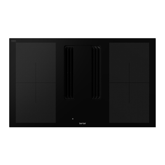
Product information Product overview Technical data Hob extractor fan BKA 83 DLP 400 V ~ / Connection voltage 50/60 Hz Total power 7630 W Power consumption of the hob 184.5 Wh/kg Power consumption of the fan 1x 230 W Hob width 830 mm Hob depth 505 mm... -
Page 8: Scope Of Delivery
Product information Scope of delivery 2.5.2 Accessory recirculating air kit DL BUF 2.5.1 Hob extractor fan A Powermover B Intake grate C Separator insert D Hob with fan housing and connection cable E Operating and installation instructions Depending on the operating mode, further accessories are required: 2 Recirculating air kit DL BUF –... -
Page 9: Accessory Recirculating Air Kit Dl Bur
Product information 2.5.3 Accessory recirculating air kit DL BUR 2.5.4 Accessory exhaust air kit DL A 150 mm conduit bend, 90° vertical B 150 mm elbow duct, 352 mm long C 150 mm shallow duct, 500 mm long D Height compensation plates, thickness 0.5/1.0/1.5/2.0 mm E 2x fastening base F 2x compression tape G Sealing strip... -
Page 10: Installation
Installation Installation Requirements for the installation location . WARNING! Safety instructions for installation Risk of death due to improper installation! Disregard of the ambient conditions can lead to hazardous . WARNING! situations, e.g. in the handling of electrical power or gas. 1 Make sure that the requirements for the installation Hazard through disregard of the installation instructions! location are complied with. -
Page 11: Requirements For Individual Operating Modes
Installation 2 The device must remain accessible at all times for Requirements for the exhaust air ducting (only for extracted air mode) maintenance work (e. g. with a removable rear panel or service cover). The space must be sufficiently large to allow for removal of the recirculated air filter. . -
Page 12: Installation Procedure
Installation Installation procedure If accessories (e.g. wall box, window contact switch) are required for the installation: Short overview: - Observe the instructions for the accessories. 1. Preparation for installation 1 Ensure that the accessories are correctly installed and 2. Unpack the device ready for connection. -
Page 13: Check The Dimensions
Installation 3.5.3 Check the dimensions Counter-top installation - To determine the dimensions of the hob, refer to the order documents. Flush installation ≥ 5 Width (a) 810 + 2 mm Cutaway Depth (b) 485 + 2 mm Work top Height (z) >... -
Page 14: Install The Hob
Installation 3.5.4 Install the hob . WARNING! Danger of injuries through improper handling! Installation of the device requires a great deal of physical exertion due to its size and weight. If the device falls down, serious injuries are possible. 1 Install the device with two persons. 1 Ensure stable footing during installation. - Page 15 Installation 1 Fit the Powermover on the intake grate. 1 Seal the cut surface of the work tip with suitable material (heat resistant to 75 °C – e.g. special paint, silicone rubber or cast resin). - For the material used, the worktop manufacturer’s instructions must be followed.
-
Page 16: Install Recirculating Air Kit Dl Buf
Installation 3.5.5 Install recirculating air kit DL BUF Installation variant for recirculated air mode with active carbon filter. - The instructions for installation variants with blow-out grate kit must be observed. 1 Align the recirculated air filter with the flap device to the access side. -
Page 17: Install Recirculating Air Kit Dl Bur
Installation 3.5.6 Install recirculating air kit DL BUR Installation variant for recirculated air mode with recirculated air filter permalyt. - The instructions for installation variants with blow-out grate kit must be observed. By trimming, it is possible to align the shallow duct with the spacing between the connections: 2 Between the fan‘s housing and circulating air bend with deep base cabinets. - Page 18 Installation 1 Adjust the recirculated air filter to the appropriate height: 1 Insert the shallow duct sections in the circulating air 2 Height-adjustability of at least 20 mm is necessary, bend. 1 Re-adjust the recirculated air filter to the appropriate in order to install the shallow duct sections afterwards.
-
Page 19: Install Exhaust Air Kit Dl
Installation 3.5.7 Install exhaust air kit DL Installation variant for extracted air mode. By trimming, it is possible to align the shallow duct with the spacing between the connections: 2 Between the fan housing and conduit bend with deep base cabinets. 2 Between the conduit bend and elbow duct with high base cabinets. -
Page 20: Connect Accessories
Installation . ATTENTION! 3.5.8 Connect accessories Risk of damage through incorrect connection! Available accessories are connected depending on the A mix-up of the control wires can result in damage to the installation situation: 2 Wall box electronics. 1 When connecting the control cable, ensure that the wires - Observe the instructions for the accessories. -
Page 21: Connect Light Source (Optional)
Installation 1 Observe the voltage specifications on the ratings plate. 3.5.9 Connect light source (optional) 1 Connect the hob to the on-site power supply. The The device enables the connection of an external light source, junction box is located on the underside of the device. which can be controlled via the device. -
Page 22: Check And Carry Out Commissioning
Installation 3.5.11 Check and carry out commissioning . ATTENTION! Risk of disruptions due to moisture in the device! If the device is moved from a cold environment into a hot one, condensation may form inside. 1 Wait about 2-3 hours before bringing the device into service. -
Page 23: Operation
Operation 2 If there is a drawer under the hob: Operation 2 Do not store flammable objects (e.g. spray cans). 2 Cutlery bins contained therein must be made of heat- resistant material. Safety instructions for operation 2 Only use the hob when the extraction is switched on. 2 The device must be switched off after use. -
Page 24: Cooking With Induction
Operation Cooking with induction Control panel In comparison to other types of hob (e.g. radiant heating The device is controlled via the control panel. The control or gas), there are a few peculiarities that must be observed panel is located centrally between the cooking zones. when using an induction hob. - Page 25 Operation The slider is located on the lower edge of the control panel, Button Function represented by a black box between the On/Off button and the Power button. Each box stands for a power level from 0 to 9 or for the corresponding number (e.g. for time setting). Power Simmer The slider can be used as follows:...
- Page 26 Operation The control panel has fields for display of specific values or Display Explanation settings: 2 Cooking zone 1 to 4 (selection and display, 1-digit in each The hob plates are locked. case) , “4.4.5 Locking function” (page 29). 2 Timer (only display, 2-digit) 2 Extraction (selection and display, 1-digit) Error Cooking zone indicators...
-
Page 27: Operation Of The Hob
Operation Operation of the hob Button Function . WARNING! 1 Choose a power level by tapping or swiping the slider. Risk of burns on hot parts! 2 The selected power level is displayed. The hob, cookware and the prepared foot can become very 2 The cooking zone is heated accordingly. -
Page 28: Automatic Rapid Heat-Up Function
Operation 4.4.2 Pause function Button Function Function for interruption of a cooking process with saved 1 Press the button. settings. Access takes place after pressing the menu button; 2 The device switches off. the corresponding symbol is displayed. 2 The run-on function starts with the appropriate setting. -
Page 29: Locking Function
Operation 4.4.5 Locking function 4.4.7 Grill function In order to prevent undesired changes to the settings of the Function for the use of grill plates, which are suitable for cooking zones, the control panel can be locked permanently. induction hobs, on the two left or the two right cooking Access takes place after pressing the menu button;... -
Page 30: Automatic Pot Recognition Function
Operation 4.4.10 Volume function Access takes place after pressing the menu button; the corresponding symbol is displayed. Function for adjusting the volume of acoustic signals. Access takes place after pressing the menu button; Button Function the corresponding symbol is displayed. 1 Press the slider at the position below the Button Function... -
Page 31: Timer Function
Operation 4.4.12 Timer function Switch off timer Function for adjusting an individual cooking time for each Button Function cooking zone from 1 to 99 minutes. 1 Select the programmed cooking zone via Switch on timer the corresponding display. Button Function 1 Press the timer display above the timer for 3 seconds. -
Page 32: Bridge Function
Operation 4.4.13 Bridge function 4.4.15 “Pot speed test” function Function for interconnection of the two left or the two right Function for determining whether the cookware is suitable cooking zones. The power/booster setting is not available for use with the induction hob. with use of the bridge function. -
Page 33: Extraction Operation
Operation Extraction operation 4.5.1 Operating modes There are three operating modes available for extraction by the device. The selected operating mode is shown in the Button Function display in the centre of the control panel. Extraction is selected with the corresponding button. -
Page 34: Run-On Function
Operation 4.5.2 Run-on function The device comes with a run-on function. If this function is used, the device will operate for a further 10 minutes at power setting after it has been switched off. In recirculated air mode, it is necessary to use the run-on function so that the device can remove the remaining odours. -
Page 35: Cleaning
Cleaning Cleaning Cleaning procedures If sugar, plastic, aluminium foil or similar materials come into contact with the hot hob, these materials must be removed Safety instructions for cleaning immediately: 1 Turn off the device. 1 Remove the materials while they are still hot. There is a . - Page 36 Cleaning The control panel can be locked for 20 seconds with the cleaning function in order to prevent unintended activation. , “4.4.4 Cleaning function” (page 28). 1 Clean the hob and the Powermover with a damp cloth or with special products for glass ceramic. 1 If spots or deposits are not removed, use a sponge or scraper with razor blade suitable for glass ceramic.
-
Page 37: Maintenance
Maintenance Maintenance Maintenance Replacing filter filling (with recirculated air mode) Odours are trapped in the filter filling in the recirculated air Safety instructions for maintenance filter. The odour-free, cleaned room air is fed back into the room. . WARNING! Recirculated air filters are maintenance-free for up to two Hazard through a disregard of the maintenance years. - Page 38 Maintenance Filter cartridge 1 Remove the filter cartridge. 1 Unscrew the screws on the bottom of the filter cartridge. Horizontal recirculated air filter (with installation variants with 1 Open the filter cartridge by removing the filter bottom. blow-out grate kit) 1 Empty the filter completely.
-
Page 39: Fault Rectification
Maintenance Fault rectification The control panels do not respond, the displays on all control panels show “L”. Possible faults are described below: Description of the fault. 2 Possible cause. 1 Remedy. The device does not work. 2 No power supply. 1 Check that the device is connected to the power supply. -
Page 40: Disassembly
Disassembly Disassembly Odours occur during operation. 2 The filter filling is used up. 1 Change the filter filling. . WARNING! , “Replacing filter filling (with recirculated air mode)” Risk of death due to electric shock! (page 37). Touching live parts can cause an electric shock, burns or death. -
Page 41: Disposal
Disposal Disposal Dispose of the device . ATTENTION! Dispose of packaging Risk of environmental damage due to improper disposal of the device! . ATTENTION! The device is subject to the European Directive 2012/19/EU and should not be disposed of with household waste. Risk of environmental damage due to improper disposal 1 Do not put the device into the normal household waste of the packaging! -
Page 42: Annex
BKA 83 DLP E07 with exhaust air kit DL Energy efficiency index (EEI) – – 43.8 EEI Hood Class – – FDE Hood – – 34.5 berbel BKA 83 DLP E07 FDE Hood Class – – LE Hood – – – LE Hood Class – –... -
Page 43: Contact
Annex Contact If you have any questions or suggestions, please select from the following options: Post: berbel Ablufttechnik GmbH Sandkampstraße 100 D-48432 Rheine Telephone: +49 (0) 5971 / 80 80 9 - 0 Mon to Thu 8:00 – 17:30 hrs and Fri 8:00 –... - Page 44 6006619_a 12.01.2023...
Need help?
Do you have a question about the Downline Performance BKA 83 DLP and is the answer not in the manual?
Questions and answers