Table of Contents

Related Manuals for Shield Shiel A-XT


Summary of Contents for Shield Shiel A-XT
- Page 1 Shiel A-XT Releasing Fire Control Panel ® Installation and Operation Manual Shield Fire, Safety and Security Ltd. Shield A-XT Releasing Fire Control Panel - Installation and Operation Manual SEXTCP-OM Revision E01.00 Issue Date: 5/2/2012...
- Page 2 Underwriters Laboratories (UL) File number (S 8485) Fire Alarm Equipment Shield Fire, Safety and Security Ltd. The model series of the Shield A-XT Releasing Fire Control Panel is suitable as follows: • Local Signaling Unit, Cross Zone and Releasing •...
- Page 3 This page intentionally left blank. Shield Fire, Safety and Security Ltd. Shield A-XT Releasing Fire Control Panel - Installation and Operation Manual SEXTCP-OM Revision E01.00...
- Page 4 Copyright © 2012 by Shield Fire, Safety and Security Ltd. All rights reserved. is a registered trademark of Shield Fire, Safety and Security Ltd. All other product names are the property of their respective owners. Shield Fire, Safety and Security Ltd.
-
Page 5: Table Of Contents
Field Terminals ............. 16 Shield Fire, Safety and Security Ltd. Shield A-XT Releasing Fire Control Panel - Installation and Operation Manual SEXTCP-OM... - Page 6 Reset ..............47 Shield Fire, Safety and Security Ltd. Shield A-XT Releasing Fire Control Panel - Installation and Operation Manual SEXTCP-OM...
- Page 7 Mode Select Key Switch ........... . 59 Shield Fire, Safety and Security Ltd. Shield A-XT Releasing Fire Control Panel - Installation and Operation Manual SEXTCP-OM...
- Page 8 Physical Specifications ............77 Shield Fire, Safety and Security Ltd. Shield A-XT Releasing Fire Control Panel - Installation and Operation Manual SEXTCP-OM...
- Page 9 Emergency Contact............112 Appendix E UL Compliance Label Appendix F UL 864 Permitted Configurations Shield Fire, Safety and Security Ltd. Shield A-XT Releasing Fire Control Panel - Installation and Operation Manual SEXTCP-OM Revision E01.00...
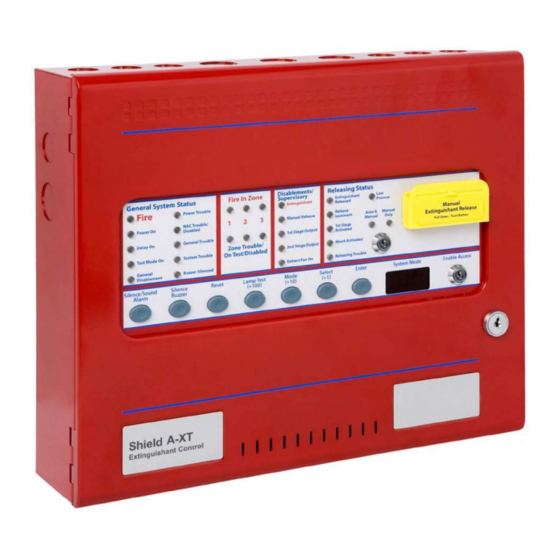
- Page 10 Introduction Section 1 Introduction Shield Figure 1-1 Shield A-XT Releasing Fire Control Panel Shield Fire, Safety and Security Ltd. Shield A-XT Releasing Fire Control Panel - Installation and Operation Manual SEXTCP-OM Revision E01.00 1 of 127...
-
Page 11: Introduction
Introduction Using This Manual The following sections provide instructions for installing, testing and troubleshooting the Shield A-XT Releasing Fire Control Panel: Section 1 Introduction provides document conventions, the technical help-line, repair and return information. Section 2 Overview provides a summary features of the Shield A-XT Releasing Fire Control Panel. -
Page 12: Document Conventions
Damaged Goods In the event of damage to equipment during transit or any defect in the quality of goods, the Buyer shall Notify Shield within seven days of delivery.The goods may then be returned to the Customer Service Department of Shield for repair, or replacement parts may be supplied (by arrangement). -
Page 13: Out Of Warranty Items
Returned equipment will be held awaiting authorisation for a period not exceeding 60 days from the date of quotation. After this period, Shield reserves the right to dispose of these items or return them. -
Page 14: Repair Warranties
Shield are under no liability if the repaired or replaced components are found to have failed due to fair wear and tear, willful damage, negligence, abnormal working conditions, misuse or alteration or repair without approval or failure to follow the sellers instructions. -
Page 15: Overview
Section 2 Overview The Shield A-XT Releasing Fire Control Panel is a co nventional re control panel and releasing system. The re control panel provides connections for Detection Zones, Noti cation Appliance Circuits (NACs), Releasing Circuits, Relay Outputs, Status Units and AUX 24 V power. - Page 16 TROUBLE RELAY. Interconnected status units Interconnected status units are provided with a limited set of indicators and functions compared with those provided on the Shield A-XT Releasing Fire Control Panel. Status unit functions are non-configurable on the fire control panel.
-
Page 17: Hardware Features
Overview Hardware Features The figure below illustrates hardware features of the Shield A-XT Releasing Fire Control Panel: Figure 2-2 Hardware Features FUSE AL FLT REMOTE DATA POWER NAC1 NAC2 ZONE 1 ZONE 2 ZONE 3 NAC3 1ST STAGE 2ND STAGE MODE MAN. -
Page 18: Internal Power Supply
Overview Internal Power Supply The internal power supply of the Shield A-XT Releasing Fire Control Panel meets UL 864, 9th edition and provides a 2 Amp, linear power-source for operating FACP functions as well as charging the standby batteries. The 2 Amp power supply operates 115 VAC and 230 VAC models of the Shield A-XT Releasing Fire Control Panel. -
Page 19: Panel Controls And Indicators
Overview Panel Controls and Indicators The fascia of the Shield A-XT Releasing Fire Control Panel is divided into sections for controls and indicators. The figure below illustrates controls and indicators of the Shield A-XT Releasing Fire Control Panel: Figure 2-3... - Page 20 Overview The table below describes upper controls of the Shield A-XT Releasing Fire Control Panel: Controls Modes Releasing Key-Switch Provides key-switch modes for automatic & manual or manual-only release Manual Extinguishant Provides manual release as a push button Release Central Controls...
-
Page 21: Indicators
Access Level 3. Indicators The front-panel of the Shield A-XT Releasing Fire Control Panel provides upper, central and lower indicators. Upper Indicators The figure below illustrates upper indicators of the Shield A-XT Releasing Fire Control Panel:... - Page 22 Overview The table below describes upper LED indicators of the Shield A-XT Releasing Fire Control Panel: General System Status LED Color Fire, NAC Output State Flashing = NACs Activated ON Continuous = NACs silenced OFF = Panel and NACs Reset...
- Page 23 (+10) (+1) The central indicator is the System Mode display of the Shield A-XT Releasing Fire Control Panel. The System Mode display contains three seven segment LEDs. Use this indicator to identify status conditions and to program configurations on the fire control panel.
- Page 24 Overview Lower Indicators The figure below illustrates the lower indicators of the Shield A-XT Releasing Fire Control Panel: Figure 2-9 Lower Indicators Mains Aux.24V Batt. Comms Earth Sys.Fuse NAC1 NAC2 NAC3 Exting. Abort Man.Rel. Mode Release Tell Trbl. Trbl. Fail Trbl.
-
Page 25: Field Terminals
Overview Field Terminals The figure below illustrates field terminals of the Shield A-XT Releasing Fire Control Panel: Figure 2-10 Field Terminals AL FLT REMOTE DATA POWER NAC1 NAC2 ZONE 1 ZONE 2 ZONE 3 NAC3 1ST STAGE 2ND STAGE MODE MAN. - Page 26 Relay contact is 1 Amp maximum with voltage free change-over FIRE RELAY Relay contact is 1 Amp maximum with voltage free change-over Shield Fire, Safety and Security Ltd. Shield A-XT Releasing Fire Control Panel - Installation and Operation Manual SEXTCP-OM Revision E01.00 17 of 127...
-
Page 27: General Installation Checklist
Installation Section 3 Installation This section provides instructions for connecting cables, mounting and testing the Shield A-XT Releasing Fire Control Panel for installation. Install this product in accordance with NFPA 72, the National Electrical Code and all local codes. General Installation Checklist To complete the installation: Create a plan for the fire alarm system and provide a checklist for installing the fire control panel. -
Page 28: Before You Begin
Ground straps must be worn by installers before handling electronic components to prevent this damage. Acquire the following items that are not included with the Shield A-XT Releasing Fire Control Panel, but may be required for the installation:... -
Page 29: Determining System Current Draw
Open the cabinet-door of the fire control panel using the door-lock-key. Disconnect the green ground cable from the cabinet-door. Remove the cabinet-door from the cabinet-box of the Shield A-XT Releasing Fire Control Panel. Remove the fascia from the cabinet-box. Remove the standby-batteries from the base of the cabinet-box. -
Page 30: Removing The Fascia
Installation Removing the Fascia Remove the fascia of the Shield A-XT Releasing Fire Control Panel prior to the mounting process to prevent damage to circuit board components. To remove the fascia from the cabinet-box of the Shield A-XT Releasing Fire Control Panel: Remove the two mounting-screws on the fascia that secure it to the cabinet-box. -
Page 31: Mounting
Installation Mounting Drill holes in the premises-wall to mount the cabinet-box of the Shield A-XT Releasing Fire Control Panel using mounting-hardware to secure it. Screws or bolts providing a minimum diameter of 0.2” (5 mm) must be used to mount the cabinet-box in three mounting positions. -
Page 32: Ac Cabling
Mon. AC Cabling Power cabling from the mains to the Shield A-XT Releasing Fire Control Panel must provide connections to branch circuits containing a 15 Amp fuse. Specify 14 AWG wiring for this connection. Power cabling must enter the at the back, top or left-side of the fire control panel cabinet through the cabinet-knockouts. -
Page 33: Standby-Battery Cabling
Battery standby-hours are dependant on battery capacity and loading of the FACP system. To install the replacement standby-batteries: Place standby-batteries at the bottom of the Shield A-XT Releasing Fire Control Panel cabinet. Connect the black battery-lead to the negative terminal of Battery 2. - Page 34 ( Black Cable ) 7 AH Battery 7 AH Battery The illustrated series connection above provides a standby voltage of 24 VDC required by the Shield A-XT Releasing Fire Control Panel. Shield Fire, Safety and Security Ltd. Shield A-XT Releasing Fire Control Panel - Installation and Operation Manual SEXTCP-OM Revision E01.00...
-
Page 35: Field Cabling
Zones of the Shield A-XT Releasing Fire Control Panel operate NFPA 72 Class B, Style C or NFPA 72, Class B, Style B. Style C devices provide trouble conditions for direct shorts and opens on zone loops. Style B devices provide alarm conditions for direct shorts and trouble conditions for opens on zone loops. - Page 36 ( - ) Supervised Inputs Supervised inputs of the Shield A-XT Releasing Fire Control Panel are Class B, Style C Initiating Device Cir- cuits (IDC). Supervised inputs include the field terminals of MAN RELEASE, ABORT, REL. PRES. SWITCH and LOW P.
-
Page 37: Remote Control Inputs
NAC devices are connected to these NAC outputs. NAC 1 and 2 NAC 1 and 2 of the Shield A-XT Releasing Fire Control Panel provide single and dual circuit synchronization for Zones 1 and 2 when operating with authorized synchronization modules. Single circuit synchronization provides synchronized NAC outputs on one channel of the Shield A-XT Releasing Fire Control Panel. - Page 38 Provide a connection from the NAC output to the NAC Extender PS-8 of Cooper Industries. During a trouble condition inputs open on the 1N1 terminals of the NAC Extender PS-8 providing a trouble condition on the Shield A-XT Releasing Fire Control Panel.
- Page 39 ZONE 3 TATUS UNITS iances of the Shield A-XT Releasing Fire Control Panel only. NAC 3 provides a special application output that is pulsed and continuous. The pulsed output of NAC 3 prevents it from operating strobe devices or s ynchronizing with devices on NAC 1 and NAC 2.
-
Page 40: Releasing Circuit
Maintain maximum current limits and loading. Releasing Circuit This section describes how to install releasing devices on the EXTING terminals of the Shield A-XT Releasing Fire Control Panel. The Shield A-XT Releasing Fire Control Panel operates releasing devices in compliance with Fire Protection Service Valves under UL 260, UL 429 and UL 429A. - Page 41 Installation The Shield A-XT Releasing Fire Control Panel operates only Shield authorized solenoid releasing valves. Reference Appendix B, Equipment List for a list of Authorized Releasing Valves. The figure below illustrates an example of the wiring for the releasing solenoid:...
-
Page 42: Relay Outputs
Fire Control Panel - Status Unit Terminals This section describes the Status Unit terminals of the Shield A-XT Releasing Fire Control Panel. Status Unit ter- minals of the Shield A-XT Releasing Fire Control Panel contain connections for Data and Power. The Data termi- nals provide RS485 communication. -
Page 43: Testing The Installation
To test the installation of the Shield A-XT Releasing Fire Control Panel: Disconnect wiring from the EXTING. terminals to the releasing solenoid before applying power from the source. -
Page 44: Troubleshooting
Troubleshoot the Shield A-XT Releasing Fire Control Panel when conflicts exist after installing or configuring. Monitor the lower fascia indicators of the fire control panel to determine the cause of the trouble condition. The lower indicators of the fascia are visible after opening the cabinet-door of the Shield A-XT Releasing Fire Control Panel. - Page 45 Can only be reset by pressing processor reset and W/DOG reset or powering down the fire control panel. Shield Fire, Safety and Security Ltd. Shield A-XT Releasing Fire Control Panel - Installation and Operation Manual SEXTCP-OM Revision E01.00 36 of 127...
- Page 46 Installation This page intentionally left blank. Shield Fire, Safety and Security Ltd. Shield A-XT Releasing Fire Control Panel - Installation and Operation Manual SEXTCP-OM Revision E01.00 37 of 127...
-
Page 47: Programming And Operating
The Shield A-XT Releasing Fire Control Panel can be configured for almost any installation requirement. Navi- gate the menu on the System Mode LED display using the Select and Enter buttons of the Shield A-XT Releasing Fire Control Panel. The System Mode LED, Select and Enter buttons are located in the center of the front-panel fascia. - Page 48 Missing flashing dot that the configuration indicates that the code is set. configuration code is not set. Shield Fire, Safety and Security Ltd. Shield A-XT Releasing Fire Control Panel - Installation and Operation Manual SEXTCP-OM Revision E01.00 39 of 127...
-
Page 49: Configuration Codes
Programming and Operating Configuration Codes Not all configuration codes of the Shield A-XT Releasing Fire Control Panel are authorized for operation under UL 864. Reference Appendix G, UL 864 Permitted Configurations for the list of authorized configuration codes of the Shield A-XT Releasing Fire Control Panel. - Page 50 Allows extinguishant output to be reset before countdown timer has reset during imminent phase. expired for installing and testing Shield Fire, Safety and Security Ltd. Shield A-XT Releasing Fire Control Panel - Installation and Operation Manual SEXTCP-OM Revision E01.00 41 of 127...
- Page 51 Any combination can be selected. Zone 2 operates through I.S. Barrier Zone 3 operates through I.S. Barrier Shield Fire, Safety and Security Ltd. Shield A-XT Releasing Fire Control Panel - Installation and Operation Manual SEXTCP-OM Revision E01.00 42 of 127...
- Page 52 29 minutes after discharge output has operated Panel can be reset 30 minutes after discharge output has operated Shield Fire, Safety and Security Ltd. Shield A-XT Releasing Fire Control Panel - Installation and Operation Manual SEXTCP-OM Revision E01.00 43 of 127...
-
Page 53: Operating The Fire Control Panel
300 seconds Operating the Fire Control Panel Access levels are provided for controls and programming on the Shield A-XT Releasing Fire Control Panel. Access Level 1 provides restricted controls, Access level 2 provides less restricted controls with limited programming and Access Level 3 provides unrestricted controls and programming. - Page 54 Programming and Operating Functions and Codes Functions and codes for operating the Shield A-XT Releasing Fire Control Panel in Access Level 2 are described below: Function Terminal Codes Description Test Zones ZONE 1 Select codes t1, t2 or t3 to place Zones 1, 2 or 3 in Test Mode.
-
Page 55: Control Operation
Programming and Operating Control Operation The table below describes control operation of the Shield A-XT Releasing Fire Control Panel: Controls Operation Terminate Release Press the Terminate Release button while in Access Level 3 to terminate the flow of extinguishant caused by a releasing event and reset the fire control panel. The flow of extinguishant can not be stopped using the reset button until after the extinguishant duration timer has elapsed. -
Page 56: Double Zone Fire Condition
Removal of a detector from it’s base or a trouble on any of the zone wiring will cause the Trouble LED and Zone Trouble LEDs to flash, indicating the zone in which the trouble has occurred. Shield Fire, Safety and Security Ltd. Shield A-XT Releasing Fire Control Panel - Installation and Operation Manual SEXTCP-OM Revision E01.00... -
Page 57: Nac Trouble
C2C (software version 1.2 and above only). Shield Fire, Safety and Security Ltd. Shield A-XT Releasing Fire Control Panel - Installation and Operation Manual SEXTCP-OM Revision E01.00... -
Page 58: Test Mode
To disable NAC outputs, press the mode button to select “db” on the seven segment display. Pressing enter will disable all NAC outputs and cause the General Disablement and NAC Trouble/ Disabled LEDs to light. Shield Fire, Safety and Security Ltd. Shield A-XT Releasing Fire Control Panel - Installation and Operation Manual SEXTCP-OM Revision E01.00... -
Page 59: Relay Operation
Reference additional disablement options in Functions and Codes of this section. Relay Operation The Shield A-XT Releasing Fire Control Panel provides volt free changeover relay contacts for local control and signalling. The relay contacts are rated for switching signalling circuits only and the maximum ratings should not be exceeded under any circumstances. -
Page 60: Calibrating The Releasing Circuit
Calibrating the Releasing Circuit Calibrate the releasing circuit by adjusting the EXTING. MON. potentiometer on the front-panel of the of the Shield A-XT Releasing Fire Control Panel. Adjust the EXTING MON setting to provide supervision of the “EXTING.”... -
Page 61: Maintenance And Repair
Cleaning the External Cabinet and Door Clean the external cabinet and door of the Shield A-XT Releasing Fire Control Panel with a damp cloth. Do not clean these surfaces with detergents or solvents. Do not permit water to enter the cabinet during the cleaning process. -
Page 62: Installing The Standby-Batteries
Replacing Fuses The Shield A-XT Releasing Fire Control Panel contains a battery fuse and an AC input fuse to protect it against circuit overloads. The battery fuse is a 3.0 Amp slow blow and the AC input fuse is a 1.6 Amp slow blow. -
Page 63: Ac Input Fuse
Install the replacement fuse in the upper-half of the fuse-housing. Connect the upper-half to the lower-half of the fuse-housing. Secure the fascia to the cabinet of the Shield A-XT Releasing Fire Control Panel using the two retaining-screws. Re-connect the red-lead of the recharging circuit to the positive terminal of the standby-batteries. -
Page 64: Replacing Cabinet Components
Confirm that 115 VAC or 230 VAC is turned-off at the power source. Install the replacement fuse in the terminal block housing. Re-connect cabling to the EXTING. terminals of the Shield A-XT Releasing Fire Control Panel. Close and lock the door of the Shield A-XT Releasing Fire Control Panel. -
Page 65: Supplementary Devices
Status Units are supervised for open-circuit, short-circuit and ground-fault conditions. Status Units are compatible with all models of the Shield A-XT Releasing Fire Control Panel. The Status Unit requires a data connection and 24 VDC to operate. Status Units can also be powered by the AUX 24V output or an auxiliary 24 VDC source that is listed for Fire Applications with Regulated and Power Limited Outputs. - Page 66 J2 Jumper removed from removed from this connected on this Status Unit Ancillary Board last Status Unit Shield Fire, Safety and Security Ltd. Shield A-XT Releasing Fire Control Panel - Installation and Operation Manual SEXTCP-OM Revision E01.00 57 of 127...
-
Page 67: Abort Connections
Supplementary Devices Abort Connections Abort connections of the Shield Status Unit are supervised for open-circuit, short-circuit and ground-fault conditions. Abort connections on the circuit board of the Status Unit are labeled Hold. Hold and Abort functions are identical. To provide supervised connections on the Abort terminals: Connect a 470 Ohm trigger-resistor, SEOLR-470 in series with one-leg of the normally open switch. -
Page 68: Mode Input
Therefore, all mode inputs must be inactive for the system to be in Automatic or Manual Mode. The system can include the Shield A-XT Releasing Fire Control Panel, IDCs, Status Units and Ancillary Boards. LED indicators on the front-panel of the Status Unit illuminate when the key-switch is in the “Automatic and Manual Only”... -
Page 69: Relay Contacts
MAN REL Relay The MAN REL relay operates when a manual release input occurs on the fire control panel. Shield Fire, Safety and Security Ltd. Shield A-XT Releasing Fire Control Panel - Installation and Operation Manual SEXTCP-OM Revision E01.00 60 of 127... -
Page 70: Connecting Power
UNIT, POWER terminals of the Shield A-XT Releasing Fire Control Panel. The total current obtained from connecting multiple Ancillary Boards and Status Units to the Shield A-XT Releasing Fire fire control panel must be below the maximum ratings of the AUX 24V or STATUS UNIT, POWER outputs. -
Page 71: Power Fault (Pf)
Abort indicators and the buzzer will sound. The panel display will show the status unit or ancillary boards that have the same address. Shield Fire, Safety and Security Ltd. Shield A-XT Releasing Fire Control Panel - Installation and Operation Manual SEXTCP-OM Revision E01.00... -
Page 72: Adding Status Units And Ancillary Boards
Disable the Write enable switch (push to the left). Disable the Enable controls key-switch. The panel should return to the normal, quiescent condition. Shield Fire, Safety and Security Ltd. Shield A-XT Releasing Fire Control Panel - Installation and Operation Manual SEXTCP-OM Revision E01.00 63 of 127... -
Page 73: Removing Status Units And Ancillary Boards
The seven segment display on the panel will show the number of the unit that is disconnected and all LEDs on the status unit that is disconnected will flash. Shield Fire, Safety and Security Ltd. Shield A-XT Releasing Fire Control Panel - Installation and Operation Manual SEXTCP-OM Revision E01.00... - Page 74 Supplementary Devices This page intentionally left blank. Shield Fire, Safety and Security Ltd. Shield A-XT Releasing Fire Control Panel - Installation and Operation Manual SEXTCP-OM Revision E01.00 65 of 127...
-
Page 75: Specifications
Specifications Appendix A Specifications This appendix provides electrical and environmental specifications for the Shield A-XT Releasing Fire Control Panel with Releasing. Electrical AC Line Connection Terminals Description Voltage AC Line 115 VAC @ 50 / 60Hz (Supervised) 230 VAC @ 50 / 60Hz (Supervised) - Page 76 Maximum Current Draw The maximum current draw of the Shield A-XT Releasing Fire Control Panel cannot exceed 2.0 A. Outputs of the fire control panel can be loaded with any combination of currents as long as the total current does not exceed 2.0 A.
-
Page 77: Rechargeable Battery Circuit
236 mA. Standby and alarm current of the Shield A-XT Releasing Fire Control Panel can include all or part of the following loads:... -
Page 78: Ground Trouble Indication
Specifications NAC outputs on the Shield A-XT Releasing Fire Control Panel are load dependant and are limited to a maximum current load of 500 mA. The releasing output on the Shield A-XT Releasing Fire Control Panel is load dependant and is limited to a maximum current load of 1000 mA. - Page 79 Battery leads are provided in the cabinet for recharging the standby-batteries. One end of the battery leads are permanently connected to the power supply of the Shield A-XT Releasing Fire Control Panel. The opposite end of the battery leads connect to terminals of the standby-batteries.
-
Page 80: Initiating Device Circuit (Idc) Ratings
Fused: Electronic 1.1 A Supervision: Voltage reversing DC Short Circuit Threshold: 130 Ohms +/- 20% Maximum line-voltage-drop: 2 VDC Shield Fire, Safety and Security Ltd. Shield A-XT Releasing Fire Control Panel - Installation and Operation Manual SEXTCP-OM Revision E01.00 71 of 127... -
Page 81: Releasing Device Circuit
Low Press. Switch Monitored Input EOL: 6.8K Ohm, SEOLR-6.8 +/- 5% resistor supplied in terminals, activation impedance: 470 Ohms Shield Fire, Safety and Security Ltd. Shield A-XT Releasing Fire Control Panel - Installation and Operation Manual SEXTCP-OM Revision E01.00 72 of 127... - Page 82 (NC), (C) and (NO) Relay Function: Common 30 VDC @ 1A maximum, volt free change over contact Shield Fire, Safety and Security Ltd. Shield A-XT Releasing Fire Control Panel - Installation and Operation Manual SEXTCP-OM Revision E01.00 73 of 127...
-
Page 83: Aux 24V
18 - 28 VDC Special Application Output, 500 mA maximum Power Output Circuits The Shield A-XT Releasing Fire Control Panel provides power output circuits on NAC 1, NAC 2, NAC 3, AUX 24V, STATUS UNITS, POWER and the EXTING terminals. -
Page 84: Status Unit Terminals
Connect Zone cabling using a minimum of 1 mm cross sectional area. Shield Fire, Safety and Security Ltd. Shield A-XT Releasing Fire Control Panel - Installation and Operation Manual SEXTCP-OM Revision E01.00... -
Page 85: Supplementary Devices
30 VDC @ 1A maximum, volt free change over contact Power Fault (PF) No Connect (NC) terminal Shield Fire, Safety and Security Ltd. Shield A-XT Releasing Fire Control Panel - Installation and Operation Manual SEXTCP-OM Revision E01.00 76 of 127... -
Page 86: Operating Environment
Maximum Screw Diameter: 0.2" (5 mm) screws This fire control panel is designed for indoor use only. Shield Fire, Safety and Security Ltd. Shield A-XT Releasing Fire Control Panel - Installation and Operation Manual SEXTCP-OM Revision E01.00 77 of 127... -
Page 87: Appendix B Calculations
Current loading calculations do not include the combined IDC currents of the Shield A-XT Releasing Fire Control Panel. These combined IDC currents are negligible in comparison to fire control panel, ancillary device and NAC currents of the Shield A-XT Releasing Fire Control Panel and are therefore excluded from the current loading calculation. -
Page 88: Current-Loading
Current-Loading Current-loading of the Shield A-XT Releasing Fire Control Panel is limited to the 2.0 Amp capacity of the power supply and the 7 AH capacity of the standby-batteries. The standby-batteries can provide an operating duration of twenty-four hours followed by five minutes of alarm when the standby current does not exceed 236 mA. -
Page 89: Nac Wiring Length
= [ ( 0.209 + 0.209 + 0.209 + 16 / 10K ) ] A = ( 0.627 + 0.0016 ) A = 0.6286 A total Shield Fire, Safety and Security Ltd. Shield A-XT Releasing Fire Control Panel - Installation and Operation Manual SEXTCP-OM Revision E01.00 80 of 127... - Page 90 = 1/2 [ ( 4.4 / 0.6286 ) / ( 0.006385 Ohms / FT ) ] = 548 FT Shield Fire, Safety and Security Ltd. Shield A-XT Releasing Fire Control Panel - Installation and Operation Manual SEXTCP-OM Revision E01.00 81 of 127...
- Page 91 Example circuit identifies wire measured across outmin length for two conductor cable NAC1 terminals NAC1 NAC2 Fire In Zon Shield Fire, Safety and Security Ltd. Shield A-XT Releasing Fire Control Panel - Installation and Operation Manual SEXTCP-OM Revision E01.00 82 of 127...
-
Page 92: Releasing-Circuit Wiring Length
65% nominal UL 429 specifies that the SRV operate a minimum voltage 65% below the nominal rating. Shield Fire, Safety and Security Ltd. Shield A-XT Releasing Fire Control Panel - Installation and Operation Manual SEXTCP-OM Revision E01.00 83 of 127... - Page 93 The circuit connection is provided with 18 AWG solid copper wire. • The maximum power rating for the SRV (WSRV ) is 9.11 Watts. • The nominal output-voltage for the Shield A-XT Releasing Fire Control Panel (Vout ) is 24 VDC. nominal • The nominal operating-voltage for the SRV (VSRV ) is 24 VDC.
- Page 94 Refer to the manufacturer specifications of the SRV for the maximum power rating (WSRV = 9.11 W / 15.6 VDC Imax = 584 mA Shield Fire, Safety and Security Ltd. Shield A-XT Releasing Fire Control Panel - Installation and Operation Manual SEXTCP-OM Revision E01.00 85 of 127...
- Page 95 SRV terminals. opmin EOL Diode 1N504-G, SEOLD-504 band end to ( + ) Shield Fire, Safety and Security Ltd. Shield A-XT Releasing Fire Control Panel - Installation and Operation Manual SEXTCP-OM Revision E01.00 86 of 127...
- Page 96 Calculations This page intentionally left blank. Shield Fire, Safety and Security Ltd. Shield A-XT Releasing Fire Control Panel - Installation and Operation Manual SEXTCP-OM Revision E01.00 87 of 127...
-
Page 97: Wiring Diagram
This wiring diagram describes circuit connections for all models of the shield A-XT Releasing Fire Control Panel. Shield Fire, Safety and Security Ltd. Shield A-XT Releasing Fire Control Panel - Installation and Operation Manual SEXTCP-OM Revision E01.00 88 of 127... - Page 98 AC input. Related Documentation The following documents shall be used to provide additional information for installing and operating the Shield A-XT Releasing Fire Control Panel: ■ Installation and Operations Manual, SEXTCP-OM, Rev. E01.XX ■ Operating Instructions, SEXTCP-OI, Rev. P01.XX ■...
- Page 99 90 of 127...
- Page 100 Wiring Diagram Shield Fire, Safety and Security Ltd. Shield A-XT Releasing Fire Control Panel - Installation and Operation Manual SEXTCP-OM Revision E01.00 91 of 127...
- Page 101 Wiring Diagram Shield Fire, Safety and Security Ltd. Shield A-XT Releasing Fire Control Panel - Installation and Operation Manual SEXTCP-OM Revision E01.00 92 of 127...
- Page 102 ■ MAN RELEASE ■ ABORT ■ REL. PRES. SWITCH ■ EXTING ■ LOWP. SWITCH ■ DATA, STATUS UNITS Shield Fire, Safety and Security Ltd. Shield A-XT Releasing Fire Control Panel - Installation and Operation Manual SEXTCP-OM Revision E01.00 93 of 127...
- Page 103 Wiring Diagram Shield Fire, Safety and Security Ltd. Shield A-XT Releasing Fire Control Panel - Installation and Operation Manual SEXTCP-OM Revision E01.00 94 of 127...
- Page 104 Wiring Diagram Shield Fire, Safety and Security Ltd. Shield A-XT Releasing Fire Control Panel - Installation and Operation Manual SEXTCP-OM Revision E01.00 95 of 127...
- Page 105 Wiring Diagram Shield Fire, Safety and Security Ltd. Shield A-XT Releasing Fire Control Panel - Installation and Operation Manual SEXTCP-OM Revision E01.00 96 of 127...
- Page 106 Wiring Diagram Shield Fire, Safety and Security Ltd. Shield A-XT Releasing Fire Control Panel - Installation and Operation Manual SEXTCP-OM Revision E01.00 97 of 127...
- Page 107 Wiring Diagram Shield Fire, Safety and Security Ltd. Shield A-XT Releasing Fire Control Panel - Installation and Operation Manual SEXTCP-OM Revision E01.00 98 of 127...
- Page 108 Wiring Diagram Shield Fire, Safety and Security Ltd. Shield A-XT Releasing Fire Control Panel - Installation and Operation Manual SEXTCP-OM Revision E01.00 99 of 127...
- Page 109 500 mA threshold of each NAC output. Security Ltd. Security Ltd. Shield Fire, Safety and Security Ltd. Shield A-XT Releasing Fire Control Panel - Installation and Operation Manual SEXTCP-OM Revision E01.00 100 of 127...
- Page 110 Wiring Diagram Shield Fire, Safety and Security Ltd. Shield A-XT Releasing Fire Control Panel - Installation and Operation Manual SEXTCP-OM Revision E01.00 101 of 127...
- Page 111 Wiring Diagram Shield Fire, Safety and Security Ltd. Shield A-XT Releasing Fire Control Panel - Installation and Operation Manual SEXTCP-OM Revision E01.00 102 of 127...
- Page 112 Wiring Diagram Shield Fire, Safety and Security Ltd. Shield A-XT Releasing Fire Control Panel - Installation and Operation Manual SEXTCP-OM Revision E01.00 103 of 127...
- Page 113 Wiring Diagram Shield Fire, Safety and Security Ltd. Shield A-XT Releasing Fire Control Panel - Installation and Operation Manual SEXTCP-OM Revision E01.00 104 of 127...
- Page 114 Wiring Diagram This page intentionally left blank. Shield Fire, Safety and Security Ltd. Shield A-XT Releasing Fire Control Panel - Installation and Operation Manual SEXTCP-OM Revision E01.00 105 of 127...
-
Page 115: Operating Instructions
Appendix D Operating Instructions This section provides operating instructions, SECTCP-OI for the Shield A-XT Releasing Fire Control Panel. These operating instructions shall be placed on the cabinet-front or on a separate sheet that can be framed and located adjacent to the control unit: Shield Fire, Safety and Security Ltd. - Page 116 Operating Instructions Shield Fire, Safety and Security Ltd. Shield A-XT Releasing Fire Control Panel - Installation and Operation Manual SEXTCP-OM Revision E01.00 107 of 127...
- Page 117 Operating Instructions Shield Fire, Safety and Security Ltd. Shield A-XT Releasing Fire Control Panel - Installation and Operation Manual SEXTCP-OM Revision E01.00 108 of 127...
- Page 118 Operating Instructions Shield Fire, Safety and Security Ltd. Shield A-XT Releasing Fire Control Panel - Installation and Operation Manual SEXTCP-OM Revision E01.00 109 of 127...
- Page 119 Operating Instructions Shield Fire, Safety and Security Ltd. Shield A-XT Releasing Fire Control Panel - Installation and Operation Manual SEXTCP-OM Revision E01.00 110 of 127...
-
Page 120: Inspecting Batteries
Operating Instructions Inspecting Batteries Inspect the standby-batteries annually to determine the connection integrity to the Shield A-XT Releasing Fire Control Panel. The fire control panel contains sealed lead acid batteries to provide standby power in the event of mains failure. The standby-batteries have a life expectancy of 3 to 5 years. Test the standby-batteries annually in accordance with the battery manufacturer’s recommendations to determine their suitability for continued standby... -
Page 121: Related Documentation
UL Compliance Label, SEXTCP-UL, Revision E01.XX Emergency Contact IN THE EVENT OF TROUBLE CONTACT NAME ADDRESS CITY STATE TELEPHONE Shield Fire, Safety and Security Ltd. Shield A-XT Releasing Fire Control Panel - Installation and Operation Manual SEXTCP-OM Revision E01.00 112 of 127... - Page 122 Operating Instructions This page intentionally left blank. Shield Fire, Safety and Security Ltd. Shield A-XT Releasing Fire Control Panel - Installation and Operation Manual SEXTCP-OM Revision E01.00 113 of 127...
-
Page 123: Ul Compliance Label
Software XTUS_ Release Installation For dry indoor use only Environment Label SEXTCP-UL, E01.00, Date: 05/01/2012 Shield Fire, Safety and Security Ltd. Shield A-XT Releasing Fire Control Panel - Installation and Operation Manual SEXTCP-OM Revision E01.00 114 of 127... - Page 124 UL Compliance Label This page intentionally left blank. Shield Fire, Safety and Security Ltd. Shield A-XT Releasing Fire Control Panel - Installation and Operation Manual SEXTCP-OM Revision E01.00 115 of 127...
- Page 125 Zone 1 or Zone 2 or Zone 3 Enable / Disable Enable / Disable Detectors Trigger Automatic Release Code: C16 Shield Fire, Safety and Security Ltd. Shield A-XT Releasing Fire Control Panel - Installation and Operation Manual SEXTCP-OM Revision E01.00 116 of 127...
- Page 126 Active Code: C27 No Activation Delay Upon Enable / Disable Enable / Disable Manual Release Code: C28 Shield Fire, Safety and Security Ltd. Shield A-XT Releasing Fire Control Panel - Installation and Operation Manual SEXTCP-OM Revision E01.00 117 of 127...
- Page 127 Zone 3 Alarm From Delay Options 0 To 9 Option 0 to disable Pull Station Delayed Code: C43 Shield Fire, Safety and Security Ltd. Shield A-XT Releasing Fire Control Panel - Installation and Operation Manual SEXTCP-OM Revision E01.00 118 of 127...
- Page 128 Zone 2 Non-Latching Enable / Disable Disable Code: C82 Zone 3 Non-Latching Enable / Disable Disable Code: C83 Shield Fire, Safety and Security Ltd. Shield A-XT Releasing Fire Control Panel - Installation and Operation Manual SEXTCP-OM Revision E01.00 119 of 127...
- Page 129 Panel Can Be Reset Enable / Disable Enable / Disable 30 Minutes After Discharge Output Has Operated Code: E30 Shield Fire, Safety and Security Ltd. Shield A-XT Releasing Fire Control Panel - Installation and Operation Manual SEXTCP-OM Revision E01.00 120 of 127...
- Page 130 Code: 60 to 295 Extinguishant Duration 60 To 300 Seconds 60 To 300 Seconds In 5 Second Steps Code: 300 Shield Fire, Safety and Security Ltd. Shield A-XT Releasing Fire Control Panel - Installation and Operation Manual SEXTCP-OM Revision E01.00 121 of 127...
- Page 131 Contacting VES For Repair ..... 1 Shield ........78 Control Operation .
- Page 132 ....94 Shield Fire, Safety and Security Ltd. Shield A-XT Releasing Fire Control Panel - Installation and Operation Manual SEXTCP-OM Revision E01.00...
- Page 133 Manual Release ......32 Shield Fire, Safety and Security Ltd. Shield A-XT Releasing Fire Control Panel - Installation and Operation Manual SEXTCP-OM Revision E01.00...
- Page 134 Silence/Sound Alarms ......47 Shield Fire, Safety and Security Ltd. Shield A-XT Releasing Fire Control Panel - Installation and Operation Manual SEXTCP-OM Revision E01.00...
- Page 135 Troubleshooting ......35 Shield Fire, Safety and Security Ltd. Shield A-XT Releasing Fire Control Panel - Installation and Operation Manual SEXTCP-OM Revision E01.00...
- Page 136 Index This page intentionally left blank. Shield Fire, Safety and Security Ltd. Shield A-XT Releasing Fire Control Panel - Installation and Operation Manual SEXTCP-OM Revision E01.00 127 of 127...
- Page 137 Shield A-XT Releasing Fire Control Panel - Installation and Operation Manual SEXTCP-OM Revision E01.00...
Need help?
Do you have a question about the Shiel A-XT and is the answer not in the manual?
Questions and answers