Table of Contents
Advertisement
Quick Links
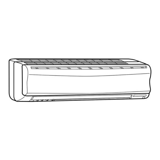
SPLIT-TYPE AIR CONDITIONERS
INDOOR UNIT
SERVICE MANUAL
Models
MSZ-A18YV -
MSZ-A24YV -
MSZ-A26YV -
MSZ-A18YV -
MSZ-A24YV -
MSZ-A26YV -
NOTE:
This service manual describes technical data of the indoor unit.
•Refer to the service manual OB346 when MSZ-A18YV -
is connected with MUZ-A18YV -
•Refer to the service manual OB319 when MSZ-A18YV -
is connected with MXZ-A26WV -
Revision A :
• Parts numbers of indoor fan motor and motor band have
• Another type of the electronic control P.C.board (TYPE 2)
• Some descriptions have been modified.
Please void OB345.
E1
E1
E1
CONTENTS
1. PART NAMES AND FUNCTIONS······················2
2. SPECIFICATION·················································4
3. NOISE CRITERIA CURVES ·······························5
4. OUTLINES AND DIMENSIONS ·························6
5. WIRING DIAGRAM ············································7
6. REFRIGERANT SYSTEM DIAGRAM ················8
7. SERVICE FUNCTIONS ······································9
8. TROUBLESHOOTING······································11
9. DISASSEMBLY INSTRUCTIONS ····················20
E1
10. PARTS LIST······················································22
E1
11. OPTIONAL PARTS·······················BACK COVER
E1
, MSZ-A24YV -
E1
, MUZ-A24YV -
or MUZ-A26YV -
E1
E1
, MSZ-A24YV -
E1
or MXZ-A32WV -
as multi system units.
E1
E1
been changed.
has been added to the original one (TYPE 1).
They are both compatible with MSZ-A18/24/26YV-
REVISED EDITION-A
or MSZ-A26YV -
E1
.
E1
or MSZ-A26YV -
E1
.
E
No. OB345
E1
E1
Advertisement
Table of Contents

Subscribe to Our Youtube Channel
Related Manuals for Mitsubishi Electric MSZ-A18YV-E1


Summary of Contents for Mitsubishi Electric MSZ-A18YV-E1
-
Page 1: Table Of Contents
Revision A : • Parts numbers of indoor fan motor and motor band have been changed. • Another type of the electronic control P.C.board (TYPE 2) SPLIT-TYPE AIR CONDITIONERS has been added to the original one (TYPE 1). They are both compatible with MSZ-A18/24/26YV- •... -
Page 2: Part Names And Functions
Use the specified refrigerant only Never use any refrigerant other than that specified. Doing so may cause a burst, an explosion, or fire when the unit is being used, serviced, or disposed of. Correct refrigerant is specified in the manuals and on the spec labels provided with our products. We will not be held responsible for mechanical failure, system malfunction, unit breakdown or accidents caused by failure to follow the instructions. - Page 3 REMOTE CONTROLLER MSZ-A18YV - MSZ-A24YV - MSZ-A26YV - Signal transmitting section Operation display section OPERATE /STOP (ON /OFF)button ON/OFF WARM COOL TEMPERATURE buttons Indication of remote controller model is on back. Open the front lid. CLOCK ON/OFF WARM COOL VANE button FAN SPEED CONTROL button STOP (Horizontal vane button)
-
Page 4: Specification
SPECIFICATION •Refer to the service manual OB346 when MSZ-A18YV - , MSZ-A24YV - or MSZ-A26YV - is connected with MUZ-A18YV - , MUZ-A24YV - or MUZ-A26YV - •Refer to the service manual OB319 when MSZ-A18YV - , MSZ-A24YV - or MSZ-A26YV - is connected with MXZ-A26WV - or MXZ-A32WV -... -
Page 5: Noise Criteria Curves
Specifications and rating conditions of main electric parts INDOOR UNIT Model MSZ-A26YV - MSZ-A18YV - MSZ-A24YV - Item (C11) Indoor fan capacitor 2.5+ 440V (F11) Fuse 250V 3.15A (MV1/ MV2) Vane motor MP20/MP20 (NR11) Varistor TNR10V511K410 (SR141) Solid state relay S201DH1N (TB) Terminal block... -
Page 6: Outlines And Dimensions
OUTLINES AND DIMENSIONS MSZ-A18YV - Unit: mm MSZ-A24YV - MSZ-A26YV - INDOOR UNIT Installation plate Indoor unit 1068 414.5 414.5 Wall hole [75 Liquid line [ 6.35- 0.5m 1100 Air in Installation plate Gas line [ 12-0.43m Insulation [ 50 O.D [ 32 I.D for MSZ-A18/A24YV Liquid line [ 9.52- 0.5m... -
Page 7: Wiring Diagram
WIRING DIAGRAM MSZ-A18YV - MODEL WIRING DIAGRAM INDOOR UNIT RT13 TO OUTDOOR HIC1 UNIT RT12 CONNECTING CN201 CN112 NR11 TRANS SR141 TAB12 POWER SUPPLY CN211 CORD RT11 ELECTRONIC CONTROL P.C. BOARD ~/N 230V 50Hz DISPLAY RECEIVER CIRCUIT P.C. BOARD P.C. BOARD BREAKER REMOTE CONTROLLER... -
Page 8: Refrigerant System Diagram
REFRIGERANT SYSTEM DIAGRAM MSZ-A18YV - MSZ-A24YV - Unit:mm INDOOR UNIT INDOOR UNIT Refrigerant pipe [15.88 Refrigerant pipe [12.7 (with heat insulator) (with heat insulator) Indoor coil Indoor coil thermistor Indoor Indoor thermistor RT12(main) heat RT12(main) heat exchanger exchanger Distributor Distributor Flared connection Flared connection Indoor coil... -
Page 9: Service Functions
SERVICE FUNCTIONS MSZ-A18YV - MSZ-A24YV - MSZ-A26YV - 7-1. TIMER SHORT MODE For service, set time can be shortened by short circuit of JPG and JPS on the electronic control P.C. board. The time will be shortened as follows. Set time : 1 minute 1-second Set time : 3 minute 3-second (It takes 3 minutes for the compressor to start operation. - Page 10 How to disable “AUTO RESTART FUNCTION” Turn off the main power for the unit. Pull out the electronic control P.C. board, the receiver P.C. board and the display P.C.board. (Refer to page 20.) Solder jumper wire to the RESISTOR JR07 on the indoor electronic control P.C. board. (Refer to page 18. and 19) Operation If the main power has been cut, the operation settings remain.
-
Page 11: Troubleshooting
TROUBLESHOOTING MSZ-A18YV - MSZ-A24YV - MSZ-A26YV - 8-1. Cautions on troubleshooting 1. Before troubleshooting, check the following: (1) Check the power supply voltage. (2) Check the indoor/outdoor connecting wire for mis-wiring. 2. Take care the following during servicing. (1) Before servicing the air conditioner, be sure to first turn off the remote controller to stop the main unit, and then after confirming the horizontal vane is closed, turn off the breaker and / or disconnect the power plug. - Page 12 8-2. Instruction of troubleshooting Start Indoor unit Indoor unit operates. Indoor unit OPERATION INDICATOR operates. Outdoor unit does not does not receive lamp on the indoor unit is Outdoor unit operate normally. the signal from flashing on and off. does not remote controller.
- Page 13 1. Troubleshooting check table • The following indication applies regardless of shape of the indicator. · Flashing of the OPERATION INDICATOR lamp (the left-hand side lamp) indicates Operation Indicator Lighted possible abnormalities. · The OPERATION INDICATOR lamp (the left-hand side lamp) is lighting during Not lighted normal operation.
- Page 14 2. Trouble criterion of main parts MSZ-A18YV - MSZ-A24YV - MSZ-A26YV - Part name Figure Check method and criterion Measure the resistance with a tester. Room temperature (Part temperature 10˚C ~ 30˚C) thermistor(RT11) Normal Abnormal Indoor coil thermistor Open or short-circuit 8 k"...
- Page 15 When OPERATION INDICATOR lamp flashes 3-time. Indoor fan motor does not operate. Check of indoor fan motor Turn OFF the power supply. Check connector CN211 visually. Is soldered point of the connector Are lead wires connected? Resolder it. correctly soldered? Reconnect the lead wires.
- Page 16 The unit does not operate with the remote controller. Also, the OPERATION INDICATOR lamp does not light up by pressing the EMERGENCY OPERATION switch. Check of indoor electronic control P.C. board Check the both “parts side” and “pattern Varistor (NR11) side”...
- Page 17 When OPERATION INDICATOR lamp flashes ON and OFF in every 0.5-second. Outdoor unit does not operate. How to check mis-wiring and serial signal error (when outdoor unit does not work) Start • Turn ON the power supply (Indoor/ outdoor unit). •...
- Page 18 TEST POINT DIAGRAM AND VOLTAGE MSZ-A18YV - MSZ-A24YV - MSZ-A26YV - Indoor electronic control P.C. board w There are 2 types of electronic control P.C. boards (TYPE1/TYPE2). TYPE 1 They are both compatible with MSZ-A18/24/26YV. Fan motor power supply (CN211) Power supply input 230 VAC 5 VDC...
- Page 19 TEST POINT DIAGRAM AND VOLTAGE MSZ-A18YV - MSZ-A24YV - MSZ-A26YV - Indoor electronic control P.C. board TYPE 2 Fan motor power supply (CN211) Power supply input 230 VAC Fuse (F11) 250 VAC 3.15A 5 VDC R132 Room temperature thermistor (RT11) Indoor coil thermistor (RT12 (main)) Indoor coil thermistor...
-
Page 20: Disassembly Instructions
DISASSEMBLY INSTRUCTIONS <"Terminal with lock mechanism" Detaching points> In case of terminal with lock mechanism, detach the terminal as shown below. There are two types ( Refer to (1) and (2)) of the terminal with lock mechanism. The terminal with no lock mechanism can be removed by pulling it out. Check the shape of the terminal and work. - Page 21 OPERATING PROCEDURE PHOTOS 3. Removing the electrical box Photo 3 Screws of the earth wire (1) Remove the front panel. (Refer to 1.) (2) Remove the electrical cover. (Refer to 2.) (3) Disconnect the connector of the indoor coil thermistor. (4) Disconnect the motor connector (CN211 and CN121) and the vane motor connector (CN151) on the electronic control P.C.
-
Page 22: Parts List
PARTS LIST (non-RoHS compliant) MSZ-A18YV - (WH) MSZ-A24YV - (WH) MSZ-A26YV - (WH) 10-1. INDOOR UNIT STRUCTURAL PARTS 10-2. INDOOR UNIT HEAT EXCHANGER CATCH Optional parts (See 11.) SCREW 10-1. INDOOR UNIT STRUCTURAL PARTS Part number that is circled is not shown in the illustration. Q'ty/unit Symbol MSZ-A18... - Page 23 PARTS LIST (non-RoHS compliant) MSZ-A18YV - (WH) MSZ-A24YV - (WH) MSZ-A26YV - (WH) 10-4. ACCESSORY AND 10-3. INDOOR UNIT FUNCTIONAL PARTS AND REMOTE CONTROLLER ELECTRICAL PARTS SLEEVE BEARING ROOM TEMPERATURE THERMISTOR 16 17 VARISTOR FUSE 10-3. INDOOR UNIT FUNCTIONAL PARTS AND ELECTRICAL PARTS Part numbers that are circled are not shown in the illustration.
-
Page 24: Optional Parts
MSZ-A26YV - Air cleanig filter (White bellows type) HEAD OFFICE: MITSUBISHI BLDG.,2-7-3, MARUNOUCHI, CHIYODA-KU, TOKYO100-8310, JAPAN C Copyright 2004 MITSUBISHI ELECTRIC CORPORATION Distributed in Mar. 2012. No.OB345 REVISED EDITION-A New publication, effective Mar. 2012 Distributed in Apr. 2004. No.OB345 6 Made in Japan Specifications are subject to change without notice.
Need help?
Do you have a question about the MSZ-A18YV-E1 and is the answer not in the manual?
Questions and answers