Table of Contents

Related Manuals for TQ Environmental TQ8000


Summary of Contents for TQ Environmental TQ8000
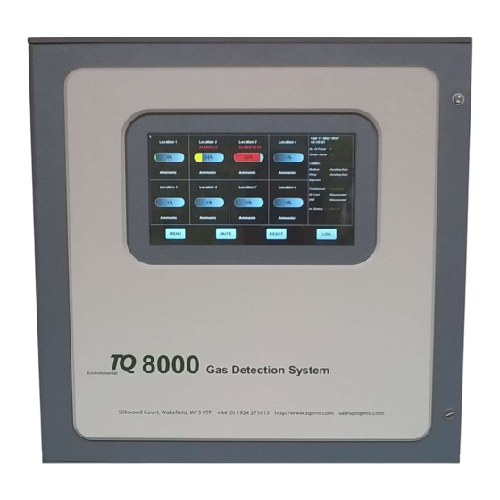
- Page 1 TQ8000 Touch 48 Channel Monitoring System OPERATING MANUAL TQ Environmental Limited Tel: +44 (0) 1924 271013 Silkwood Court Fax: +44 (0) 1924 264420 Wakefield WF5 9TP Email: sales@tqenv.com United Kingdom Web: www.tqenv.com...
-
Page 2: Table Of Contents
TQ Environmental Limited Table of Contents PROPRIETARY ..............................4 COPYRIGHT ................................ 4 WARNINGS, CAUTIONS AND NOTES ....................... 4 SAFETY WARNINGS ............................5 1.0 Introduction ............................... 6 Specification ............................. 7 2.0 Description ................................. 8 2.1 Adaptor PCB ..............................9 2.2 Control Board ..............................9 2.3 Display ................................ - Page 3 TQ Environmental Limited 7.4 Pellistor Sensor Set Up ..........................38 7.4.1 Pellistor Bridge Voltage ......................... 39 7.4.2 Bridge Balance Voltage ......................... 39 8.0 Fault Finding ..............................40 8.1 Power Supply ............................... 40 8.2 Sensor ................................40 Page 3 of 43...
-
Page 4: Proprietary
TQ Environmental Limited does not assume any liability arising out of the application or any use of any product or circuit described herein; neither does it convey license under its patent rights or the rights of others. -
Page 5: Safety Warnings
THE OPERATION DESCRIBED IN THIS DOCUMENT IS THE INTENDED USE OF THE TQ8000 Touch. TQ ENVIRONMENTAL LIMITED CANNOT BE HELD RESPONSIBLE IF THE TQ8000 Touch IS USED FOR ANY PURPOSE OTHER THAN THAT STATED. ANY OTHER USE OF THE TQ8000 Touch WILL INVALIDATE ANY CERTIFICATES ISSUED. -
Page 6: Introduction
‘Mute’ functions. An internal password protected Menu allows the user to calibrate or re-configure each input. The TQ8000 Touch in its native form provides a neat, “flush to wall” installation by using the three internal mounting points. TYPICAL INSTALLATION... -
Page 7: Specification
TQ Environmental Limited Specification Std 8 x 2/3 wire 4-20mA source, or 3 wire Pellistor type. Inputs: Expandable up to 48 inputs Outputs: 16 SPCO relays, rating: 24 Vdc/280V ac @ 12A resistive local in Panel 32 SPCO relays, rating: 24 Vdc/280V ac @ 12A resistive local or external to panel 1 x 4-20mA source per input. -
Page 8: Description
TQ Environmental Limited 2.0 Description The TQ8000 Touch is based around a Control Board communicating with three other electronic units to monitor each of the 8 channels and provide display and alarm functions. These units are: - Adaptor PCB ... -
Page 9: Adaptor Pcb
This PCB has 16 relay SPCO outputs, and is fitted under the Adaptor Board. All of the relays are configurable to operate for any level of alarm on any of the eight channels. The TQ8000 Touch provides a ‘Latched’ or ‘Non-Latched’ and ‘normally On’ or ‘Normally Off’ configuration for individual relays. -
Page 10: Remote Relay Board (If Fitted)
TQ Environmental Limited 2.5 Remote Relay Board (if fitted) This PCB is available with 16 relay SPCO outputs. It may be fitted within the TQ8000 Touch enclosure or within an enclosure separate from the rest of the TQ8000 Touch unit. - Page 11 TQ Environmental Limited Figure 3 Page 11 of 43 17654PM Issue: 3 December 2022...
-
Page 12: Operation
When the TQ8000 Touch is first powered on the system starts loading EEPROM configuration data and then enters ‘Start-up’ mode. It will remain in this mode for 120 seconds to enable the sensors to stabilise. During the start-up mode the TQ8000 Touch will not generate any alarms or activate any relays. -
Page 13: Gas/Input Alarms
‘falling’ alarms and can be configured in any combination for each channels. In a low alarm condition (alarm level 1), the TQ8000 Touch display will show the alarm status on the respective channel that is in alarm as well as an alarm condition in the System Status field on the right-hand side of the display. - Page 14 TQ Environmental Limited Figure 6 In a High alarm condition (alarm level 2), the TQ8000 Touch display will show the alarm status on the respective channel that is in alarm as well as an alarm condition in the System Status field on the right-hand side of the display. The concentration value is shown inside the concentration box and the colour will change to Orange to indicate a HI Alarm.
- Page 15 TQ Environmental Limited Figure 7 In a High High alarm condition (alarm level 3), the TQ8000 Touch display will show the alarm status on the respective channel that is in alarm as well as an alarm condition in the System Status field on the right-hand side of the display. The concentration value is shown inside the concentration box and the colour will change to Red to indicate a HIHI Alarm.
-
Page 16: Fault
TQ Environmental Limited Fault Any sensor fault will cause the TQ8000 Touch to indicate a ‘FAULT’ above the respective sensor as well as a Fault condition in the System Status field on the right- hand side of the display. The internal sounder will operate and any relays will activate/de-activate that have been pre-configured for that fault condition. -
Page 17: Acknowledge Alarms
Reset Alarms When the respective channel has returned to its’ normal operation from an ‘Alarm’ or ‘Fault’ condition, the ‘RESET’ button will return the TQ8000 Touch Display and relays to normal and the internal sounder will be silenced. Page 17 of 43... -
Page 18: Sensor View
TQ Environmental Limited Sensor View Individual sensor information may be obtained by pressing on the particular sensors Location Name. A graph will be available indicating the real-time data for that sensor. The concentration is shown on a dashboard with the sensor output (in mA) and the digital ADC value for investigation purposes. -
Page 19: Data Log View
TQ Environmental Limited 3.10 Data Log View Pressing the ‘LOG’ button will bring up the Data Log View if an SD Card is present. Figure 12 Pressing the ‘START’ button will go to the beginning of the Data Log file, or pressing the ‘END’... -
Page 20: System Menus
System the user may press the ‘C’ button to cancel password entry and return to the Main System View window. While accessing the Menu System, if the user fails to interact with the TQ8000 Touch the system will return to the Main System View window after 20 minutes and resume normal operation. -
Page 21: System Configuration
TQ Environmental Limited 4.2 System Configuration Figure 14 This Menu window enables the setting of the main system configuration. These include:- Setting the Number of Channels Setting the Modbus Station Number Setting the Sensor Fault Level in mA ... -
Page 22: Channel Configuration
TQ Environmental Limited 4.2 Channel Configuration This Menu screen will allow the Location Names, Gas Names and Gas Units to be changed by pressing the tabs at the top of the screen. Figure 15 If using a system with more than eight channels/sensors, the user may swipe the bottom of the screen left or right to select other pages of channels/sensors. - Page 23 TQ Environmental Limited Figure 16 To select text in the Edit Box the user may long-press the desired text to highlight it. When the text field is highlighted the user will be able to Copy the text by pressing the ‘Copy’...
-
Page 24: Alarm Configuration
TQ Environmental Limited 4.3 Alarm Configuration This Menu allows the alarms to be configured for each channel/sensor. Figure 17 The required channel/sensor may be selected using the Up/Down arrow buttons. With the correct sensor/channel selected the user may set the Sensor Range by pressing the Sensor Range Edit Box. -
Page 25: Relays Configuration
TQ Environmental Limited Similarly the alarm set points may be edited for Alarm 1, Alarm 2 and Alarm3. Long pressing the edit boxes will highlight the value to enable the Copy, Paste, Paste All functions. Alarms may be set to be Rising(+) or Falling(-) by pressing (toggling) the appropriate buttons for Alarm 1, Alarm 2 and Alarm 3. -
Page 26: Calibration
The user may save the settings by pressing the ‘SAVE’ button. 4.5 Calibration The Calibrate Sensor screen is used to calibrate the TQ8000 Touch system’s sensors. The required sensor to calibrate is selected using the Sensor Left/Right arrow buttons. Figure 20 The top right-hand side of the display shows current Location Name, Sensor Range and Digital ADC Calibration Values for the selected sensor. -
Page 27: Span Setup
4.5.2 Span Setup As with the ‘Zero’ set-up, to cater for the numerous sensor types that can be used with the TQ8000 Touch, ‘Span’ setup will be for a value at the higher end of the sensor range. Ensure that the sensor under calibration is exposed to its span conditions, and allow the concentration value displayed to stabilise. - Page 28 The user selects the Comms ports by pressing the tabs at the top of the screen. The values can be changed by moving the wheels to the required positions. The COM ports on the TQ8000 Touch are assigned as follows: ...
-
Page 29: Relay Test
TQ Environmental Limited 4.8 Relay Test The Local Relays and Remote Relay (if fitted) may be individually activated using this menu screen. Figure 23 The Relay Board can be selected by pressing the Left/Right arrow buttons. The Green LED above the relay number indicates that the relay is currently activated while a Red LED indicates that the relay is currently de-activated. -
Page 30: Default Data
TQ Environmental Limited 4.9 Default Data This is used to download the default data for the complete TQ8000 Touch system. A warning dialog window is shown requiring the user to confirm the downloading of the system data. Figure 24 Page 30 of 43... -
Page 31: Modbus Communications
TQ Environmental Limited 5.0 Modbus Communications This section specifies the MODBUS output of the TQ8000 Touch. It details the protocol used and information that is made available over the protocol. 5.1 Communications In MODBUS communications there is a Master device and a number of Slave devices. - Page 32 TQ Environmental Limited 10017 10065 10113 10161 10209 10257 10305 10018 10066 10114 10162 10210 10258 10306 10019 10067 10115 10163 10211 10259 10307 10020 10068 10116 10164 10212 10260 10308 10021 10069 10117 10165 10213 10261 10309 10022 10070...
- Page 33 TQ Environmental Limited 10351 10399 10447 10495 10352 10400 10448 10496 10353 10401 10449 10497 10354 10402 10450 10498 10355 10403 10451 10499 10356 10404 10452 10500 10357 10405 10453 10501 10358 10406 10454 10502 10359 10407 10455 10503 10360...
-
Page 34: Gas Concentrations
TQ Environmental Limited 5.2.2 Gas Concentrations Concentrations are stored in Scientific form and stored in two parts, a reading and a precision part. This should be read RR E PP where RR is the reading and PP is the precision, e.g. 21.2% will be represented as 212E-1 or 212x 10 For the concentrations;... -
Page 35: Installation
6.0 Amps and fitted adjacent to the TQ8000. Connection to the 8 channel TQ8000 will be to the fused terminal block on the power supply tray for 16-48 channel unit it will be t a rail mount fuse isolator on termination rail. -
Page 36: Relay Outputs
TQ Environmental Limited NB The screen of the sensor wiring must not be connected to earth at the sensor, as it must be connected to the ‘Earth’ stud provided within the TQ8000 on the bottom left hand side of the unit. -
Page 37: Commissioning
All wires and screens, including earth wires, are correctly terminated and secure. All sensors are connected to their respective channel inputs as per the TQ8000 Touch configuration sheet. Ensure that all links and Input Modules are fitted correctly in accordance with the requirements of the sensor connected. -
Page 38: Power Up
‘Wheatstone Bridge’ principle and therefore require the ‘bridge voltage’ & ‘bridge balance’ setting up prior to calibration. Upon power up the TQ8000 Touch will wait 120 seconds to allow the attached sensors to complete their self-test. 7.4 Pellistor Sensor Set Up The ‘Input Card’... -
Page 39: Pellistor Bridge Voltage
This normally takes about 1 hour. To ‘balance’ the Pellistor sensor bridge, open the relevant Sensor View page. Adjust the trim-pot VR2 until the reading shows 4.0mA. To clear any channel ‘Fault’ indications, press the TQ8000 Touch front panel ‘Reset’ button. Page 39 of 43... -
Page 40: Fault Finding
F2 +5 Volt dc @2A F3 +24 Volt dc @3A For a power supply fault on the standard TQ8000 Touch 8 way 24 volt dc powered relay outputs, check the ‘Auxiliary’ output fuse ‘F4’. This is rated for the service required and should not be greater than 1.0A. - Page 41 Disconnect the Pellistor sensor, and check the resistance value between ‘+V’ and ‘0V’. This should be a low value from 3 Ohms upwards, depending upon the manufacturer. For Technical assistance on any problem encountered when using the TQ8000 Touch, please do not hesitate to contact: TQ Environmental Ltd Tel: 01924 271013 Fax: 01924 264420 Email: sales@tqenv.com...
- Page 42 TQ Environmental Limited This page is intentionally left blank Page 42 of 43 17654PM Issue: 3 December 2022...
- Page 43 TQ Environmental Limited TQ Environmental Limited Silkwood Court Wakefield West Yorkshire WF5 9TP United Kingdom Page 43 of 43 17654PM Issue: 3 December 2022...
Need help?
Do you have a question about the TQ8000 and is the answer not in the manual?
Questions and answers