Table of Contents
Advertisement
Quick Links
Advertisement
Table of Contents

Subscribe to Our Youtube Channel
Related Manuals for NI PXI-5422


Summary of Contents for NI PXI-5422
- Page 1 PXI-5422...
-
Page 2: Table Of Contents
This document contains instructions for calibrating the NI PXI-5422 arbitrary waveform generator. This calibration procedure is intended for metrology labs. It describes specific programming steps for writing an external calibration procedure for the NI PXI-5422. Refer to for additional information about calibration solutions from ni.com/calibration... -
Page 3: Software Requirements
For the locations of files you may need to calibrate your device, refer to the NI-FGEN Readme, which is available on the NI-FGEN DVD. Calibration functions are C function calls or LabVIEW VIs in NI-FGEN. In this document, the C function call is shown first, followed by the corresponding LabVIEW VI or NI-FGEN LabVIEW property node, in parentheses. -
Page 4: Documentation Requirements
Documentation Requirements Consult the following documents for information about the NI PXI-5422, NI-FGEN, and your application software. All documents are available on , and the Help files install with the ni.com... -
Page 5: Password
Self-Calibration Procedures The NI PXI-5422 can perform self-calibration, which adjusts the gain and offset of the main and direct analog paths. Self-calibration exclusively uses an onboard A/D converter (ADC) to measure the output voltage. You can implement self-calibration on the NI PXI-5422 by... -
Page 6: Max
A pointer to a ViSession. The variable passed by reference through this parameter receives the value that identifies the session created by this function. This value acts as the session handle and is passed as the first parameter to all subsequent NI-FGEN functions. Call... -
Page 7: External Calibration Options
Complete Calibration section describes the recommended calibration procedure. The Optional Calibration section describes alternate procedures that allow you to skip adjustment if the device already meets its calibration test limits or published specifications. 6 | ni.com | NI PXI-5422 Calibration Procedure... -
Page 8: Complete Calibration
Complete Calibration Performing a complete calibration is the recommended way to guarantee that the NI PXI-5422 meets or exceeds its published specifications for a two-year calibration interval. At the end of the complete calibration procedure, you verify that the output error falls within the calibration test limits. - Page 9 Published Specs Temperatures (Adjustment Without Adjusting Optional) Adjust (Cal Dates and Adjust Temperatures Anyway? Updated) Document Verify Post-Adjustment Results Meets Calibration/ Calibration Verification Test Limits? Complete Review Verification/ Adjustment Procedure or Return Device 8 | ni.com | NI PXI-5422 Calibration Procedure...
-
Page 10: External Calibration Requirements
Agilent HP 8560E signal source analyzer sine waves Agilent HP 53131A Frequency accuracy or HP 53132A with to ≤500 ppb timebase option 001, 010, or 012 Rohde & Schwarz (R&S) FSUP NI PXI-5422 Calibration Procedure | © National Instruments | 9... -
Page 11: Test Conditions
External Calibration Procedures The complete external calibration procedure consists of self-calibrating, verifying the performance of the NI PXI-5422, adjusting the calibration constants, and verifying again after the adjustments. In some cases, the complete calibration procedure may not be required. Refer... -
Page 12: Calibration Procedures In C
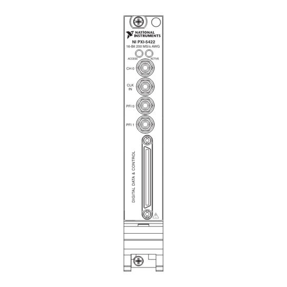
Refer to Table 2 for information about which instrument to use for verifying each specification. Refer to Figure 3 for the names and locations of the NI PXI-5422 front panel connectors. NI PXI-5422 Calibration Procedure | © National Instruments | 11... -
Page 13: Verifying The Oscillator Frequency Accuracy
This test verifies the frequency accuracy of the oscillator on the NI PXI-5422. The verification involves generating a 10 MHz sine wave with the NI PXI-5422 and measuring the sine wave frequency with one of the instruments from Table 2. - Page 14 A pointer to a ViSession. The variable passed by reference through this parameter receives the value that identifies the session created by this function. This value acts as the session handle and is passed as the first parameter to all subsequent NI-FGEN functions.
- Page 15 The session handle returned from niFgen_init 10. Measure the frequency output of the NI PXI-5422. A frequency error of 45 Hz for a 10 MHz signal corresponds to an error of 4.5 ppm. This limit accounts for the initial accuracy and the frequency deviation caused by temperature and aging.
-
Page 16: Verifying The Dc Gain And Offset Accuracy
Verifying the DC Gain and Offset Accuracy This test verifies the DC gain and offset accuracy of the NI PXI-5422 into a high-impedance load by generating a number of DC voltages and offsets, measuring the voltage with a DMM, and comparing the NI PXI-5422 to the error limits. - Page 17 (waveform handle) that identifies the waveform created by this function (positive full-scale handle). 10. Create an array of waveform samples for the negative full-scale DC waveform. This array should contain 500 samples with each sample having the value (representation: -1.0 double). 16 | ni.com | NI PXI-5422 Calibration Procedure...
- Page 18 13. Repeat steps 14 through 24 for each of the 24 iterations listed in Table 4, changing the Gain value for each iteration. You can use Table 4 to record the results of these steps. NI PXI-5422 Calibration Procedure | © National Instruments | 17...
- Page 19 Table 4. Values for Verifying the Gain of the Main Analog Path Ideal Ideal Measured Measured Error Error Positive Negative Positive Negative Positive Negative Calibration Published Full-Scale Full-Scale Full-Scale Full-Scale Full-Scale Full-Scale Test Limit Specification † Iteration Gain (Volts) (Volts) (Volts) (Volts) (Volts)
- Page 20 Table 4. Values for Verifying the Gain of the Main Analog Path (Continued) Ideal Ideal Measured Measured Error Error Positive Negative Positive Negative Positive Negative Calibration Published Full-Scale Full-Scale Full-Scale Full-Scale Full-Scale Full-Scale Test Limit Specification † Iteration Gain (Volts) (Volts) (Volts) (Volts)
- Page 21 The session handle returned from niFgen_init 17. Measure the DC voltage output of the NI PXI-5422. Record this value in the Measured Positive Full-Scale value column of Table 4. 18. Subtract the Ideal Positive Full-Scale value from the Measured Positive Full-Scale value and record the result under Error Positive Full-Scale.
- Page 22 Calibration Test Limit or the Published Specification, perform an external adjustment. Verifying the Main Analog Path Offset To verify the offset of the NI PXI-5422 main analog path, complete the following steps: Create an array of waveform samples for the mid-scale DC waveform (0 VDC). This array...
- Page 23 Table 5. Values for Verifying the Offset of the Main Analog Path Ideal Ideal Measured Measured Error Error Positive Negative Positive Negative Positive Negative Calibration Published Offset Offset Offset Offset Offset Offset Test Limit Specification † Iteration Gain (Volts) (Volts) (Volts) (Volts) (Volts)
- Page 24 Table 5. Values for Verifying the Offset of the Main Analog Path (Continued) Ideal Ideal Measured Measured Error Error Positive Negative Positive Negative Positive Negative Calibration Published Offset Offset Offset Offset Offset Offset Test Limit Specification † Iteration Gain (Volts) (Volts) (Volts) (Volts)
- Page 25 The session handle returned from niFgen_init 13. Measure the negative DC voltage out of the NI PXI-5422. Record negative DC voltage out measurement in the Measured Negative Offset column of Table 5. 14. Subtract the Ideal Negative Offset from the Measured Negative Offset and record the result under Error Negative Offset.
- Page 26 Calibration Test Limit or the Published Specification, perform an external adjustment. Verifying the Gain of the Direct Analog Path To verify the gain of the NI PXI-5422 direct analog path, complete the following steps: Note The offset is not adjustable for the direct analog path.
- Page 27 Table 6. Values for Verifying the Gain of the Direct Analog Path Ideal Ideal Measured Measured Error Error Positive Negative Positive Negative Offset Positive Negative Calibration Published Full-Scale Full-Scale Full-Scale Full-Scale Offset Limit Full-Scale Full-Scale Test Limit Specification Iteration Gain (Volts) †...
- Page 28 • vi: The session handle returned from niFgen_init 11. Measure the negative DC voltage out of the NI PXI-5422. Record the negative DC voltage out measurement in the Measured Negative Full-Scale Value column of Table 6. 12. Call (niFgen Abort Generation VI) to abort the waveform...
-
Page 29: Verifying The Ac Voltage Amplitude Absolute Accuracy
Verifying the AC Voltage Amplitude Absolute Accuracy This test verifies the AC voltage amplitude absolute accuracy of the NI 5422 using a DMM. To verify the AC accuracy of the NI 5422, complete the following steps: Connect the NI 5422 CH 0 front panel connector to the DMM. Connect positive terminal to the center pin of the NI 5422 SMB connector, and connect the negative terminal to the shield. - Page 30 Digits: 6.5 Note These values assume you are using an NI 4070 DMM. For other DMMs, use the range closest to the values listed in step 10. The input impedance should be equal to or greater than the values indicated in Table 2,...
- Page 31 (NI-FGEN Gain property) to set the gain using niFgen_SetAttributeViReal64 the following parameters: • vi: The session handle returned from niFgen_init • channelName: "0" • attributeID: NIFGEN_ATTR_ARB_GAIN • value: The Gain value listed in Table 7 for the current iteration. 30 | ni.com | NI PXI-5422 Calibration Procedure...
-
Page 32: Verifying Frequency Response (Flatness)
The session handle returned from niFgen_init Verifying Frequency Response (Flatness) This test verifies the frequency response (flatness) of the NI 5422 using a power meter. The flatness verification has two subprocedures that verify the following: • Main analog path flatness: low-gain amplifier and high-gain amplifier •... - Page 33 (niFgen property node: Output niFgen_SetAttributeViBoolean Attributes»Analog Filter Enabled) to set the analog filter state using the following parameters: • vi: The session handle returned from niFgen_init • channelName: "0" • attributeID: NIFGEN_ATTR_ANALOG_FILTER_ENABLED • value: VI_TRUE 32 | ni.com | NI PXI-5422 Calibration Procedure...
- Page 34 200000000 13. Repeat steps 14 through 23 for each iteration in Table 8, changing the Number of Samples Number of Cycles for each iteration. Table 8. NI 5422 Setup for Main Analog Path Flatness Verification Published Specification Number Number Low-Gain...
- Page 35 (niFgen Close VI) to close the instrument driver session, destroy the niFgen_close instrument driver session and all of its properties, and release any memory resources that NI-FGEN uses. Use the following parameter: • vi: The session handle returned from niFgen_init 34 | ni.com | NI PXI-5422 Calibration Procedure...
- Page 36 Verifying the Direct Analog Path Flatness To verify the direct analog path flatness of the NI 5422, complete the following steps: Connect the NI 5422 CH 0 front panel connector to the power meter using the required adapter. Call (niFgen Initialize VI) using the following parameters: niFgen_init •...
- Page 37 13. Repeat steps 14 through 22 for each iteration in Table 9, changing the Number of Samples Number of Cycles for each iteration. Table 9. NI 5422 Setup for Direct Analog Path Flatness Verification Number of Number of Published Iteration...
- Page 38 Table 9. NI 5422 Setup for Direct Analog Path Flatness Verification (Continued) Number of Number of Published Iteration Frequency Samples Cycles Specification 60 MHz 2,000 -3.4 dB to +0.4 dB 70 MHz 2,000 -3.4 dB to +0.4 dB 80 MHz 2,000 -3.4 dB to +0.4 dB...
-
Page 39: Adjusting The Ni Pxi-5422
If the NI PXI-5422 was not within the calibration test limits for each verification procedure, perform the adjustment procedure to improve the accuracy of the NI PXI-5422. Refer... - Page 40 ADC gain and offset so that self-calibration results in an accurately calibrated device. You cannot perform an external calibration using a standard NI-FGEN session. You must create an external calibration session using (niFgen Init Ext Cal VI). An...
-
Page 41: Initializing The External Calibration Session
Direct analog path gain In each of these sub-procedures, you put the device in several configurations and take several output measurements. You then pass these measurements to NI-FGEN, which determines the calibration constants for the device. Initializing Analog Output Calibration... - Page 42 (NI-FGEN Output niFgen_SetAttributeViReal64 Impedance property) using the following parameters: • vi: The session handle returned from niFgen_InitExtCal • channelName: "0" • attributeID: NIFGEN_ATTR_OUTPUT_IMPEDANCE • value: NI PXI-5422 Calibration Procedure | © National Instruments | 41...
- Page 43 Enable, Pre-amplifier Attenuation, and Current Configuration values for each iteration. Table 10. Attributes and Values for Main Analog Path Pre-amplifier Offset Analog Filter Pre-amplifier Iteration Enable Attenuation Current Configuration VI_FALSE NIFGEN_VAL_CAL_CONFIG_MAIN_PATH_FILTER_OFF_0DB VI_FALSE NIFGEN_VAL_CAL_CONFIG_MAIN_PATH_FILTER_OFF_3DB VI_FALSE NIFGEN_VAL_CAL_CONFIG_MAIN_PATH_FILTER_OFF_6DB 42 | ni.com | NI PXI-5422 Calibration Procedure...
- Page 44 NIFGEN_ATTR_PRE_AMPLIFIER_ATTENUATION • value: The Pre-amplifier Attenuation value for the current iteration from Table 10. Call the following functions and take voltage measurements at the NI PXI-5422 CH 0 front panel connector into a high-impedance load: Call to set the gain DAC value (NI-FGEN Gain...
- Page 45 The Current Configuration value for the current iteration from Table 10. • gainDACValues: An array containing two elements—the two values ( 2000 1000 that you set as the gain DAC in the order that you measured them. 44 | ni.com | NI PXI-5422 Calibration Procedure...
- Page 46 Table 11. Attributes and Values for Main Analog Path Pre-amplifier Gain Analog Filter Pre-amplifier Iteration Enable Attenuation Current Configuration VI_FALSE NIFGEN_VAL_CAL_CONFIG_MAIN_PATH_FILTER_OFF_0DB VI_FALSE NIFGEN_VAL_CAL_CONFIG_MAIN_PATH_FILTER_OFF_3DB VI_FALSE NIFGEN_VAL_CAL_CONFIG_MAIN_PATH_FILTER_OFF_6DB VI_FALSE NIFGEN_VAL_CAL_CONFIG_MAIN_PATH_FILTER_OFF_9DB VI_FALSE NIFGEN_VAL_CAL_CONFIG_MAIN_PATH_FILTER_OFF_12DB VI_TRUE NIFGEN_VAL_CAL_CONFIG_MAIN_PATH_FILTER_ON_0DB NI PXI-5422 Calibration Procedure | © National Instruments | 45...
- Page 47 NIFGEN_ATTR_PRE_AMPLIFIER_ATTENUATION • value: The Pre-amplifier Attenuation value for the current iteration from Table 11. Call the following functions to take voltage measurements at the NI PXI-5422 CH 0 front panel connector into a high-impedance load: Call to set the gain DAC value (NI-FGEN Gain...
- Page 48 (niFgen Write Binary 16 Analog niFgen_WriteBinary16AnalogStaticValue Static Value VI) to set the main DAC value using the following parameters: • vi: The session handle returned from niFgen_InitExtCal • channelName: "0" • value: NI PXI-5422 Calibration Procedure | © National Instruments | 47...
- Page 49 The session handle returned from niFgen_InitExtCal • channelName: "0" • attributeID: NIFGEN_ATTR_PRE_AMPLIFIER_ATTENUATION • value: Call to set the gain DAC value (NI-FGEN Gain DAC niFgen_SetAttributeViInt32 Value property) using the following parameters: • vi: The session handle returned from niFgen_InitExtCal • channelName: "0" • attributeID: NIFGEN_ATTR_GAIN_DAC_VALUE •...
- Page 50 NIFGEN_ATTR_POST_AMPLIFIER_ATTENUATION • value: The Post-Amplifier Attenuation value for the current iteration from Table 12. Take the following voltage measurements at the NI PXI-5422 CH 0 front panel connector into a high-impedance load: Call to set the offset DAC value (NI-FGEN...
- Page 51 The session handle returned from niFgen_InitExtCal • channelName: "0" • value: Call to set the gain DAC value (NI-FGEN Gain DAC niFgen_SetAttributeViInt32 Value property) using the following parameters: • vi: The session handle returned from niFgen_InitExtCal • channelName: "0"...
- Page 52 • vi: The session handle returned from niFgen_InitExtCal 11. Take the following voltage measurements at the NI PXI-5422 CH 0 front panel connector into a high-impedance load: Call (niFgen Write Binary 16 niFgen_WriteBinary16AnalogStaticValue Analog Static Value VI) to set the main DAC value using the following parameters: •...
- Page 53 DAC value (NI-FGEN Gain niFgen_SetAttributeViInt32 DAC Value property) using the following parameters: • vi: The session handle returned from niFgen_InitExtCal • channelName: "0" • attributeID: NIFGEN_ATTR_GAIN_DAC_VALUE • value: 1500 52 | ni.com | NI PXI-5422 Calibration Procedure...
-
Page 54: Adjusting The Oscillator Frequency
Adjusting the oscillator frequency involves generating a sine wave at a desired frequency and then iteratively measuring the frequency, passing the measured value to NI-FGEN so that the oscillator can be adjusted, and then remeasuring the resulting frequency. This process is repeated until the difference between the desired and measured frequency falls within the desired tolerance, which is 4.5 ppm. - Page 55 "0" • attributeID: NIFGEN_ATTR_OUTPUT_IMPEDANCE • value: Call to enable the analog output (NI-FGEN Output niFgen_SetAttributeViBoolean Enabled property) using the following parameters: • vi: The session handle returned from niFgen_InitExtCal • channelName: "0" 54 | ni.com | NI PXI-5422 Calibration Procedure...
- Page 56 The session handle returned from niFgen_InitExtCal • desiredFrequencyInHz: The desired frequency ( ) of the generated 10000000 sinusoid in Hz. • measuredFrequencyInHz: The of the generated measured frequency sinusoid in Hz. NI PXI-5422 Calibration Procedure | © National Instruments | 55...
-
Page 57: Adjusting The Calibration Adc
Adjusting the Calibration ADC The NI PXI-5422 has an onboard calibration ADC that is used during self-calibration. Adjusting the calibration ADC involves characterizing the gain and offset associated with this ADC so that performing self-calibration results in an accurately calibrated device. - Page 58 13. Call to set the calibration ADC input (NI-FGEN Cal niFgen_SetAttributeViInt32 ADC Input property) using the following parameters: • vi: The session handle returned from niFgen_InitExtCal • channelName: (empty string) "" NI PXI-5422 Calibration Procedure | © National Instruments | 57...
- Page 59 The session handle returned from niFgen_InitExtCal 21. Wait 500 ms for the output to settle. 22. Use the DMM to measure the NI PXI-5422 voltage output directly into the DMM into a high-impedance load. This measurement is , which is used external measurement 0 in step 32.
- Page 60 The session handle returned from niFgen_InitExtCal 30. Wait 500 ms for the output to settle. 31. Use the DMM to measure the NI PXI-5422 voltage output directly into the DMM (into a high-impedance load). This measurement be , which is used external measurement 1 in step 32.
-
Page 61: Closing The External Adjustment Session
If any errors occurred during the external adjustment procedure or if you want to abort the operation, use . This function discards NIFGEN_VAL_EXT_CAL_ABORT the new calibration constants and does not change any of the calibration data stored in the onboard EEPROM. 60 | ni.com | NI PXI-5422 Calibration Procedure... -
Page 62: Calibration Utilities
Calibration Utilities NI-FGEN supports several calibration utilities that allow you to retrieve information about adjustments performed on the NI PXI-5422, restore an external calibration, change the external calibration password, and store small amounts of information in the onboard EEPROM. You can retrieve some data using MAX or the FGEN SFP;... -
Page 63: Where To Go For Support
National Instruments Patents Notice at ni.com/patents. You can find information about end-user license agreements (EULAs) and third-party legal notices in the readme file for your NI product. Refer to the Export Compliance Information at ni.com/legal/export-compliance for the National Instruments global trade compliance policy and how to obtain relevant HTS codes,...
Need help?
Do you have a question about the PXI-5422 and is the answer not in the manual?
Questions and answers