Table of Contents
Advertisement
Quick Links
Advertisement
Table of Contents

Subscribe to Our Youtube Channel
Related Manuals for SKF 85831

Summary of Contents for SKF 85831
- Page 1 Assembly guide Electric vent assembly Models 85831, 85832, 85833, 85834, 85835, 85836, for use with FlowMaster and FlowMaster II electric pumps on drum cover 85474, 85757 (120 lb.) and 85475, 85758 (400 lb.) drum Date of issue June 2021 Form number...
-
Page 2: Table Of Contents
Contents Signal words for safety ... . . Safety ......Owner/operator responsibility . -
Page 3: Signal Words For Safety
Explanation of signal Safety WARNING words for safety Assembly must only be installed, main- Read and carefully observe these installation tained, and repaired by persons familiar instructions before installing/operating/ with these operating instructions. troubleshooting the assembly. The assembly Do not attempt to install, use, or trou- must be installed, maintained and repaired bleshoot prior to fully understanding all NOTE... -
Page 4: Owner/Operator Responsibility
Power source Drum size followed while installing electric vent valve It is the responsibility of the owner/operator assembly on a 120 lb. (54 kg) or 400 lb. 85831 230 V AC 120 lbs. (54 kg) to properly use and maintain equipment. -
Page 5: Installation
Installation 5 Attach safety unloader (6) to external run tee (7). 6 Attach external run tee (7) to pump Electric vent valve outlet (8). 1 Fasten pump to drum cover (26). 7 Insert hose assembly (4) into vent 2 Assemble hex nut (2) and gasket (3) to fitting (5). -
Page 6: Solenoid Vent Valve
Solenoid vent valve Fig. 2 1 Thread elbow (11) onto reducer nipple (18) and hand-tighten († Fig. 2). 2 Insert reducer nipple (18) into solenoid vent valve (16) and hand-tighten. 3 Thread adapter (17) into solenoid vent valve (16). 4 Insert adapter (15) into solenoid vent valve (16). - Page 7 Drum cover mounting - 400 lb. Fig. 4 (181 kg) drum 1 Place lock washers (19) on hex head screws (20) († Fig. 4). 2 Feed hex head screws (20) through drum cover slots. 3 Place spacers (22) over the hex head screws (20).
-
Page 8: Electric Vent Valve (16)
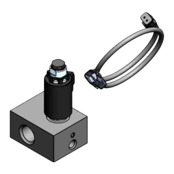
Fig. 6 Electric vent valve (16) -
Page 9: Ac Pump On 120 Lbs (54 Kg) Drum
Fig. IPB 1 AC pump on 120 lbs (54 kg) drum 23, 24... -
Page 10: Ac Pump On 400 Lbs (181 Kg) Drum
Fig. IPB 2 AC pump on 400 lbs (181 kg) drum 23, 24... -
Page 11: Dc Pump On 120 Lbs (54 Kg) Drum
Fig. IPB 3 DC pump on 120 lbs (54 kg) drum 23, 24... -
Page 12: Dc Pump On 400 Lbs (181 Kg) Drum
Fig. IPB 4 DC pump on 400 lbs (181 kg) drum 23, 24... -
Page 13: Parts List
Vent valve body Seal kit for item 30 Non-common repair parts Part number Model Power Drum Vent tube Solenoid valve 85831 230 V AC 120 lb. (54 kg) 67290 279048 85832 230 V AC 400 lb. (181 kg) 67241 279048... - Page 14 This page left intentionally blank...
- Page 15 This page left intentionally blank...
-
Page 16: Warranty
® SKF and Lincoln are registered trademarks of the SKF Group. © SKF Group 2021 The contents of this publication are the copyright of the publisher and may not be reproduced (even extracts) unless prior written permission is granted. Every care has been taken to ensure the accuracy of the information contained in this publication but no liability can be accepted for any loss or damage whether direct, indirect or consequential arising out of the use of the information contained herein.
Need help?
Do you have a question about the 85831 and is the answer not in the manual?
Questions and answers