Table of Contents
Advertisement
Quick Links
Advertisement
Table of Contents

Related Manuals for Control KSUE

Summary of Contents for Control KSUE
- Page 1 KSUE Control and monitoring unit MANUAL...
-
Page 2: Table Of Contents
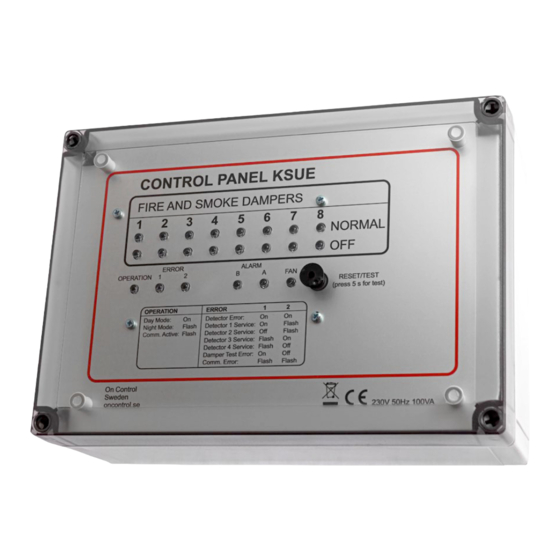
Terminology ....................10 Operating instructions/troubleshooting .............11 DESCRIPTION The KSUE is a control and monitoring unit for fire protection in ventilation systems, intended to control fire dampers and an air handling unit (fan). The unit regularly monitors the damper’s end positions. The unit can be used as a fully stand-alone unit or as a slave unit in networks with the SUSA or KSUA master unit. -
Page 3: General System Overview
GENERAL SYSTEM OVERVIEW The following diagram is a typical example of network mode between the SUSA master unit and slave units. Follow the instructions to install the KSUE as a stand-alone unit or as a slave unit for the SUSA or KSUA. -
Page 4: Terminals
G0 M Ö S G0 M Ö S G0 M Ö S G0 M Ö S DET1 DET2 DET3 DET4 NIGHT A-Alarm B-Alarm Fan Control DAMPER 1 DAMPER 3 DAMPER 5 DAMPER 7 9 10 11 12 13 14 15... -
Page 5: Damper Wiring
A bypass/pressure relief damper type with spring return to the open position can only be handled if the KSUE is used as a slave unit and the damper type is connected as a fire damper. The damper types must not be mixed within the same damper group. -
Page 6: Wiring In Stand-Alone Mode
DAMPER 1 DAMPER 3 DAMPER 5 DAMPER 7 DET1 DET2 DET3 DET4 NIGHT A-Alarm B-Alarm Fan Control 9 10 11 12 13 14 15 16 17 18 19 20 21 IMPORTANT! DAMPER 2 DAMPER 4 DAMPER 6 DAMPER 8 TERM... - Page 7 WIRING IN STAND-ALONE MODE INPUTS TERMINAL NAME DESCRIPTION FUNCTION WITH FUNCTION WITH JUMPER ON JUMPER OFF Smoke B 4 detector zones 1 detector zone 3(-), 4(+) DET 1 Replace existing resistor detector with smoke detector of DET 1 affects 5(-), 6(+) DET 2 type UG3-0 or similar.
-
Page 8: Wiring In Network Mode
1 2 4 8 16 be connected to IS-BUS. Daisy chaining between units with Gnd to Gnd, A to A and B to B. Addressing in the KSUE is as shown in the table above. 1 2 4 8 16... -
Page 9: Specification
SPECIFICATION Installation Inputs Intended to be attached to a wall. IS network bus to SUSA or KSUA master unit. External fire alarm (EXT). Affects all damper groups. Power supply Night mode input (NIGHT) or damper test input (CLK) 230 VAC, 50 Hz, 100 VA. Protected with 2 A fuse at Detector 1. -
Page 10: Terminology
TERMINOLOGY Ventilation damper A fire damper with a 24 VAC motor. It closes with spring force to the fail-safe position (closed). Evacuation/ A damper with a 24 VAC motor. It opens with spring force to the fail-safe position (open). pressure relief/ bypass damper Normal mode Ventilation dampers are open and evacuation dampers are closed. -
Page 11: Operating Instructions/Troubleshooting
That the fuse to the damper outputs is intact (4 AT) If the air handling unit moves to the fire position during the automatic damper test. Check that FAN CONTROL is connected to the correct input on the unit, marked external stop or similar. B OPERATION Green LED showing that the unit is energised and indicating day/night mode or communication. - Page 12 Communication loop from Gnd to Gnd, A to A and B to B between the units. D FAN Normal mode for the air handling unit is indicated with the green LED FAN (CONTROL) when the CONTROL relay is closed 19-21.
- Page 13 FUNCTION DESCRIPTION A ALARM The A alarm (fire) is indicated by the red LED and the associated relay output is closed when the following events occur. Smoke detected by one of the detector loops (DET 1-4) Break of EXT input (external fire alarm) Check: That the EXT input is jumpered or closed by an external monitoring unit That none of the detector loops is short-circuited...
- Page 14 PROFCON AB Victor Hasselblads gata 9 421 31 Västra Frölunda Sweden Tel: +46 (0)33 25 65 70 Web: oncontrol.se On Control is a registered trade mark of PROFCON AB MANUAL v5.02 14 / 14...
Need help?
Do you have a question about the KSUE and is the answer not in the manual?
Questions and answers