Table of Contents
Advertisement
Advertisement
Table of Contents

Subscribe to Our Youtube Channel
Related Manuals for DigiTech QC1938


Summary of Contents for DigiTech QC1938
-
Page 1: Qc1938 Digital Storage Oscilloscope
User Manual QC1938 Digital Storage Oscilloscope... -
Page 2: Copyright Declaration
D igitech . Digitech reserves all rights to modify this document without prior notice. Please contact digitech for the latest version of this document before placing an order. Digitech has made every effort to ensure the accuracy of this document but does not guarantee the absence of errors. -
Page 3: General Safety Summary
User Manual General Safety Summary Read the following safety precautions to avoid injury and prevent damage to this product or any products connected to it. To evade potential hazards, use this product only as specified. Only qualified personnel should perform maintenance. Avoid fire or personal injury. -
Page 4: Safety Terms And Symbols
User Manual Safety Terms and Symbols Terms on the product. The following terms may appear on the product: Danger It represents that harms may be caused to you at once if you perform the operation. Warning It represents that latent harms may be caused to you if you perform the operation. Notice It represents the damage possibly caused to the product or other properties if you perform the operation. -
Page 5: Table Of Contents
Copyright Declaration.................................2 General Safety Summary................................3 Safety Terms and Symbols................................. 4 Product Scrapping..................................4 Contents......................................5 QC1938 digital storage oscilloscope introduction........................8 1. Quick start....................................9 1.1. General Inspection................................9 1.2. Prepare Instrument for Use..............................9 1.3. Brief Introduction of Front Panel............................9 1.4. The user interface................................11 1.5. - Page 6 User Manual 2.7.1. Edge Trigger................................22 2.7.2. Pulse Trigger................................23 2.7.3. Video Trigger................................24 2.7.4. Slope Trigger................................25 2.7.5. Overtime Trigger..............................26 2.7.6. Window Trigger............................... 26 2.7.7. Pattern Trigger................................ 27 2.7.8. Interval Trigger................................29 2.7.9. Under Amp Trigger..............................29 2.7.10. UART Trigger................................ 30 2.7.11.
- Page 7 User Manual 2.12. Acquire..................................48 2.12.1. Run Control................................48 2.13. Display................................... 49 2.14. Utility System................................50 2.14.1. Update Firmware..............................50 2.14.2. Self Calibration..............................50 2.14.3. Pass/Fail................................50 2.15. Fast Action Buttons............................... 51 2.15.1. AUTO SCALE................................ 51 2.15.2. Default Setup................................52 2.15.3. Dual-window Mode..............................53 3. Waveform Generator................................54 3.1.
-
Page 8: Qc1938 Digital Storage Oscilloscope Introduction
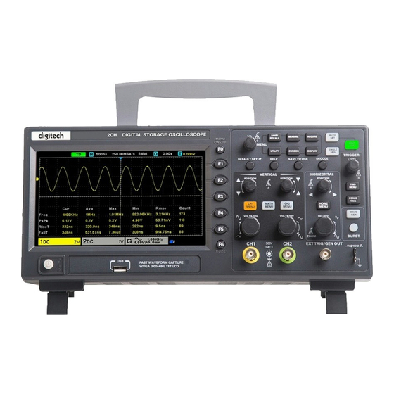
QC1938 digital storage oscilloscope introduction QC1938 oscilloscopes provide a bandwidth of 100MHz and a sampling rate of 1GSa/s. The 7-inch color TFT LCD screen, similar to the Windows-style interface and menus, allows every user familiar with the computer to easily get started. -
Page 9: Quick Start
User Manual 1. Quick start 1.1. General Inspection Please check the instrument as following steps after receiving an oscilloscope: Check the shipping container for damage: Keep the damaged shipping container or cushioning material until the contents of the shipment have been checked for completeness and the instrument has been checked mechanically and electrically. - Page 10 User Manual Power button Bracket USB interface Menu selection key Vertical control system CH1、CH2 Input Channel for signal Horizontal control system Signal source output (only valid for model with function generator) /external trigger input channel Probe compensation function zone 10. Signal source (only valid for model with function generator) 11.
-
Page 11: The User Interface
1.4. The user interface This section will make you understand the front operation panel of this digital oscilloscope at first before use. digitech logo. Trigger Status. AUTO: The oscilloscope works in auto mode and is acquiring waveform in the absence of triggers. -
Page 12: Functional Check
User Manual 1.5. Functional Check Follow the steps below to perform a quick functional check to your oscilloscope. 1.5.1. Connect the oscilloscope Set the switch on the probe to X 10 and connect the probe to Channel 1 on the oscilloscope. First, align the slot in the probe connector with the protuberance on the CH1 BNC and push to connect;... -
Page 13: Manual Probe Compensation
User Manual 1.6.2. Manual Probe Compensation Upon the first connection of a probe and an input channel, you should manually perform this adjustment to match the probe to the input channel. Uncompensated or miscompensated probes may lead to errors or faults in measurement. To adjust the probe compensation, follow the steps below. -
Page 14: Function Introduction
User Manual 2. Function Introduction This chapter provides some general information that you need to learn before using an oscilloscope. It contains: 2.1. Menu and Control Keys As shown in the figure below: All the keys are described as follows: Menu keys [SAVE/RECALL]: "Save/Recall"... -
Page 15: Connector
User Manual Shortcut keys [DEFAULT SETUP]: Recall the default factory setup. [HELP]: View the "Help" message and press this key again to exit the help. [SAVE TO USB]: Press to quickly save the screenshot to the USB disk. Insert the USB disk before use. ... -
Page 16: Multi-Function Knobs And Softkeys
User Manual channels of the oscilloscope. 2.3. Multi-function Knobs and Softkeys V0: Multifunctional knob. Under different menu items (specifically see the operation of each menu), support menu item selection, cursor movement, level movement; press the knob to select menu, data reset (trigger holdoff time), And rotate to change the data bit, etc., the operation is extremely convenient. -
Page 17: Vertical System
User Manual waveform will expand or contract to the screen center. The readout near the upper right of the screen shows the current horizontal position in second. The oscilloscope also has an arrow icon at the top of the graticule to indicate the horizontal position. -
Page 18: Math Operation
User Manual Vertical offset knob Volts/DIV knob 1. Vertical Offset Knob: Move the channel waveform up and down on the screen. In dual-window mode, move the waveform in both windows at the same time in a same direction. Push this knob to return waveform to the vertical center position on the screen. - Page 19 User Manual division (/) None dB, VRms Addition or Subtraction Math operators perform arithmetic operations - add or subtract operation - on any two analog input channels. When you select addition or subtraction, the Source A and Source B values are added or subtracted point by point, and the result is displayed.
- Page 20 User Manual FFT is used to compute the fast Fourier transform using analog input channels or reference waveform. FFT takes the digitized time record of the specified source and transforms it to the frequency domain. When the FFT function is selected, the FFT spectrum is plotted on the oscilloscope display as magnitude in dBV versus frequency.
-
Page 21: Trigger System
User Manual Flattop Periodic Waveform Better amplitude, poorer frequency accuracy than Hanning 9. Press the Show-Only softkey to select to display FFT operation results only and not display the source channel. Note: 1. Signals with DC components or deviation would cause an error or deviation of the FFT waveform components. To reduce the DC components, set the Channel Coupling to AC. -
Page 22: Edge Trigger
User Manual be used to generate a stable display of complex waveform (such as pulse trains). Holdoff is the time between when the oscilloscope detects one trigger and when it is ready to detect another. During the holdoff time, the oscilloscope will not trigger. -
Page 23: Pulse Trigger
User Manual complex waveforms are displayed stably. Note: Press the [Auto Set] button will set the trigger type to Edge and slope to rising. 2.7.2. Pulse Trigger Pulse trigger sets the oscilloscope to trigger on a positive or negative pulse of a specified width. You can set the trigger source, polarity (positive pulse width, negative pulse width), limit conditions, and pulse width in this menu. -
Page 24: Video Trigger
User Manual = (equal to time value): trigger when the positive or negative slope time of the input signal is equal to the specified time value. For example, for a positive pulse, if you set t (pulse real width) = 200ns, the waveform will trigger. 7. -
Page 25: Slope Trigger
User Manual is not met, it can run the acquisition waveform freely. Normal: When the oscilloscope meets the trigger condition, the input waveform is displayed; when the trigger condition is not met, the original waveform is displayed. 9. Press the Holdoff softkey and turn V0 to set the time that the oscilloscope waits before a trigger to the next trigger, so that complex waveforms are displayed stably. -
Page 26: Overtime Trigger
User Manual 8. Press the Mode softkey, turn V0 to select the trigger mode (auto, normal), and press V0 to confirm. Auto: When the oscilloscope meets the trigger condition, it completes a trigger acquisition once; when the trigger condition is not met, it can run the acquisition waveform freely. Normal: When the oscilloscope meets the trigger condition, the input waveform is displayed;... -
Page 27: Pattern Trigger
User Manual If the lower and the upper trigger levels are both within the waveform amplitude range, the oscilloscope will trigger on both rising and falling edge. If the upper trigger level is within the waveform amplitude range while the lower trigger level is out of the waveform ... - Page 28 User Manual To set interval trigger: 1. Press the [Trig Menu] button on the front panel to enter the Trigger system function menu. 2. Press the Type softkey, then use the Multifunctional Knob to select Pattern and push down the knob to confirm. 3.
-
Page 29: Interval Trigger
User Manual complex waveforms are displayed stably. 2.7.8. Interval Trigger Trigger when the time difference between the neighboring rising or falling edges meets the time limit condition (<, >, !=, =). To set interval trigger: 1. Press the [Trig Menu] button on the front panel to enter the Trigger system function menu. 2. -
Page 30: Uart Trigger
User Manual A positive under Amp pulse across through a lower threshold but not an upper threshold. A negative under Amp pulse across through an upper threshold but not a lower threshold. To trigger on under Amp pulse: 1. -
Page 31: Lin Trigger
User Manual press the Custom softkey and turn the Multifunctional Knob to set the desired baud rate. Parity: Parity Check. Choose odd, even, or none, based on your device under test. Data Bits: Data Length, Set the number of bits to match your device under test. (selectable from 5-8 bits). ... -
Page 32: Can Trigger
User Manual 3. Press the Source softkey, turn the Multifunctional Knob to select CH1~CH2 as the trigger source. 4. Press the Buad Tate softkey, and turn the Multifunctional Knob to set the Baud Rate. 5. Press the Idle Level softkey, and turn the Multifunctional Knob to set the Idle Level. 6. -
Page 33: Spi Trigger
User Manual Note: The Identifier means Remote ID and Data ID. 7. Press When softkey to set trigger condition. Start: The oscilloscope triggers at the start of a frame. Remote ID: The oscilloscope triggers on remote frames with the specified ID. ... -
Page 34: Iic Trigger
User Manual 4. Data Line Setting: Press Data Width to set the number of bits of the serial data character string. The serial data string can be specified to be from 4, 8, 16, 24, 32 bits long. Press Data softkey, use V0 to set the data, refer to 2.7.10. Data Mask: it is hexadecimal, 0-Mask, f-No Mask, 1~e mask some data. -
Page 35: Protocol Decode
User Manual Start: trigger when SDA data transitions from high level to low level while SCL is high level. Stop: trigger when SDA data transitions from low level to high level while SCL is high level. No Ack: trigger when the SDA data is high level during any acknowledgement of SCL clock position. ... -
Page 36: Lin Decode
User Manual UART Decode interpretation: 1. The decode data is displayed in hexadecimal; 2. The decoded data is at the bottom of the waveform interface by default, and displayed in purple; 3. When there are "?" or "adjust the time base", you need to adjust the time base to see the decoding results. UART text interface is shown as below: 2.8.2. -
Page 37: Can Decode
User Manual LIN Decode interpretation: 1. The decode data is displayed in hexadecimal; 2. The decoded data is at the bottom of the waveform interface by default. The color of "Frame ID" and "Checksum" is purple, and the color of "Data" is blue; 3. -
Page 38: Spi Decode
User Manual CAN Decode interpretation: 1. The decode data is displayed in hexadecimal; 2. The decoded data is at the bottom of the waveform interface. The color of “frame ID” is displayed purple, the “Data” is blue, the “CRC” is purple; 3. -
Page 39: Iic Decode
User Manual The trigger result is shown below: SPI Decode interpretation: 1. The decode data is displayed in hexadecimal; 2. The decoded data is at the bottom of the waveform interface. The color of “Data” is displayed purple; 3. When there are "?" or "adjust the time base", you need to adjust the time base to see the decoding results. SPI text interface is shown as below: 2.8.5. -
Page 40: Save/Recall
User Manual IIC Decode interpretation: 1. The decode data is displayed in hexadecimal; 2. The decoded data is at the bottom of the waveform interface. The color of “Address” and “Data” are displayed purple; "W" indicates the write operation, "R" indicates the read operation, "D" indicates the decoded data, "~A" indicates the unacknowledged bit;... -
Page 41: Internal Save And Recall
User Manual 1. Setup It’s the default storage type of the scope. It saves the settings of the oscilloscope in internal or external memory in “.set” format. Up to 9 setting files (No.1~No.9) can be stored in the internal memory. The stored settings can be recalled. 2. -
Page 42: Save Picture
User Manual Before using external storage and recall, make sure that the USB storage device is connected correctly. External storage supports all the types of files in save, but in recall, CSV is not supported. 2.9.2.1. Save the setup file to external USB storage device. 1. -
Page 43: File Manager
2.9.4.1. Create a New File This operation is only valid in external storage. QC1938 supports English input method. The file name or folder name can contain letters, numbers and underscores. Let’s use an example to introduce how to create a file or folder. -
Page 44: Measure System
User Manual 2. Press the Type softkey, and then turn the Multifunctional Knob to select one type. 3. Use the SaveTo softkey to external location. Press Save softkey and into File Manager interface. 4. Turn the Multifunctional Knob V0 to select the file or folder, press the Rename softkey, and then refer to the descriptions “Create a new file”... -
Page 45: Automatic Measurement
User Manual AX(BX) A selected cursor is highlighted, which can be moved freely. Both cursors AXBX Select Cursor can be selected and moved at the same time. The box behind the cursor AY(BY) displays the location of the cursor. AYBY Moving Cursors: Press the key near Select Cursor to select a cursor and turn Multifunctional Knob to move it. - Page 46 User Manual Make statistic and display the current, average, minimum, maximum, root mean square error and count values of at most 4 measurement items that are turned on last. 1. Press the [Meas] button on the front panel to enter the Measure function menu. 2.
-
Page 47: Dvm
User Manual FallTime Measure the time between 90% and 10% of the first falling edge of the waveform. Measure the time between the first rising edge and the next falling edge at the waveform 50% + Width level. Measure the time between the first falling edge and the next rising edge at the waveform 50% - Width level. -
Page 48: Acquire
User Manual performed when the oscilloscope is running or stopped. Press [MEASURE] on the front panel to enter the measurement interface, and press F3 to select the DVM to enter DVM setting interface. Press CH1 Enable, CH2 Enable to enable any channel or all channels of DVM. Press CH1 Type, CH2 Type to select the data type displayed by DVM. -
Page 49: Display
User Manual should use the Peak Detect mode to acquire data. Peak Detect: In this acquisition mode, the oscilloscope gets the maximum and minimum values of the input signal over each sample interval and uses these values to display the waveform. In this way, the oscilloscope can acquire and display those narrow pulses that may have otherwise been missed in Normal mode. -
Page 50: Utility System
User Manual Brightness Persist Infinite Sets the time length to display each displayed sample point. 1s, 5s, 10s,30s 2.14. Utility System Push the UTILITY button to display the Utility Menu as follows. Options Comments Language Set the language Sound Set the buzzer. Update Insert a USB disk with upgrade program. -
Page 51: Fast Action Buttons
User Manual Option Setup Description Pass/Fail ON/OFF Run/Stop the pass/fail function. Source CH1~CH2 Select the signal input channel. Use the Multifunctional Knob to set a horizontal tolerance range: Vertical 0.020div-4.00div. Use the Multifunctional Knob to set a vertical tolerance range: Horizontal 0.025div-8.00div. -
Page 52: Default Setup
User Manual Functions Settings Acquire Mode Adjusted to Normal or Peak Detect Cursor Display Format Set to YT Display Type Set to Vectors for an FFT spectrum; otherwise, unchanged Horizontal Position Adjusted SEC/DIV Adjusted Trigger Coupling Adjusted to DC, Noise Reject or HF Reject Trigger Holdoff Minimum Trigger Level... -
Page 53: Dual-Window Mode
User Manual Operating status Run/Stop Cursor State Type Vectors Display Persist Display Mode Window Mode Single-window Trigger Knob Level Horizontal Position 0.00s SEC/DIV 200μs Math Status Measure Status Type Edge Source Trigger (Edge) Slope Rising Mode Auto Level 0.00v Bandwidth Limit Unlimited VOLTS/DIV Coarse... -
Page 54: Waveform Generator
User Manual Dual-window Mode 3. Waveform Generator The oscilloscope is equipped with waveform generator function, with one channel of arbitrary waveform output. User can edit the arbitrary waveform or choose the regular waveform such as Sine, Ramp, Square, Exponent, Noise, DC and Arb waveform. -
Page 55: Waveform Modulation Setting
User Manual turn the Multifunctional Knob to set the value. 4. Press the Amplitude softkey to set amplitude, press this key repeatedly to set the High Level (Offset automatically switches to low level) or Amplitude /High Level fine, and turn the Multifunctional Knob to set the value. 5. -
Page 56: Edit Arbitrary Waveform
User Manual The data source is specified as manual. Press Burst to output a burst with a specified number of cycles. 3.4. Edit Arbitrary Waveform Double click “WaveEditor.exe” in WaveEditor folder in CD disk to enter arbitrary waveform generator window. Menu: Import from CSV: Import the CSV format file to the arbitrary waveform generator window. -
Page 57: Output Arbitrary Waveform
User Manual : Cycles. The number of cycles to draw. This control is used in conjunction with the Standard waveform shapes buttons. Select one of the standard waveform shapes and then enter the number of cycles, and it will draw the requested number of cycles of the waveform. -
Page 58: Remote Control
User Manual Press Recall softkey and select desired recalled ARB format file in USB disk. The waveform will output from GEN OUT BNC port. 4. Remote Control Connect the Type-A end of the USB cable to the computer, and connect the Type-B end to the USB port on the back of the oscilloscope. - Page 59 User Manual After installation, you can see the running IO software in the lower right corner of the screen. Double-click to open the IO software, you can see the connected device information displayed under My Instrument-USB. Click "Interactive IO", send an instruction arbitrarily, and the computer and the oscilloscope will communicate. 59 / 76...
-
Page 60: Troubleshooting
2) Check the power on/off button to ensure it has been pushed; 3) Then restart the oscilloscope. digitech distributor or directly keep touch with digitech Technical Support department if the oscilloscope Contact your local still can not be turned on normally. -
Page 61: Open Source Information
User Manual 1) Check the probe to assure its proper connection to the channel BNC; 2) Check the probe to assure its good connection to the measured object; 3) Check the probe to verify it has been well calibrated. Otherwise, refer to the content about calibration described in this manual. -
Page 62: Appendix A: Technical Specifications
Note: To avoid damage to the surface of the oscilloscope or probes, do not use any corrosive or chemical cleaning agents. Appendix A: Technical Specifications All technical specifications are applicable to QC1938 digital storage oscilloscopes, see the last part of this chapter for details. To verify whether the oscilloscope meets the technical specifications, the oscilloscope must first meet the following conditions: ... - Page 63 User Manual Acquisition Sample Rate Range 1GS/s (Single-channel); 500MSa/s (Dual-channel); Equivalent sampling 50GSa/s Acquisition Modes Normal, Peak, Average and High Resolution Waveform Interpolation (sin x)/x Up to 2000 waveform per second per channel (Normal acquisition mode, no Acquisition Rate, typical measurement) Minimum detection pulse width Acquisition Mode...
- Page 64 User Manual Time Range 8ns ~ 10s Overtime Trigger Source CH1~CH2 Polarity Positive, Negative Time Range 8ns ~ 10s Window Trigger Source CH1~CH2 Pattern Trigger Pattern 0: Lower level; 1: High level; X: Ignore; : Rise; : Fall; : Rise or fall. Level CH1~CH2 Interval Trigger...
- Page 65 User Manual 400 bit/s Baud Rate (Custom) 300bit/s~334000bit/s CAN Trigger Start Bit, Remote Frame, Data Frame Id, Frame Id, DataFrame Id A, Error Frame, All Error, Condition Ack Error, Overload Fram Source CH1~CH2 Data format 10000, 20000, 33300, 500000, 62500, 83300, 100000, 125000, 250000, 500000, 800000, Baud Rate (Selectable) 1000000 Baud Rate (Custom)
- Page 66 User Manual Frequency Meter Hardware 6 bits Math operation Source CH1~CH2 Operator +, -, x, /, FFT Point 1024 Window Rectangle, Hanning, Hamming, Blackman, Bartlett, Flattop Display Show only or show all Vertical scale dB, VRms Storage 9 types of files can be saved and recalled internally, including settings, waveforms, and Save/recall (non-volatile) references Save to external memory...
-
Page 67: Appendix B: Accessories
5Hz to 500Hz, 10 minutes on each axis Mechanical Shock Operating 50g, 11ms, half sine Mechanical Dimension 318 x 110 x 150mm (L x W x H) Weight 1900g Appendix B: Accessories digitech distributor. All the following accessories are available by contacting your local 67 / 76... -
Page 68: Appendix C: Harmful And Poisonous Substances Or Elements
User Manual Standard Accessories A Passive Probe (1.5m, 10:1) Two Test Leads with two clips A Power Line A USB Line A PC Software CD of the oscilloscope Appendix C: Harmful and Poisonous Substances or Elements Harmful and poisonous substances or elements Component Cr (Vi) - Page 69 User Manual The licenses for most software are designed to take away your freedom to share and change it. By contrast, the GNU General Public License is intended to guarantee your freedom to share and change free software--to make sure the software is free for all its users.
- Page 70 User Manual 0. This License applies to any program or other work which contains a notice placed by the copyright holder saying it may be distributed under the terms of this General Public License. The "Program", below, refers to any such program or work, and a "work based on the Program"...
- Page 71 User Manual These requirements apply to the modified work as a whole. If identifiable sections of that work are not derived from the Program, and can be reasonably considered independent and separate works in themselves, then this License, and its terms, do not apply to those sections when you distribute them as separate works.
- Page 72 User Manual If distribution of executable or object code is made by offering access to copy from a designated place, then offering equivalent access to copy the source code from the same place counts as distribution of the source code, even though third parties are not compelled to copy the source along with the object code. 4.
- Page 73 User Manual application of that system; it is up to the author/donor to decide if he or she is willing to distribute software through any other system and a licensee cannot impose that choice. This section is intended to make thoroughly clear what is believed to be a consequence of the rest of this License. 8.
- Page 74 User Manual AS PERMITTED ABOVE, BE LIABLE TO YOU FOR DAMAGES, INCLUDING ANY GENERAL, SPECIAL, INCIDENTAL OR CONSEQUENTIAL DAMAGES ARISING OUT OF THE USE OR INABILITY TO USE THE PROGRAM (INCLUDING BUT NOT LIMITED TO LOSS OF DATA OR DATA BEING RENDERED INACCURATE OR LOSSES SUSTAINED BY YOU OR THIRD PARTIES OR A FAILURE OF THE PROGRAM TO OPERATE WITH ANY OTHER PROGRAMS), EVEN IF SUCH HOLDER OR OTHER PARTY HAS BEEN ADVISED OF THE POSSIBILITY OF SUCH DAMAGES.
- Page 75 User Manual Gnomovision version 69, Copyright (C) year name of author Gnomovision comes with ABSOLUTELY NO WARRANTY; for details type `show w'. This is free software, and you are welcome to redistribute it under certain conditions; type `show c' for details. The hypothetical commands `show w' and `show c' should show the appropriate parts of the General Public License.
- Page 76 User Manual Distributed by: TechBrands by Electus Distribution Pty. Ltd. 320 Victoria Rd, Rydalmere NSW 2116 Australia Ph: 1300 738 555 Int’l: +61 2 8832 3200 Fax: 1300 738 500 www.techbrands.com Made in China 76 / 76...
Need help?
Do you have a question about the QC1938 and is the answer not in the manual?
Questions and answers