Table of Contents
Advertisement
Quick Links
Advertisement
Table of Contents

Related Manuals for Melco EMT16X


Summary of Contents for Melco EMT16X
- Page 1 EMT16X Technical Manual Rev 113020...
- Page 2 Contents Copyright Notice About This Manual Scope of Manual Standard Conventions and Definition of Terms Regulatory Notices Best Maintenance Repair Practices Maintenance Philosophy: Grounding and Static Electricity Machine Orientation Safety Issues Warranty Considerations Explanation of Machine Symbols Keypad Operations Head Timing Keypad Functions Keypad Buttons Trace Button Arrow Up Key (Y-Axis Back)
- Page 3 Software Maintenance Menus Special Tools and Fixtures General Maintenance Cleaning Lubrication Schedule and Specifications Maintenance Schedule Daily Maintenance Weekly Maintenance Monthly Maintenance Quarterly Maintenance Head Up Position Adjustment Mechanical Head-Up Position Adjusting Head-Up (Z-Home) Position: Hook Timing Inspection/Adjustment Rotational Hook Timing Inspection Procedure Needle To Hook Gap Inspection Procedure Adjustment Procedure Trimmer Replacement...
- Page 4 Z-TIMING: Bottom Center & Head-Up Bottom Center (Z Timing) Z-Drive Belt Tensioning Inspection and Adjustment Z-Home Adjustment Procedure to Identify the Closest Needle Needle Case Calibration Fine calibration procedure: Rough Calibration Process: Rotary Hook Support Adjustment Inspection Procedure Adjustment Procedure Color Change, Take-Up, Feeder Housing Assembly Replacement Procedure for Entire Color Change/Take-Up/Feeder Assembly: Color Change Linear Actuator Replacement...
- Page 5 Z-Belt Idler Assembly Replacement Z-Motor Assembly Clearing Thread from Thread Feeder Roller Color Change Spindle Mounting Bracket Replacement Grabber Blade Replacement Needle Case Removal Needlecase Installation Grabber Stepper Motor Replacement Take Up Lever Replacement Thread Feeder (replacement and adjustment) Thread Sensor Assembly Replacement Bobbin Shaft Overhaul Rotary Hook Replacement Main PCB...
- Page 6 User Interface Harness X/Y Home Harness Bearing Block Assemblies X-Beam Assembly X-Carriage Assembly X-Drive Cable Removal X-Drive Cable Installation X-Drive Motor Replacement X-Home Optical Switch Assembly Replacement X/Y Home PCB Replacement Y-Drive Belt Replacement Y-Motor Assembly Troubleshooting Grabber Function Test Final Functional Tests Optical Sensors Test Power Supply Test...
- Page 7 Electrical Failures Color Change Failures LED Cluster Assembly Failures Mechanical Failures False Thread Breaks Loose/Looping Stitches Needle Breaks Skipped Stitches Thread Breaks Miss-Starts Cap Frame Issues Miscellaneous Problems X-Axis Failures Y-Axis Failures Z-Axis Failures Software Error Messages DSP Command Errors Can’t Initialize Stepper Motors No Trace Data XY Home Not Set...
- Page 8 Critical Measurements Introduction Needle Drive Stud to Reciprocator Fit Hook Timing Upper Arm to Lower Bed Alignment Needle to Hook Gap Hook to Rotary Support Gap Take-Up Lever Stroke Take-Up Lever Fit to Shaft Take-Up Lever Endplay Cam Follower Preload Pull Force on Take-Up Lever Color Change Lead Screw Color Change Housing Location...
-
Page 9: Copyright Notice
Copyright Notice © Copyright Melco, 2020 ALL RIGHTS RESERVED. No part of this publication may be reproduced, stored in a retrieval system, or transmitted in any form or by any means (electronic, mechanical, photocopying, recording or otherwise) without prior written approval from the author. The author reserves the right to revise this publication and to make changes in it at any time without obligation of the author to notify any person or organiza- tion of such revisions or changes. -
Page 10: About This Manual
About This Manual This manual contains instructions on repairs and adjustments to the embroidery machine, in addition to other technical information. If you do not fully understand any information in this manual, you are advised to contact your local au- thorized technical support provider for assistance. -
Page 11: Scope Of Manual
• Note: This manual is written for individuals with adequate knowledge, Melco certified training or equivalent and experience in the use of tools required. No attempt is made to explain how to use tools required to make repairs to the machine other than graphical depictions within the procedures involved. -
Page 12: Standard Conventions And Definition Of Terms
Standard Conventions and Definition of Terms Throughout this manual abbreviations and specific terms may be used. When abbreviations or techni- cal terms are used, they are defined through the use of pop-up hot spots, which opens a dialog box to explain their meaning. -
Page 13: Regulatory Notices
Regulatory Notices (U.S.) The FCC (Federal Communications Commission) mandates that if a user makes changes or modi- fications to the machine not expressly approved by the manufacturer, the user’s authority to operate the machine may be voided. 13 of 289 Table of Contents Critical Measurements... -
Page 14: Best Maintenance Repair Practices
Best Maintenance Repair Practices The procedures presented in this manual are to be considered best maintenance repair practices. These procedures are intended to optimize the performance and durability of your machine. Best maintenance repair practices are to be performed using the correct tools and fixtures while adhering to all safety pre- cautions appropriate for each job. - Page 15 Using compressed air, blow the dust away from sensors and off the PCB’s in the machine. In addition, minimize dust accumulation cleaned on all exposed surfaces. Excessive dust will reduce the useful life span of the machine. Sensors should be cleaned with dry, compressed air during each of the lubrication cycles. Dust accumula- tion in the base around the control PCB should be blown out every month or whenever the base cover is removed for any type of maintenance.
-
Page 16: Scheduled Maintenance
Drive Belt Tensions: • CAUTION! Damage to the machine may result if belt tensions are improperly adjusted. All drive belts require special procedures and tools for setting the proper tensions. If the tension adjust- ments are made without using the proper procedures and tools (and without training in some cases), poor performance, excessive wear, damaged components, personal injury, and voided warranty may result. -
Page 17: Grounding And Static Electricity
Grounding and Static Electricity • WARNING!! It is very important that the power cord is plugged into a properly wired electri- cal outlet. Failure to have a properly wired outlet may result in damage to the equipment and personal injury. It is recommended that a licensed electrician be consulted to ensure that the electrical outlet is properly wired and grounded. - Page 18 • CAUTION !! Use extreme care not to damage the cable and protective coating during assem- bly. If the protective coating is damaged, the cable will wear out very fast impacting the quality of the sew outs. 18 of 289 Table of Contents Critical Measurements...
-
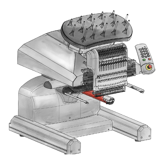
Page 19: Machine Orientation
Machine Orientation The references in the manual to certain sections of the machine are oriented as if you were facing the front of the machine as shown below. Example: The “left” arm cover is on the left side of the machine when you face it from the front, but is on the right side if you face it from the rear. - Page 20 Safety Issues Voltages • WARNING!! Lethal voltages exist inside the power supply unit, at the back side of the electrical supply input connector, and in the wires between the two. If you plan to do any work with any of these components, turn the power switch off and disconnect the electrical input supply cord from the machine.
-
Page 21: Warranty Considerations
Warranty Considerations Many areas of maintenance in this manual require factory trained personnel to ensure proper service. Any service that is improperly performed may void the warranty. Items that are marked “...should be done by an authorized service technician” should be performed by a repair technician that has been authorized by the manufacturer. -
Page 22: Explanation Of Machine Symbols
Explanation of Machine Symbols These labels are placed on the machine at specified locations to warn you of certain machine hazards. Caution!! Indicates a machine component will move. Keep clear! Shock Hazard. No user replaceable parts behind this label. Do not open! Moving gears. -
Page 23: Keypad Operations
Keypad Operations Function Press these key(s) Keypad Pictures Notes To Start Sewing Start Press the stop key to stop sewing To Stop Sewing Stop Press the start key to start sewing Cuts power to the Emergency Stop To release, turn a quar- motors. - Page 24 Function Press these key(s) Keypad Pictures Notes To move the hoop down Hoop + Right + Up Always trace after and to the left (moves moving needle position up and to the right in relation to the hoop) To move the hoop up Hoop + Right + Down Always trace after and to the left (moves...
- Page 25 Function Press these key(s) Keypad Pictures Notes To move the needlecase Needlecase key + Left to the left Arrow To color change to the Needlecase key + Up next color Arrow To color change to the Needlecase key + Down previous color Arrow To turn the laser on...
- Page 26 Head Timing Keypad Functions When the Head Timing tab is open in the software, several special keypad functions are available. These keypad functions are only available when the Head Timing tab is open. The following table describes these functions. Go To Head Up Position Adjustment Key + Up Arrow Go To Bottom Center Position Adjustment Key + Down Arrow...
- Page 27 Head Up > Bottom Center (Used for Color Calibration) Frame Back Key Always starts at needle one. When this key is pressed once, machine goes to Head Up position twice, then goes to Bottom Center. When the Frame Back key is pressed again, the machine color changes to the next needle, then goes to Bottom Center on that needle.
-
Page 28: Keypad Buttons
Keypad Buttons Trace Button The trace button is used to trace the design, a method used to help the operator determine if the design is properly centered and fits within the hoop used. To trace a design, press the Hoop button and the Trace button. Arrow Up Key (Y-Axis Back) The needle case moves to the next color. - Page 29 Arrow Right Key (X-Axis Left) The machine performs a “manual jog”, moving stitch point right. The hoop actually moves to the left. The needle case moves to the right. Center Key When used with the hoop key , the machine moves to hoop center. When used with the adjustment key, the machine toggles the safety grabber in and out.
-
Page 30: Step Forward Key
Hoop Key The Hoop key is used to move the position of the needle in relation to the hoop. The Hoop Key and the Arrow Up key move the needle position up, towards the top of the hoop (moves the hoop forward, toward the front of the machine. The Hoop Key and the Arrow Down key move the needle position down, towards the bottom of the hoop (moves the hoop towards the back of the machine). -
Page 31: Emergency Stop Button
Pressing the start button while the machine is stopped will re-start the machineat the stitch number where the machine was stopped. Stop Button The stop button stops the machine operation but does not disconnect electrical supply to the motors and electronics. -
Page 32: Led Indicator
LED Indicator The Status Indicator LED is illuminated when the machine is turned ON. The LED color and whether it is blinking indicates the machine status or if it has a fault. Status Light Condition Definition Action to Take Green (blinking) Machine is on, but no RSA files Start software, check connections loaded yet... -
Page 33: Specifications
Min/Max Sew Speed Flats 300-1400 spm Min/Max Sew Speed Caps 300-1200 spm Stitch Length Range Only Limited by Hoop Size User Interface Melco OS Machine Configuration Up to 6 individual machines, connected by Ethernet Self-Diagnostics Capability Retrieves relevant machine data for troubleshooting... - Page 34 Height 1541mm (60.7”) Depth 944mm (37.2”) Weight 95.4kg (210.3 lbs) Physical Specifications without Cart Width 724mm (28.5”) Height 907mm (35.7”) Depth 737mm (29.0”) Weight 75kg (165lbs) 34 of 289 Table of Contents Critical Measurements...
-
Page 35: Technical Specifications
Technical Specifications The following is a list of various tension and force specifications for your machine. See the Critical Measurements section for other machine specifications that are not listed below. Specification BRECO Meter Measurement Force Gauge Measurement X Drive Cable Tension 145 ±... -
Page 36: Torque Specifications
Torque Specifications The following chart depicts the torque specifications for all screws and nuts used in the machine. They should be followed unless indicated otherwise in this manual (i.e., screws going into plastic materials require lower torque). • Note: Reduce torque specifications when attaching optical sensors by 10% to prevent damage to the sensor housing. - Page 37 Size Zn Plated, Property Class 8.8, Low Profile Socket Head Screws PN: 30750-XX 2.61 3.19 Black Oxide, Property Class 10.9, Flat Head Socket Screws (PN: 001935-XX, 007443-XX) 1.73 2.11 Zn Plated, Property Class 10.9, Flat Head Socket Screws (PN: 011197-XX, 011198-XX) 3.77 4.61 7.29...
-
Page 38: Software Maintenance Menus
Software Maintenance Menus In order to access the maintenance menus in the software, the machine must be turned on and software must be loaded and launched. Figure 1 - Software Main Menu To access the maintenance menu, select the “Tools>Maintenance” from the main menu. The screen be- low will open. -
Page 39: Special Tools And Fixtures
Special Tools and Fixtures The following fixtures and special tools are required to perform certain procedures and repairs described in this manual: • Fixture, Y-Belt Tensioning (PN: 32108) • Force Gauge (0-40 lbs.) (PN: 995595-01) • Force Gauge (0-10 lbs.) (PN: 995591-01) •... -
Page 40: General Maintenance
General Maintenance This section describes the procedures involved in maintaining your machine. This section is very import- ant, because maintenance is essential to the performance of your machine. Cleaning It is very important that you clean your machine regularly. Dust and lint accumulation can damage both electrical and mechanical systems. - Page 41 c. Once the main PCB cover is removed loosen but do not remove the 2 PCB securing tray screws in the front and fully remove the securing plate screw in the rear. d. Gently slide the main PCB mounting tray forward to gain full access to the main PCB. 4.
-
Page 42: Lubrication Schedule And Specifications
Lubrication Schedule and Specifications Tools and supplies needed for these procedures are provided in your operator’s kit. Using the correct lubricants properly and when specified by scheduled maintenance is critical to the operation of the machine. Failure to use the proper lubricants as specified can shorten the usable life of internal components and can void the warranty. - Page 43 Monthly Lubrication Point(s) Lubrication Used X-Drive Rails HP Grease Y-Bearing Blocks Sewing Machine Oil X-Cable Tension (Test) Grabber Eccentric HP Grease Quarterly Lubrication Point(s) Lubrication Used Take-Up Lever Cam, Presser Foot Cam Follower, & HP Grease Right Needle Bar Guide Presser Foot Cam &...
-
Page 44: Daily Maintenance
Daily Maintenance Rotary Hook The rotary hook should be oiled approximately every 4-5 hours of solid running. This will keep the ma- chine running smoother, quieter, and prevent thread breaks. • WARNING!! Never attempt to remove or insert the bobbin with the machine is in operation. 1. - Page 45 5. Using a small oiler bottle, apply one (1) drop of sewing machine oil to the hook oiling area. This area is highlighted in green in the photograph. 6. This is now a good time to clean, rethread, and Insert the bobbin and case into the machine with the pigtail facing up.
-
Page 46: Weekly Maintenance
Weekly Maintenance • WARNING!! If you currently have a hoop or clamping system on the machine, please remove it. Failure to fully remove a clamping system can result in damage to the machine. Needle Drive 1. Color change to Needle 16. 2. - Page 47 Right Upper V-Rail 9. Color change to needle #1. 10. Using a piece of lint-free cloth, wipe clean both the front and back surfaces of the upper v-rail on the RIGHT side of the needlecase. 11. After cleaning the v-rail, use a small oiler bottle to apply a drop of oil each to the front and the back surfaces of the v-rail.
- Page 48 Cleaning Link Area 15. Using a 2.5mm Allen wrench, loosen and remove the two (2) hex head needle plate screws on either side of the bottom of the lower arm as shown in the image. 16. Remove the needle plate from the machine by lifting the needle plate straight up. 17.
- Page 49 Oiling the Trimmer 20. Place a drop of oil on the upper edge of the movable knife. 21. Using the 2.5mm Allen wrench as a pin, move the movable knife back and forth ten (10) times to spread the oil. With compressed air, blow out the needle plate. Using a lint free cloth, wipe the needle plate.
- Page 50 50 of 289 Table of Contents Critical Measurements...
- Page 51 26. Move the needle plate left or right until the needle is centered (left/right) in the needle plate hole as shown in the image. 27. Fully tighten the two (2) hex head needle plate screws. 28. After the needle plate is in place and tightened, release the e-stop by turning the button in the direction of the arrows.
-
Page 52: Monthly Maintenance
Monthly Maintenance X-Drive Rails • WARNING!! If you currently have a hoop or clamping system on the machine, please remove it. Failure to fully remove a clamping system can result in damage to the machine. 1. Move the x-beam all the way forward and all the way to the left using the hoop and the arrow keys on the keypad. - Page 53 6. Remove the end cap cover on the left side of the x-beam as shown in the image. 7. Wipe any lint, dust, and old grease from the front and back steel rails inside the x-beam as shown in the image. 8.
- Page 54 • Note: Not all the screws are the same length. Ensure that you use the same screws for the origi- nal position later in this procedure. 13. Remove the left side cover from the machine. 14. Using a small oiler bottle, place twenty five (25) drops of sewing machine oil into the oiling port as shown in the image.
- Page 55 • Note: Not all the screws are the same length. Ensure that you use the same screws for the origi- nal position later in this procedure. 21. Remove the right side cover from the machine. 22. Using a small oiler bottle, place twenty five (25) drops of sewing machine oil into the oiling port as shown in the image.
- Page 56 • If the x-cable is not positioned within the large cut-out on the right side of the x-cable tension gauge as shown in the image, the tension is out of specification and needs adjustment. a. Remove, but do not discard, the side cover support foam. b.
- Page 57 27. Loosely install one (1) of the rear (shorter) mounting screws to hold the cover in place. 28. Install the other two (2) mounting screws. The longer of the screws secures the front. The shorter of the screws secures the rear. 29.
-
Page 58: Quarterly Maintenance
• IMPORTANT: Ensure that no grease is applied to the black grabber flag on the right side. 34. Once the grease has been applied, release the grabber connecting lever and remove the small screwdriver. This completes the monthly maintenance procedure Quarterly Maintenance Take-Up Lever Cam, Presser Foot Cam Follower, &... - Page 59 6. Using the grease applicator, apply some HP grease to the back surface of the take-up Lever Cam as shown in the image. 7. To gain access to the next maintenance point, the presser foot must be manually raised. Place a finger below the back bend of the presser foot and lift the presser foot as shown in the image.
- Page 60 WARNING!! If you proceed without mounting the right upper arm front cover, damage to your machine will occur and a service call will be necessary. • Note: Melco will not be responsible for any damage to the machine or related service costs caused by not performing this step. 11. Color change to needle #12.
- Page 61 15. With a clean piece of cloth, wipe clean the needle bar guide channel indicated in the image. The image uses cloth wrapped around the grease applicator for better control of the cloth. 16. With a clean piece of cloth, apply a thin film of HP grease to the inside of the channel as shown in the image.
- Page 62 WARNING!! If you proceed without mounting the left upper arm front cover, damage to your machine will occur and a service call will be necessary. • Note: Melco will not be responsible for any damage to the machine or related service costs caused by not performing this step. 24. Color change to needle #5.
- Page 63 26. Color change to needle #15. 27. Now tighten the two (2) remaining screws on the right side of the left upper arm front cover as shown in the image. 28. With a clean piece of cloth, wipe clean the needle bar guide channel indicated in the image. The image uses cloth wrapped around the grease applicator for better control of the cloth.
- Page 64 33. Using two thin-bladed flat screwdrivers or the thread feed gear removal tool, carefully pry the thread feed rollers out of the assembly. This can be accomplished by sliding one screwdriver along each side of the roller and prying against your fingers as shown in the image. Set the rollers to the side.
- Page 65 37. Using the image as a guide, apply three (3) small dots of EMB Polymer grease to the side of the hub. Do this for each side of the thread feed roller. 38. Carefully reinstall the thread feed roller. The gear side of the roller should fall to the left. Align the roller with the slot and gently press forward and down until the roller snaps into place.
- Page 66 42. Next, lower the lever and angle the roller. It can then be pulled forward and free from the ma- chine. If the lever beside the roller is in the way, gentle pressure may be applied to move it slightly out of the way.
- Page 67 48. With one lever up and one lever down, hold the pinch lever at an angle and slide it back into place. 49. Rock it back onto the hub and slowly rotate to begin spreading the grease evenly around the hub. 50.
-
Page 68: Head Up Position Adjustment
Head Up Position Adjustment Mechanical Head-Up Position Figure 1 - Reciprocator Drive Groove at “Head Up” Position Mechanical head up is when the drive slot of the reciprocator (the part that engages the drive stud on the needle bar) is aligned with the needle bar drive slots on the left and right upper arm front covers. Checking Electrical Head-Up (Z-Home) Position: Electrically, head up is correct when the mechanical head up is set and the z-position reading on the Head Timing menu is 26 °... -
Page 69: Adjusting Head-Up (Z-Home) Position
Adjusting Head-Up (Z-Home) Position: • This procedure is performed after Checking Head Up procedures above are completed. This procedure is also referred to as Head Timing. 1. Remove the left arm cover and remove the back screw from the right arm cover. 2. -
Page 70: Hook Timing Inspection/Adjustment
Hook Timing Inspection/Adjustment It is recommended that you read the Head Timing Tab section before performing hook timing inspection/ adjustment. It is possible for the machine rotary hook to slip from the factory-set hook timing. Inadequate timing be- tween the hook and the needle can be one of the causes of upper thread breaks. The following inspec- tion procedure will allow you to check the hook timing of your machine(s). -
Page 71: Rotational Hook Timing Inspection Procedure
Rotational Hook Timing Inspection Procedure 1. Make sure your machine is turned on and Melco OS is running. 2. Engage the emergency stop button (by pushing it in). 3. Push the x-beam all the way to the back of the machine to ensure that the hoop arms will be out of the way during the procedure. -
Page 72: Needle To Hook Gap Inspection Procedure
• If the hook point is not even with the left side of the needle, you will need to perform a hook timing adjustment. Needle To Hook Gap Inspection Procedure 13. You can now inspect the needle to hook gap (front to back position of the rotary hook). The needle to hook gap refers to the gap between the hook point and the needle scarf. -
Page 73: Adjustment Procedure
Adjustment Procedure 1. Open the Tools>Maintenance menu and then click the Head Timing tab. Click the Head Up button (or on the machine keypad, press the Adjustment key and the Up Arrow key. 2. Use the machine keypad to move the needle case to the closest needle noted in the machine base. - Page 74 • NOTE: While adjusting the needle to hook gap and/or hook timing, you should periodically make sure that the z axis position has not changed (check the Current Z Position box). If the z position has changed, repeat steps 4-6 of this procedure. 7.
- Page 75 13. Repeat step 11 and verify hook gap did not change. Repeat steps 9-13 if hook gap is larger than 0.1mm (.004”). 14. You have verified that both the needle to hook gap and the rotational hook timing are correct, re- fer to the Rotary Hook Support Adjustment section of this document to finish adjusting the rotary hook.
- Page 76 Trimmer Replacement NPT Printed Circuit Board Assembly Replacement 1. Disconnect the A/C power input cord and the external Ethernet cable from the back of the machine. • You must disconnect the power before proceeding. 2. Remove the lower arm top cover by removing four (4) M4x12MM Screws. 3.
- Page 77 5. Uninstall the trimmer PCBA by removing the (4) M4x6mm Btn Hd Cap Screws. 6. While making sure the connection labeled K2 is on the left,. install the new trimmer PCBA. 7. On the trimmer PCBA locate the connections labeled K1, K2, K3 and K4 and connect the corris- ponding harnesses.
- Page 78 3. Remove lower arm rear cover (7 M4 Socket head cap screws) 4. On the trimmer PCBA locate the connection labeled K1 (second from left) and disconnect. 5. Remove the mounting M3 low head screw and remove sensor. 6. Install new trimmer sensor. Making sure the flat side is facing down, slide the sensor under the trimmer connecting link.
- Page 79 8. Check the functionality of the trimmer sensor. a. In the OS software go to Tools>Maintenance>Steppers tab. b. The selector column shows the steps of the trim process. c. The color of the “home” button changes color when stepping through the trim process de- pending on the status of the trimmer sensor.
- Page 80 9. Map the sensor. a. Select [Map Sensor] in the Selector column. b. Wait until the values show up in the drop-down menu. c. Values should be 32 ±1 and 52 ±1 (31-33 & 51-53). d. If values do not fall in the acceptable range, check to make sure the trimmer sensor is installed correctly per step 6.
- Page 81 NPT Motor Replacement 1. Disconnect the A/C power input cord and the external Ethernet cable from the back of the machine. 2. Remove the needle plate assembly from the lower arm extrusion assembly by removing two (2) M3x20MM screws and two (2) M3 flat washers from the underside of the lower arm extrusion assembly.
- Page 82 5. Remove lower arm rear cover (7 M4 Socket head cap screws) 6. On the trimmer PCBA locate the connection labeled K4 (bottom connector) and disconnect. 7. Remove the trimmer motor drive arm by loosening the M3 securing hardware. 82 of 289 Table of Contents Critical Measurements...
- Page 83 8. Remove the motor bracket assembly by removing two (2) M3 low head screws. 9. Remove the motor from the bracket by removing the four (4) M3 low head screws. There are two on either side of the motor. 10. Attach the new motor onto the bracket and secure with the same four screws removed in the previous step.
- Page 84 A selector timeout error will appear when the machine is powered on. Simply close the error message. 14. In the Melco OS under Tools> Maintenance>Steppers tab, click the [Select] Button, then click the [Cut] button. Now click the [Select] button again, and then click the [Home] button. This will en- sure the home position for the motor is set correctly.
- Page 85 15. Locate the hole in the front of the trimmer connecting link. Using one of the M3x20MM screws from the needle plate. Engage it in the before mentioned hole in the front of the trim- mer connecting link. Slightly move the trimmer connecting link forward and backward until the M3x20MM screw slides into the hole in the lower arm extrusion.
- Page 86 17. With the trimmer drive arm connected to the trimmer connecting link, take a 2.5MM hex driver and tighten the screw connecting the motor drive arm to the trimmer motor shaft. • Important: Make sure that the motor spindle does not move when tightening. 18.
- Page 87 19. Check the functionality of the trimmer sensor. a. In the OS software, go to Tool>Maintenance>steppers. b. The selector column shows the steps of the trim process. c. The color of the “home” button changes color when stepping through the trim process de- pending on the status of the trimmer sensor •...
- Page 88 20. Map the sensor. a. Select [Map Sensor] in the Selector column. b. Wait until the values show up in the drop-down menu. c. Values should be 32 ±1 and 52 ±1 (31-33 & 51-53). d. If values do not fall in the acceptable range, check to make sure the trimmer sensor is installed correctly per steps 10, 13, 14, 15, and 16.
- Page 89 21. Replace the link cover. 22. Install the needle plate assembly to the lower arm extrusion. Make sure that the movable knife is positioned toward the back of the needle plate prior to engaging it with the pin on the trimmer con- necting link.
-
Page 90: Centering The Needle Plate
Centering The Needle Plate 1. Center the needle plate as best you can by feel and by eye. 2. Lower the needle to its bottom most rotation. This can be done manually by pressing the e-stop and rotating the z-shaft to control the decent of the needle. 3. -
Page 91: Laser Light - Adjustment
Laser Light - Adjustment • WARNING!! This procedure is intended to be performed only by specially trained and authorized service technicians and personnel. Disassembly by untrained individuals will void any warranty protection and can result in personal injury or damage to the machine. •... - Page 92 Figure 2 - Laser Light Focus Figure 1 - Laser Lens 6. Adjust the focus of the laser light by aiming it at a wall or a similar flat surface about from a distance of about 10 feet and using a screw driver to adjust the size of the reflected light on the wall.
-
Page 93: Needle Depth
Setting the Needle Depth by Eye 1. Click the Maintenance menu on the Melco OS main menu screen, and then click the Head Timing tab to open up the Head Timing menu. -
Page 94: Presser Foot Height
Presser Foot Height To adjust the presser foot height, the machine must be turned on and Melco OS must be launched. A hoop with fabric must also be installed. You can set the presser foot height in the middle of a design. -
Page 95: X/Y Home Adjustment
X/Y Home Adjustment Setting X/Y home requires the use of the X/Y Home Fixture (PN: 30873). The use of this fixture is strongly recommended as it provides for consistent accuracy in the home settings. Home Adjustment Procedures: 1. Turn the machine ON. 2. - Page 96 5. Remove the left arm cover. Figure 2 - X/Y-Home Fixture in Needle Plate Hole 6. Install the X/Y-home fixture onto the x-carriage at the third screw hole from both ends so that the fixture is centered on the x-carriage. 7.
- Page 97 11. Move the x-beam all the way to the back to a dead stop, observing the centering of the y-home flag in between the sensors on the X/Y home PCB. Stop if the beam starts to hit one of the sen- sors.
-
Page 98: X-Cable Tension
X-Cable Tension The following instructions will guide you through checking and, if necessary, adjusting the X-Cable tension on your machine. The X-Cable Tension Gauge (PN 33909), shown in picture 1 below, is used to indicate the permissible range for proper X-Cable tension. Figure 1: X-Cable Tension Gauge, PN 33909 Determining if an X-Cable is Set to Required Specifications 1. -
Page 99: Adjusting An X-Cable That Is Tensioned Outside The Required Specifications
4. Position the X-Cable Tension Gauge on the X-Cable as shown in picture 5 below. Center the Gauge between the indicated Pulley and the Upper Arm. Figure 4: Centering the X-Carriage 5. A properly adjusted X-Cable will fall within the cutout area shown in picture 6 below. If the X ca- ble falls within the cutout area, remove the fixture and re-install the Side Cover. - Page 100 Figure 7:X-Cable Tension Adjustment 2. Using a small wrench grip the M4 Nut (shown in picture 7 above) and with a pair of pliers or cre- setnt wrench grip the X-Cable Stud at the end of the X-Cable as shown in picture above. •...
-
Page 101: Y-Axis Timing Belt Tensioning
Y-Axis Timing Belt Tensioning The Y-axis timing belt tensioning requires that the machine is turned off while measuring the tensions. This procedure can be performed by the machine operator as long as the following procedures are followed explicitly. This procedure requires the use of a 0-10 lb. Force Gauge, a Universal Force Gauge Adapter, Y-Belt Tensioning Fixture, a 3mm Hex wrench, and a 7mm nut driver. -
Page 102: Y-Axis Belt Tension Adjustment
5. Push the force gauge (attached to adapter) down on the upper y-belt until the belt touches the Y-belt tensioning fixture. The force should read 8.1 ± 0.3 lbs. 6. Repeat steps 4 and 5 for the other side of the machine. If the belt tension on either side needs to be adjusted, proceed to the adjustment procedure. -
Page 103: Y-Motor Timing Belt Tensioning
Y-Motor Timing Belt Tensioning • This repair requires timing and other adjustments and must be done by an authorized service technician. This procedure requires the use of a Force Gauge and a Universal Force Gauge Adapter. Inspection and Adjustment 1. Attach the Universal Force Gauge Adapter, PN 32498, to the 0-10 lb. Force Gauge, PN 995591-01 (screw adapter on the end of the gauge). -
Page 104: Bottom Center (Z Timing)
The Z-flag is manually adjusted such that a Bottom Center command initiated either by the keypad or software will generate the lowest possible mechanical position of a corresponding needle at 180 ° ±0.5 ° z-axis position (displayed in the Melco Operating System (OS) Maintenance > Head Timing” menu). Bottom Center (Z Timing) Measurement 1. - Page 105 6. Cycle the machine to its Bottom Center position by pressing the Adjustment and Arrow Down keys simultaneously on the keypad (be careful not to let the needle “slam” against the indicator plunger because this may cause damage). 7. With the indicator plunger in full contact with the needle, hang the 3 lb weight from the needle clamp as shown in Figure 4.
- Page 106 3. At the rear of the machine, loosen the z-axis flag; and while facing the z-axis flag, rotate it com- pletely counter-clockwise and re-tighten it. See Figure 3. • Note: If the machine loses power after this step, it will be necessary to “roughly” reset z-timing. Do so by following the steps outlined below.
- Page 107 18. Using the micro-step command on the keypad, increase (press the Trace key and the Arrow Down key the angular position back to the lowest needle position. After the needle stops moving, note the angular position and continue to micro-step in the same direction for at least 1.5 ° more; the needle should not move.
- Page 108 position at which the z-index LED changes state. Again, this should be within ± 0.2 ° of z-index setting. 26. Remove the weight and cycle the machine to Head-Up at least 3 consecutive times (be sure the needle in the needle bar clears the dial indicator plunger during this step). 27.
-
Page 109: Z-Drive Belt Tensioning
Z-Drive Belt Tensioning This procedure can be performed by the machine operator as long as the following procedures are followed explicitly. This procedure requires the use of a 0-10 lb. Force Gauge and a Universal Force Gauge Adapter, a 3mm hex wrench. Inspection and Adjustment 1. - Page 110 The right side of the adapter should be lined up with outside edge of the motor mounting bracket. 8. Push down on the force gauge until the top of the belt lines up with the mark on the mounting bracket. The force should be 6.8 ± 0.3 lbs. 9.
-
Page 111: Z-Home Adjustment
Z-Home Adjustment Align the z-home flag using procedures defined for “Head-Up Position Alignment”. 111 of 289 Table of Contents Critical Measurements... -
Page 112: Procedure To Identify The Closest Needle
Procedure to Identify the Closest Needle When the needle case has been replaced, it is necessary to reestablish the closest needle and make sure that it falls under the total allowable variance of.006. The following is the procedure to identify to the closest needle: 1. - Page 113 Figure 3 • Note: You may also need to adjust the height of the closest needle measurement gauge so that the plunger touches the needle and NOT the needle clamp. Figure 4 9. Zero your closest needle dial indicator on the first needle. 10.
- Page 114 Needle Number Measurement .000 -.002 .000 -.00125 -.00025 -.00025 .00025 .0005 .00075 -.005 -.00025 -.00375 -.00325 -.00425 -.001 -.00275 Example of a Completed Worksheet Table 15. The most negative number is your closest needle. If no negative numbers are recorded, then the needle with value ‘0’...
-
Page 115: Needle Case Calibration
Needle Plate installed and the needle is aligned to the center of the needle hole. Fine calibration procedure: 1. Make sure the Melco OS is up on your computer screen and your machine is ON. 2. Remove the Bobbin Case Assembly and the Needle Plate. -
Page 116: Rough Calibration Process
18. From there, you can repeat Steps 7-13 as needed until all 16 needles have been centered. 19. Upon completion of the 16 needle calibrations, hit the “Get Table” key in the Melco OS. By hitting this key, you will be storing a backup copy of the calibration table in the computer. - Page 117 9. If the needle is centered, hit the Frame-Back key and move to the next position. 10. Repeat this process for the remaining needles. 11. Upon completion of all 16 needles, hit the Get Table button in the Melco OS as shown below. Figure 5: Get Table Button 12.
-
Page 118: Rotary Hook Support Adjustment
Remove the 2.5mm Allen screws that secure the needle plate. Figure 2 – Needle Plate Screws 3. In the Melco OS, click on Maintenance Menu and then click the Head Timing Tab. 118 of 289 Table of Contents... - Page 119 4. Click the button labeled Bottom Center. • CAUTION: The needle will move without any on-screen prompting when you are in the Maintenance Menu. Figure 3 – Head Timing Tab 5. Inspect the left-to-right position of the tip of the hook support (the portion of the hook support that is positioned inside the notch of the rotary hook –...
- Page 120 7. Insert the retaining finger gauge between the hook support and the hook basket. • CAUTION: If the gauge does not slide in easily, do not force it. You may scratch the highly pol- ished surface of the hook support or hook basket, resulting in thread breaks. Figure 5 –...
- Page 121 2. Position the hook support in the notch at the top of the rotary hook basket. Figure 2 – Rotary Hook Basket Notch 3. Insert the gauge between the hook support and hook basket. 4. Holding the hook support from the side with the adjustment screws, adjust the position of the hook support to the requirements specified in the inspection procedure.
-
Page 122: Color Change, Take-Up, Feeder Housing Assembly
Color Change, Take-Up, Feeder Housing Assembly The Color Change/Take-Up/Feeder Assembly is a sensitive component that should be repaired carefully following the procedures contained for each individual component. When repairing components on this assembly, do not loosen the screws that mount the housing to the upper arm body. Figure 1 - Color Change/Take-Up/Feeder Housing Assembly Do not attempt to repair or replace any component on the Color Change/Take-Up/Feeder Assembly ex- cept as provided by the below procedures:... - Page 123 5. Remove the Color Change/Take-Up/Feeder Assembly by removing the three cap head screws mounting it to the upper arm assembly. 6. Measure the amount of the color change shaft that extends from the left side of the old color change motor. 7.
-
Page 124: Color Change Linear Actuator Replacement
Color Change Linear Actuator Replacement The color change linear actuator will show obvious signs such as overheating or electrical burn when it needs to be replaced in the majority of situations. However, signs such as uneven or “jumpy” movement noticed when turning the actuator shaft by hand or other troubleshooting tests that indicate that the actuator has failed are other situations in which replacement is appropriate. - Page 125 • CAUTION: Do not remove the spindle from the motor as this will cause the anti-backlash nut to spring off. Figure 3 - Anti-backlash nut Figure 4 - Left Color Change Spindle Mounting Bracket 7. Move the needlecase assembly by hand to the left until the spindle is freed from the left color change mounting bracket.
- Page 126 20. If any noticeable binding occurs, repeat steps 18-20 until color changing from Needle 1 to Needle 16 and back is smooth and consistent. 21. Install the needlecase cover and access cover, and color change covers. 22. Run a short functional test using the test design AMPASSXXX with the machine in the unthread- ed mode.
-
Page 127: Thread Feeder Gear Replacement
Thread Feeder Gear Replacement • This repair requires timing and other adjustments and can only be done by an authorized ser- vice technician. The thread feeder gear will need replaced only when the teeth on the plastic gear are broken or worn excessively. - Page 128 Figure 3. 5. Remove the retaining ring, washer and broken gear from shaft. 6. Assemble the new gear and re-install the washer and retaining ring. 7. Apply #222 Loctite to the threads of the Feeder Drive Gear Shaft. 8. Using the tool, carefully thread the shaft back into the drive base making sure the gear teeth are aligned with the gear on the Thread Feeder Assembly.
-
Page 129: Thread Feeder Optical Sensor Pcb Replacement
Thread Feeder Optical Sensor PCB Replacement The thread feeder optical sensor PCB requires replacement when the sensors are damaged due to im- proper installation or the sensors become so dirty that they cease to function correctly. It is not expected that the circuitry on the PCB itself will fail. -
Page 130: Thread Feeder Radial Bearing Replacement
Thread Feeder Radial Bearing Replacement The thread feeder radial bearing will have obvious defects when it requires replacement. The radial bearings inside will develop flat spots from damage or wear and the bearing will turn on the center rim roughly, or the sealed bearing will show lubricant leakage. Replacement Part Needed: •... -
Page 131: Thread Feeder Stepper Motor Assembly
Thread Feeder Stepper Motor Assembly The thread feeder stepper motor requires replacement when it fails. Failure of the thread feeder motor is usually obvious: overheated motor, electrical smell, or motor fails to feed thread or fails to function satis- factorily in both directions. There are other situations which will be determined through the troubleshoot- ing processes that will require the stepper motor to be replaced. - Page 132 12. Turn the machine on and launch Melco OS. Figure 2 - Steppers Menu 13. Open the “Tools>Maintenance” menu from the Melco OS main menu and select the “Steppers” tab. 14. Under the “Thread Feed” column, click on “Home”. Check the alignment of the white thread feed gears by color changing and verify that there is no clicking sound during the movement.
-
Page 133: Laser Pointer Assembly
Laser Pointer Assembly • WARNING!! This procedure is intended to be performed only by specially trained service techni- cians and personnel. Disassembly by untrained individuals will void any warranty protection and can result in personal injury or damage to the machine. •... - Page 134 • CAUTION!! Do not touch the metal laser housing to the casting. Do not ground the laser hous- ing to other metal components. This will damage the laser. 2. Remove the upper right front cover and set the four M4x8mm flanged head socket screws and one M4x6mm button head cap screw aside for reuse.
-
Page 135: Led Cluster Pcb Replacement
LED Cluster PCB Replacement The purpose of the LED cluster is to illuminate the fabric while the machine is sewing. None of the indi- vidual LEDs have any particular significance or indication as to the condition or position of the machine. Failure of either LED cluster or any of the individual LEDs on them will not affect the functionality of the remainder of the machine. -
Page 136: Presser Foot Assembly Replacement
Presser Foot Assembly Replacement • This procedure should be done only by an authorized service technician. Repair Parts Needed: • Presser Foot Assembly Repair Kit Figure 1 - Presser Foot Assembly Installed 1. When replacing the presser foot assembly, replace ALL of the parts that are in the presser foot assembly repair kit. - Page 137 25. Turn the machine on. 26. Go to bottom dead center in the Maintenance Menu in the Melco OS software and verify left and right needle centering in the needle plate hole.
- Page 138 One way to verify this distance is described below. 28. Replace any needle with a drill blank (or straight wire) with a diameter of 1.6mm (0.0625in) and a length of approximately 30mm (1 3/16”). 29. By rotating the upper z-shaft, move the corresponding needle bar down until the presser foot reaches its lowest position.
- Page 139 Reciprocator • This repair requires timing and other adjustments and should be performed by an authorized service technician. Replacement Parts Needed: • Reciprocator Repair Kit Replacement Procedure 1. Remove the needle case as described in the Needle Case Removal section. 2.
- Page 140 4. Remove the two screws that hold the retaining finger in place. 5. Loosen the set screws at the top and bottom of the head that secure the reciprocator guide shaft. 6. Remove the reciprocator guide shaft by sliding it up and through the hole at the top of the upper arm casting.
-
Page 141: Take-Up Lever Cam Replacement
Take-Up Lever Cam Replacement The take-up lever cam may wear out over time and need replacement. Replace the cam following these procedures. • This repair requires timing and other adjustments and should be done by an authorized service technician. Replacement Part Needed: •... - Page 142 Figure 3 - Screws On Back of Take-Up Lever Cam 6. Remove the screws mounting the z-shaft end plate to the take-up lever cam. Figure 4 - Remove Hex Nut 7. Remove the M4 hex nut from the take-up lever cam and put it in the replacement cam. 8.
- Page 143 13. Apply red loctite (MS 222) to the upper connecting rod bolt and assemble the connecting rod assembly to the take-up lever cam. Tighten the bolt to 35 in-lbs[4 Nm] of torque. (Figure 1) 14. Install the left and right front arm covers. 15.
-
Page 144: Z-Drive Repair And Adjustment
Z-Drive Repair and Adjustment The Z-Shaft assembly should never be disassembled by other than factory authorized personnel. There are no user or field technician serviceable parts on the z-shaft assembly. Service all z-drive components only by using the procedures contained in these instructions. •... - Page 145 Replacement Procedure 1. Remove the left and right upper arm covers. 2. Remove the upper arm back cover. 3. Remove the lower arm rear cover. Figure 2 - Z-Home Flag With Index Mark 4. Using a permanent marker, mark a common index mark on both the z-home flag and the upper arm body as shown in Figure 2 above.
-
Page 146: Z-Home Sensor Pcb Replacement
Z-Home Sensor PCB Replacement • This repair requires timing and other adjustments and should be performed by an authorized service technician. Repair Parts Required: • Z-Home Sensor PCB Assembly (includes the bracket) • WARNING!! Do not take the covers off the machine without either turning the machine off or engaging the emergency button. - Page 147 Figure 2 - Z-Home PCB Mounting Bracket • NOTE: Make sure that the flag is centered front to rear between the sensors on the optical PCB. Adjust PCB if required. 8. Tighten the screws to the torque specifications and remove the fixture. 9.
-
Page 148: Z-Belt Idler Assembly Replacement
Z-Belt Idler Assembly Replacement The z-belt idler assembly has internal bearings that may get damaged by a machine fault or an operator error such as over tensioning the z-drive belt. Replacement Part Needed: • Z-Belt Idler Assembly Figure 1 - Z-Belt Idler Pulley 1. -
Page 149: Z-Motor Assembly
Z-Motor Assembly The Z-motor assembly should also be replaced when the resistance between each of the phases is incon- sistent or substantially different than 1.04±10%Ω for the short z-motor and 0.57±10%Ω for the long z-motor. In addition, the resistance between each of the phase wires should be relatively consistent with the other wires. - Page 150 b. Remove the PCB cover. 5. Remove the lower arm rear cover. Figure 2 - Z-Motor PCB Connections 6. Disconnect both the z-motor harness and motor and hall sensor leads (marked “Z Motor” and “Z Hall Enc”). 7. Use a small pair of wire cutters and cut off the cable ties that tie the z-harness to the user inter- face harness.
- Page 151 14. Remove the z-motor timing pulley from the z-motor. 15. Remove the z-motor mounting bracket from the z-motor, install it on the replacement motor, and tighten the screws to the torque specifications. • CAUTION!! Do not drop the z-motor timing pulley or allow the star washers that are pressed inside the bore to come loose.
-
Page 152: Clearing Thread From Thread Feeder Roller
Clearing Thread from Thread Feeder Roller When the thread or material feed settings are too loose, birdnesting often results when thread is pulled into the thread feeder and wraps around the thread feeder roller. This is easily cleaned out by following the below procedures. - Page 153 8. In the Melco OS, open up the “Tools>Settings” menu, and then click on the “Thread Feed” tab. Check the settings for the thread and material feed and make sure they are correct. You will prob- ably need to adjust them.
-
Page 154: Color Change Spindle Mounting Bracket Replacement
Color Change Spindle Mounting Bracket Replacement Parts needed for repair: • left color change spindle mounting bracket (only if damaged) • right color change spindle mounting bracket (only if damaged) The color change spindle mounting brackets require replacement only when the screw holes are stripped out beyond repair or the bracket is cracked or otherwise damaged. - Page 155 l. Color change to Needle 8 and then apply red Loctite (MS 222) to the M4x8mm cap head screw and install the screw into the top of the bracket, tightening it to the torque specifications. Figure 2 - Right Color Change Spindle Mounting Bracket 5.
-
Page 156: Grabber Blade Replacement
Grabber Blade Replacement The grabber blade will need to be replaced if it is damaged due to a machine or operator error. It should be replaced anytime the blade is nicked, bent or damaged in any manner. Damage to the grabber blade usually occurs because the path of the grabber blade is obstructed, the grabber assembly is not properly adjusted, or the screws are loosened or not properly torqued. - Page 157 5. If the grabber blade is aligned between the two trap assemblies, then proceed to step 7. Otherwise adjust the grabber blade to the upper trap assembly using the following procedures. a. Move the grabber blade back out from the upper and lower trap assembly. Figure 2 - Upper Trap Assembly Front Screw b.
- Page 158 6. Turn on the machine. Figure 4 - “Steppers” Submenu 7. Open the “Tools>Maintenance” menu in the Melco OS software and click on the “Steppers” menu tab. Under the “Grabber” column, click on the “Step>” button and manually run the grabber through it’s cycle.
-
Page 159: Needle Case Removal
Figure 1 - Needlecase Assembly 1. Turn ON the machine and open the Melco OS. Click on “Tools>Maintenance” menu and then “Head Timing” tab. Click on the “Head Up” button to bring the head to the HEAD UP position. - Page 160 Figure 2 - Needlecase Access Cover Removed 5. Remove the 2 button head screws at the left and right of the access opening, holding the needle case cover, and remove the needle case cover (see Figure 2). 6. Loosen the top screw to the left color change spindle mounting bracket as shown in Figure 3. Figure 3 - Loosen Top Screw 7.
-
Page 161: Needlecase Installation
Needlecase Installation • This repair requires timing and other adjustments and should be done by an authorized service technician. Figure 1 - Needlecase Assembly 1. 1. Verify that the machine is turned OFF. Figure 2 - Reciprocator at “Head Up” Position 2. - Page 162 9. Reconnect the thread tubes to the back of the thread feeder assembly in the correct numerical order from right to left (as you face the front of the needlecase). 10. Reinstall the needlecase cover. 11. Replace the needlecase access cover to the needle case assembly. •...
-
Page 163: Grabber Stepper Motor Replacement
Grabber Stepper Motor Replacement The grabber stepper motor requires replacement when the grabber assembly fails to function and power supply failure to the motor has been eliminated as a cause. Before replacing the motor, conduct trouble shooting procedures to evaluate the failure between the main PCB, grabber harness and the motor. Replacement Parts Needed: •... -
Page 164: Take Up Lever Replacement
Take Up Lever Replacement Take up levers require replacement whenever they are damaged in anyway. No fixtures are required to perform this procedure, but it must be completed by following these instructions explicitly. Replacement Parts Needed: • One (1) take up lever assembly (for each take up lever requiring replacement) Replacement Procedure 1. - Page 165 Figure 4 - Retaining Clip 10. Remove the retaining ring from the groove on the left side of the left take up lever axis. Set it aside for reuse. 11. Tap on the right side of the take up lever axis until the spacer on the right side can be removed and set it aside for reuse.
-
Page 166: Thread Feeder (Replacement And Adjustment)
Thread Feeder (replacement and adjustment) Figure 1 - Needle Case Assembly Replacement Parts Needed: (for part numbers and description, click on the links) • Thread Feeder Assembly, 16 Needle (comes with hardware installed) Replacement Procedure 1. Turn the machine off. 2. - Page 167 5. Loosen the two nuts on the left side at the end of the long bolts as shown in Figure 3 above. Figure 4 - Thread Feeder Assembly, Right Thread 6. Remove the two socket head screws on the right side as shown in Figure 4 above. 7.
- Page 168 Figure 6 - Gage Pin 13. Click the Thread Feed Home button in the Stepper menu and ensure that the teeth of both gears do not touch. Adjust the position of the thread feeder PCB as required until gear teeth do not touch.
-
Page 169: Thread Sensor Assembly Replacement
Thread Sensor Assembly Replacement The thread sensor assembly has to be replaced when diagnostic tests indicate it has failed. Symptoms such as inconsistent thread feed, inconsistent thread tension, and an increase in tension can be related errors during embroidery operations. •... - Page 170 5. Use a piece of string or light wire and tie the PCB to the center of the thread sensor base. Do not allow the PCB to hang by the wires that are soldered to it. 6. Remove the two button head screws mounting the thread sensor base to the needle case and remove the thread sensor assembly and base.
-
Page 171: Bobbin Shaft Overhaul
Bobbin Shaft Overhaul • This repair requires timing and other adjustments and can only be done by an authorized ser- vice technician. Bobbin shaft components that might require replacement are the two radial bearings located on the front and back of the machine. The bobbin shaft affects the under thread sewing operations. Replacement Parts Needed: •... - Page 172 6. Remove the rear upper and lower arm covers. 7. Release the tension from the z-belt by loosening the belt tensioner screw with a 4mm Allen wrench. 8. Remove the timing pulley by punching out the roll pin. The manufacture recommends that the roll pin not be re-used after it has been removed.
-
Page 173: Rotary Hook Replacement
Rotary Hook Replacement Should you need to replace your rotary hook, use the following procedure. This procedure is not to be used to time a rotary hook already installed on the machine. List of Tools • Hex Wrench, 2mm • Hex Wrench, 2.5mm Replacement Procedure 1. - Page 174 10. While holding the rotary hook support in place, re-install the button head cap screws that you removed previously and ltighten both screws on each side. 11. Set the gap between the hook support and the rotary hook using the instructions described in the Rotary Hook Support Adjustment section and fixture P/N 009027-01.
- Page 175 Main PCB • CAUTION!! Always observe ESD precautions when handling the main PCB. While the main PCB is resistant to electrostatic discharge, the potential to damage electronic components still exists. • CAUTION!! Do not handle the main PCB without turning the machine off. While the voltage input to the PCB is only approximately 36 volts DC, handling the PCB will short the components out while the PCB is still energized and damage the PCB severely.
- Page 176 b. Remove the PCB cover. • CAUTION!! Be careful not to drop metallic hardware or tools onto the Main PCB while it is exposed. Doing so can result in severe damage to the electronics that might be expensive to repair. c.
- Page 177 13. Go to Tools >> Set Machine Name and S/N. a. Change he machine name from the default to a name of your choosing. b. Change the serial number from 000000 to the serial number of the machine. c. Click on Set >> Next. 14.
-
Page 178: Power Input Assembly Replacement
Power Input Assembly Replacement • WARNING!! This procedure is intended to be performed only by specially trained Manfacture service technicians and personnel. Disassembly by untrained individuals will void any warranty protection and can result in personal injury or damage to the machine. •... - Page 179 Power Input Assembly & Inline Coupler Replacement: 1. Power down the machine and disconnect the A/C power input cord and the external Ethernet cable from the back of the machine. 2. Remove cover for the main PCB. a. Remove the 4 screw(s) that hold the main PCB cover in place. b.
- Page 180 5. Using a small flat blade screw driver press in on the spring clips located on the top right and left side of the power input. Remove the power input out the back of the PCB mounting tray. 6. Disconnect the network cable by pressing down the retaining clip. 7.
-
Page 181: Power Input Assembly Component Replacement
Power Supply Replacement • WARNING!! This procedure is intended to be performed only by specially trained Melco service technicians and personnel. Disassembly by untrained individuals will void any warranty protec- tion and can result in personal injury or damage to the machine. - Page 182 4. Disconnect the power supply harness from the main PCB at connector number “Power” (white 8 pin bulk connector with 4 red and 4 black wires) 5. Disconnect both green ground wires from the machine casting 6. Disconnect the power harness from the on/off switch (note which color wire is connected which terminal) 7.
- Page 183 Power Input Switch Replacement • WARNING!! This procedure is intended to be performed only by specially trained Melco service technicians and personnel. Disassembly by untrained individuals will void any warranty protec- tion and can result in personal injury or damage to the machine.
- Page 184 Fuse Replacement Do not remove the power input assembly if all you need to do is replace fuses. Figure 1 - Fuse Holder 1. With your finger nail or a screwdriver, pry the fuse holder out of the power input switch as shown in Figure 1 above.
- Page 185 Power Switch Interface Harness Replacement • WARNING!! This procedure is intended to be performed only by specially trained Melco service technicians and personnel. Disassembly by untrained individuals will void any warranty protec- tion and can result in personal injury or damage to the machine.
-
Page 186: Power Input Assembly Installation
• WARNING!! Do not attempt to replace or service any component in the rear of the lower bed without disconnecting the A/C power input cord. Failure to do so will leave the power supply and power switch energized with dangerous levels of voltage even when turned off and can result in severe injury from electrical shock. -
Page 187: User Interface Assembly Replacement
User Interface Assembly Replacement • The user interface assembly has no user or field serviceable parts inside. DO NOT disassemble the user interface assembly if it is to be sent back as a warranty part return. Repair Parts Needed: • User Interface Assembly Replacement Procedure Figure 1 - User Interface 1. - Page 188 2. Click on “Tools>Maintenance” and then on the “Keypad” tab in the Maintenance Menu screen. This immediately puts the machine in the test mode, purely for testing the keypad communi- cations. Pressing any of the keys will not affect the machine in any manner until you press the “Reset Keypad Latch”...
- Page 189 c. M6 lock nut 11. Tighten the hex nut just enough so that the user interface stays in position, yet it can be adjusted by hand up and down easily. 12. Connect the keyboard harness to the socket in the back of the user interface panel. 13.
- Page 190 Harnesses The replacement procedures are broken down for each individual harness. To retrieve the replacement procedure, click on the appropriate link provided at the bottom of this page. To service any harness that is not provided in this manual, contact Technical Support. Such harnesses are usually not a user or field serviceable item.
-
Page 191: Color Change Motor Harness
Color Change Motor Harness The color change motor harness connects the color change actuator assembly (stepper motor) to the main PCB at connector location “CC Motor”. • CAUTION!! Do not pull on the wires in the connectors. They will pull out or break if you do. When disconnecting the harness, handle and disconnect the connectors only. - Page 192 Figure 2 - Right Wire Channel 10. Pull the color change harness to the back of the machine out of the right wire channel, removing any twist-lock cable ties that connect the harness to adjacent ones. Figure 3 - Harnessing Routed Under Y-Motor 11.
- Page 193 b. Remove the PCB cover. • CAUTION!! Be careful not to drop metallic hardware or tools onto the Main PCB while it is exposed. Doing so can result in severe damage to the electronics that might be expensive to repair. 18.
-
Page 194: Ethernet Harness
Ethernet Harness The Ethernet harness connects the user interface (keyboard) to the Main PCB at connector location “Eth”. • CAUTION!! Do not confuse the user interface harness with the similar looking Ethernet harness. The user interface harness connects to “Keypad” on the Main PCB while the Ethernet harness connects to “Eth”. - Page 195 3. Gently slide the main PCB mounting tray forward to gain full access to the main PCB. 4. Disconnect the network cable by pressing down the retaining clip. 5. Disconnect the other end of the of the Ethernet cable from the main PCB. 6.
-
Page 196: Grabber/Threadfeed Motor Harness
Grabber/Threadfeed Motor Harness The grabber/threadfeed motor harness connects the grabber and thread feed stepper motors to the con- nector socket at location “Grabber/ThrFeed” on the main PCB. The grabber/threadfeed motor harness has two leads coming off of it, one labeled “THREAD FEED MOTOR” and the other labeled “GRABBER MOTOR”. - Page 197 c. Once the main PCB cover is removed loosen but do not remove the 2 PCB securing tray screws in the front and fully remove the securing plate screw in the rear. 7. Gently slide the main PCB mounting tray forward to gain full access to the main PCB. 8.
- Page 198 Figure 4 - Grabber/Thread Feed Motor Connection at PCB 15. Disconnect the grabber/thread feed motor harness from the Main PCB at connector location “Grabber/ThrFeed”. 16. Remove any remaining twist-lock cable ties bundling the grabber/thread feed motor harness to adjacent ones and remove it. 17.
- Page 199 26. Install the covers in the reverse order that you removed them. 27. Conduct machine functional tests to verify that the harness is good and properly connected (the grabber and thread feed motors function). 199 of 289 Table of Contents Critical Measurements...
-
Page 200: Grabber/Threadfeed/Cc Home Harness
Grabber/Threadfeed/CC Home Harness The grabber/threadfeed/cc home harness connects the grabber home PCB and the threadfeed/cc home PCB to the Main PCB at connector location “G/CC/TF Home”. Replacement Parts Needed: • harness, grabber/threadfeed/cc home • Twist Lock cable ties (available at most hardware stores in the electrical section) Replacement Procedures: 1. - Page 201 • CAUTION!! Use extreme care not to drop metallic objects, tools, or other conductive material on the Main PCB when you have the base cover removed. If you drop such objects on the Main PCB, it can severely damage the electronics which will be very expensive to repair. 6.
- Page 202 Figure 4 - Grabber/Threadfeed/CC Harness Connection at Main PCB 11. Disconnect the grabber/cc/threadfeed harness from the main PCB at connector location “G/CC/TF Home” and remove any twist-lock cable ties bundling the harnesses together in the base area and remove the harness. 12.
-
Page 203: Laser Harness
Laser Harness • WARNING!! This procedure is intended to be performed only by specially trained and authorized Manfacture service technicians and personnel. Disassembly by untrained individuals will void any warranty protection and can result in personal injury or damage to the machine. •... - Page 204 • CAUTION!! When disconnecting the harness DO NOT pull on the wires. Handle only the con- nector housings. You will damage the harness if you pull on the wires themselves. 6. Disconnect the laser harness from the laser pointer assembly. Figure 2 - Right Upper Arm Access Hole 7.
-
Page 205: Led Cluster Harness
LED Cluster Harness There are two led cluster harnesses connecting the LED cluster assemblies to the Main PCB at locations “Light 1/2” and “Light 3/4”. The led cluster harnesses will rarely require replacement at the same time. The usual cause for replacement of either harnesses will likely be due to damage caused in handling the harnesses during repairs and/or maintenance procedures. - Page 206 7. Remove any twist-lock cable ties from the left LED cluster harness and pull it through the left wir- ing access hole in the lower arm body to the Main PCB. 8. Disconnect the A/C power input cord and the external Ethernet cable from the back of the machine.
- Page 207 Figure 5 - LED Cluster Harnesses Connected at Main PCB 15. Place the LED cluster harnesses at the main PCB as shown in Figure 5 above. 16. Install the left upper arm front cover and tighten the screws to the torque specifications. 17.
- Page 208 8. Remove the EMI Cover from the main control board. 9. Remove the right LED cluster harness from adjacent harnesses and disconnect the right LED clus- ter harness from the Main PCB at connector location “Light 3/4”. 10. Connect the new LED cluster harness to the right LED cluster assembly and run it the right upper arm access hole to the back of the machine to the right lower arm access hole.
-
Page 209: Thread Break Harness
Thread Break Harness The thread break harness connects the thread break sensor PCB to the Main PCB at connector socket “ThreadBrk”. Replacement Parts Needed: • harness, thread break • twist-lock cable ties (available at most hardware stores in the electrical section) Replacement Procedures: 1. - Page 210 b. Remove the PCB cover. • CAUTION!! Be careful not to drop metallic hardware or tools onto the Main PCB while it is exposed. Doing so can result in severe damage to the electronics that might be expensive to repair. c.
- Page 211 Figure 4 - Routing of Harness to Top of Needlecase 14. Run the harness to the left and then straight up and tie it at the top of the needlecase where the grabber motor harness is bundled. Pinch the harness with your finger to give it a 90 ° bend as shown in Figure 4 above.
-
Page 212: Z Home Harness
Z Home Harness The z home harness connects the trimmer home optical sensor and the z-index PCB to the Main PCB at connector location “Z Home”. Replacement Part Needed: • harness, trimmer/z home • twist-lock cable ties (available at most hardware stores in the electrical section) Replacement Procedures: 1. - Page 213 6. Gently slide the main PCB mounting tray forward to gain full access to the main PCB.Remove any twist-lock cable ties that bundle the trimmer/z home harness to adjacent ones. Figure 1 - Connection to Z-Index PCB 7. Cut the cable tie at the z-index PCB that holds the connector in the socket (if tied) and disconnect the z-home lead from the z-index PCB.
- Page 214 17. Start the Melco OS. 18. Click on the “Tools>Maintenance” menu from the Melco OS main menu, and then on the “Head Timing” menu tab. 19. Click on the “Z Index” button. If the software detects “Z-index” (same as Z-home) then no related error message will be reported by the Melco OS software.
-
Page 215: User Interface Harness
User Interface Harness The User Interface harness connects the user interface (keyboard) to the Main PCB at connector location “Keypad”. • CAUTION!! Do not confuse the user interface harness with the similar looking Ethernet harness. The user interface harness connects to “Keypad” on the Main PCB while the Ethernet harness connects to “Eth”. - Page 216 7. Remove cover for the main PCB. a. Remove the 4 screw(s) that hold the main PCB cover in place. b. Remove the PCB cover. • CAUTION!! Be careful not to drop metallic hardware or tools onto the Main PCB while it is exposed.
- Page 217 11. Connect the replacement harness to the main PCB at connector location “Keypad”. • Note: Make sure that you fold the harness as indicated in Figure 3. 12. Replace the EMI cover carefully following steps 7-9 in reverse order. 13. Run the User Interface harness through the right wiring channel following the same path as the adjacent harnesses.
-
Page 218: X/Y Home Harness
X/Y Home Harness The x/y home harness (rainbow colored ribbon cable) connects the x/y home PCB to the Main PCB at con- nector location “X/Y Home”. Replacement Parts Needed: • harness, x/y home • twist-lock cable ties (available at most hardware stores in the electrical section) Replacement Procedures: 1. - Page 219 6. Remove the x/y home harness from the y-home flag channel and pull it through the 1/2 inch di- ameter access hole in the casting right above the y-home flag channel. 7. Pull the harness down to the left lower arm access hole to the main PCB, removing any twist-lock cable ties that tie it to the adjacent harnesses.
- Page 220 12. Connect the replacement harness to the connector socket on the main PCB at connector location “X/Y Home”. This harness is assembled backwards to the other harnesses in that the extra slack is at the sensor end, instead of in the base assembly. 13.
-
Page 221: Bearing Block Assemblies
Bearing Block Assemblies • This repair requires timing and other adjustments and should be done only by an authorized service technician. The bearing block assemblies would require replacement if they are damaged or if the sinterbronze bear- ings that are inside the block slip loose. The sinterbronze bearings are impregnated with oil and in the center is a y-guide felt that is soaked with oil at the factory when the bearing block is assembled. - Page 222 4. Remove both left and right upper arm covers. 5. Loosen the tension on the x-cable at the cable tensioner bracket located on the left upper arm front section. 6. Remove the cable from the pulleys that are attached to the right bearing block assembly. 7.
-
Page 223: X-Beam Assembly
X-Beam Assembly • This repair requires timing and other adjustments and should be done only by an authorized service technician. The only two reasons to remove the x-beam assembly for repair would be if the two steel rails inside the x-beam are damaged because of fretting corrosion due to improper adjustment or lack of lubrication. - Page 224 7. Remove the 3 screws mounting each of the two bearing block assemblies to the top of the x-beam and remove the beam. 8. Apply red loctite (MS222) to the threads of the button head socket screws and reinstall the x-beam assembly to the bearing block assemblies.
-
Page 225: X-Carriage Assembly
X-Carriage Assembly • This repair requires timing and other adjustments and should be done only by an authorized service technician. The only reason for removal of the x-carriage assembly is to replace the bearings, located on top of the carriage, if they are damaged. Damage will usually result from an x-motor fault that causes it to runaway, operator error, or some kind of impact to the x-carriage assembly. - Page 226 3. Loosen and remove the two screws holding the cable pulley bracket in the rear center of the x-car- riage assembly. 4. Remove the x-beam end cap from the right end of the x-beam. 5. Slide the x-carriage assembly out of the x-beam from the right side of the beam. 6.
-
Page 227: X-Drive Cable Removal
X-Drive Cable Removal • This repair requires timing and other adjustments and should be done only by an authorized service technician. The x-drive cable should be replaced when excessive wear and tear or fraying of the cable is noticed. It is critical that the instructions given for the replacement of the x-drive cable be strictly adhered to as im- proper installation, especially tensioning, of the x-drive cable will lead to failures very difficult to trouble- shoot, especially in the x/y registration during embroidery operations. - Page 228 Figure 1 - Cable Tensioner Bracket 5. Start on the left side of the machine and loosen the hex nut on the x-cable tensioning bolt slowly and then remove it. Hold onto the cable as you do this and do not let it drop. 6.
-
Page 229: X-Drive Cable Installation
X-Drive Cable Installation • This repair requires timing and other adjustments and should be done by an authorized service technician. When installing the x-drive cable it is extremely important that you do not damage the protective coat- ing of the cable, ensure that the windings on the cable spool are correct, that the cable is correctly ten- sioned, and the installation is done precisely as provided in these instructions. - Page 230 Figure 1 - X-Cable Spool (Taped and Installed) • CAUTION!! DO NOT remove the tape from the x-cable spool when you install it until the cables are tightened up. The cable will become unwound and will be extremely difficult to rewind with the precise lengths needed to install it on the machine.
- Page 231 7. Run the cable around the pulley shown in Figure 3 and Figure 4. Figure 5 - Right Beam Cable Pulleys (Arrows indicate direction of cable to the front) 8. Run the cable through the through hole in the back of the upper arm casting to the right rear carriage cable pulley down to the top right beam cable pulley.
- Page 232 Figure 9 - Left Beam Cable Pulleys 13. Repeat steps 8-10 for the left side cable. Figure 10 - Cable Tensioning Bracket (Left side of machine) 14. Install the washer and nut to the threaded end of the stud. Use needle nose pliers to hold the cable stud before tightening the nut to prevent the cable from twisting.
-
Page 233: X-Drive Motor Replacement
X-Drive Motor Replacement • This repair requires timing and other adjustments and should be performed by an authorized service technician. Besides in case of an x-motor failure, the X-motor assembly should also be replaced when the resistance between each of the phases is inconsistent or substantially different than 3.65±10%Ω. In addition, the resistance between each of the phase wires should be relatively consistent with the other wires. - Page 234 Figure 2 - Wrap Tape Around X-Drive Pulley • IMPORTANT!! If the x-cable is not secured to the x-drive pulley it will most likely unwind off the pulley when the latter is disassembled from the X-motor. This results in a longer ma- chine-downtime due to the time it takes to reassemble the cable.
- Page 235 Figure 3 - X-Motor Harness Connections 9. Disconnect the x-harness hall and motor leads (marked “CONTROL PCB X MOTOR” and “CONTROL PCB X HALL/ENC”) from the main PCB at locations “X Motor” and “X Hall Enc”. 10. Use wire cutters and cut any cable ties tieing the x-motor harness leads to any of the other har- nesses and pull the x-motor harness through the cable access hole to the lower bed.
-
Page 236: X-Home Optical Switch Assembly Replacement
X-Home Optical Switch Assembly Replacement • This repair requires timing and other adjustments and should be performed by an authorized service technician. The x-home sensor is installed inside the x-beam. It requires replacement when it gets too dirty or if the cable attached to it is damaged in any manner (chaffing, pinched wires, shorts or breaks). - Page 237 6. Slide the x-home sensor mounting bracket out of the beam, carefully pushing the cable through the access hole at the top of the beam. Do not allow the cable to rub on the edge of the access hole as you pull it through. 7.
-
Page 238: X/Y Home Pcb Replacement
X/Y Home PCB Replacement • This repair requires timing and other adjustments and should be performed by an authorized service technician. The X-home PCB needs to be replaced when the sensors fail to detect home. This condition normally results when the optical sensors are damaged due to mechanical interferences or incorrect adjustment. Optical sensors should be cleaned only with compressed air. - Page 239 14. Measure and mark the center of the hoop by measuring from the left and right and front to back inside border of the hoop. Place an “X” mark on the center location on the backing. 15. Click on the “Commands” menu in the Melco OS main menu, and then on the “Set Home” and then center the hoop.
-
Page 240: Y-Drive Belt Replacement
Y-Drive Belt Replacement The Y-drive belts will wear out and stretch over time. To extend the useful lifetime of these belts, always ensure they are properly tensioned at all times. Incorrect tensioning of the belts will cause them to wear prematurely and might also cause damage to the machine itself. - Page 241 Figure 2 - Left Timing Belt Clamp and X/Y Home PCB 6. Remove the x/y home PCB from the y-drive belt clamp. Leave it hanging on the connected harnesses. 7. Remove the timing belt clamp and remove the old belt. 8.
-
Page 242: Y-Motor Assembly
Y-Motor Assembly • This repair requires timing and other adjustments and should be performed by an authorized service technician. Figure 1 - Y-Motor Installed Besides the case of a y-motor failure, the y-motor assembly should be replaced when the resistance between each of the phases is inconsistent or substantially different than 2.28±10%Ω. - Page 243 Figure 2 - Y-Motor Connections at PCB 3. Disconnect the Y-motor harness and y-hall/encoder harness from the Main PCB as shown in Figure 2 above. 4. Carefully cut any cable ties that tie Y-motor and encoder harnesses running underneath the y-mo- tor through the lower arm access hole to the main PCB.
-
Page 244: Troubleshooting
Troubleshooting This troubleshooting section is provided for the purpose in assisting you in diagnosing failures and malfunctions of the machine. It is not all inclusive and should be regarded as guidance rather than specification. 244 of 289 Table of Contents Critical Measurements... -
Page 245: Grabber Function Test
To “step” the grabber stepper motor incrementally through its cycle, click on the “Tools>Maintenance” menu in the Melco OS, select the “Steppers” tab and click the “Step>” button in the grabber column, observe the movement and click it again for the next step. - Page 246 5. If no failure is found, or you have restarted the test after finding an earlier failure, then click on the “Start Test” button under the grabber column. Figure 2 - Sensors Menu 6. Click on the “Sensors” tab and observe the grabber status. It should be alternating between “Open”...
-
Page 247: Final Functional Tests
Final Functional Tests Final functional tests should always be conducted on the Embroidery Peripheral whenever any major re- pairs or adjustments are made. The purpose of these functional tests is to ensure that the correct repairs and adjustments have been made and that no further machine functional issues remain. Visual Inspection: Always inspect the machine after making any repairs and make sure that: •... - Page 248 the burn test and it is considered a successful test. The burn-in of machines after major repairs ensures quality performance of the machine and helps to identify quality and functional issues. In the long run, using the burn-in test after major repairs will save the customer a significant amount of money in terms of service calls and additional diagnostic work.
-
Page 249: Optical Sensors Test
Optical Sensors Test Prior to testing optical sensors, clean them using compressed air only. DO NOT use any liquid cleaners or solvents on the sensors. You will permanently damage them if you do. Testing optical sensors is simply done by using a nonmetallic object and break the signal between the two sensors on the optical sensor PCB (use nonmetallic material in order to avoid shorts if you acciden- tally touch an electrical component). -
Page 250: Power Supply Test
Power Supply Test Check the power supply unit itself: 1. Turn the machine off. 2. Disconnect the A/C wallpower supply harness from the main power input connector. Disconnect the external Ethernet cable. 3. Remove the power supply assembly from the machine following the procedures for removing the power supply in the section titled “Power Supply Assembly”. - Page 251 b. If the fuse is good, but you still have no AC input, verify that the wallpower supply outlet is supplying sufficient power to the machine. c. If correct power is being supplied to the machine, and the fuse is good, but the power input is still too low or none, replace the power supply assembly.
-
Page 252: Servo Motor Resistance Test
Servo Motor Resistance Test On stepper motors, disregard the green (ground) wires going into the connector and measure the resis- tance of the servo motor by pushing the leads of the ohmmeter into the connector until they contact the pins as shown in the image above. •... -
Page 253: Stepper Motor Resistance Test
Stepper Motor Resistance Test Figure 1 Figure 2 Figure 3 Resistance in the stepper motors is measured on the two phases. To measure the resistance, disconnect the motor at the connectors (see Figure 1). There are four wires to each motor. Starting from either side, the first two wires are one phase and the remaining two wires are the second phase. - Page 254 Servo Motor Resistance Test Figure 1 - Resistance Measurement of Servo Motors Servo Motor Resistance Specification X-Motor 3.4Ω Y-Motor 3Ω New Z-Motor 0.6Ω When measuring the resistance with a ohmmeter or multimeter, it is strongly recommended that it be done with a calibrated meter rated with resistance reading accuracy equal to or better than ±1%. Fluke ™...
-
Page 255: Test Designs
Test Designs Figure 1 - Test Design BRAVOPASSXXX • Note: Reference to the test design dash level will not be specified in this manual. Instead the design name will refer to the latest available revision of the test design indicated by “ XXX” at the end of the design name. - Page 256 Design Feature Function Tested Horizontal and Vertical columns Thread Tension (upper and lower) Circles Belt Tension Rose Thread breaks on long stitches Diamond Registration Horse & Buggy Orientation Spiral Thread breaks Alphabet Small letter problems Triangle Fill and Outline Looping Tricolored Diamond Fill Thread Break Sensor Mark Trim...
-
Page 257: Long Stitch Test
The belt tension test design is useful for verifying the adjustments of the x-cable or the y-axis timing belts. When the tensions on both are set to ideal conditions, the thickness of the circles should be consis- tent in all directions. The belt tension test should be sewn with not more than one thread break for the entire design. -
Page 258: Orientation Test
Orientation Test The orientation test design should be sewn twice. Once as shown above, and once again by changing the direction of the orientation. A comparison of the two should be consistent with each other with no changes in appearance or stitch length. In addition, there should be no thread breaks or pull-outs in this design. -
Page 259: Thread Break Sensor Test
If there is a val- id thread break, the Melco OS should report a thread break (no thread running against the sensor bar). Conversely, if there are no thread breaks, there should be no thread break reports. Cut the thread where it runs into the needle a few times to see if valid thread breaks are detected properly. -
Page 260: Trimmer Test
Trimmer Test The primary purpose of the AMTRIM01A test design is to test the trimmer and grabber functions. The goal in using this design to verify trimmer adjustments is to reduce trimmer errors down to the absolute minimum possible. If you have more than one trimmer related error for the entire design, you should adjust the trimmer assembly accordingly and then re-sew the AMTRIM01A on a different location of the fabric. -
Page 261: Electrical Failures
The machine color change is controlled through the use of an encoder, a stepper motor, the controller chip on the Main PCB and the software. The Melco OS will usually give an indication of what the actual failure is. The encoder and the color send a signal through the harness to the Main PCB and the status is reported by the firmware to the Melco OS, and then displayed on the computer screen. -
Page 262: Led Cluster Assembly Failures
LED Cluster Assembly Failures Condition Solution Both LED Cluster Assemblies do not illuminate with Troubleshoot the wiring connecting the Main PCB the rest of machine having power. to the LED Cluster assemblies. One LED Cluster assembly is completely illuminated Verify the harness connection first. Then replace but the other one is not. -
Page 263: Mechanical Failures
Inadequate rotary hook lubrication Lubricate the rotary hook Thread feeder roller worn or damaged Replace thread feeder roller Design density too tight Decrease density (refer to Melco OS manual for design editing) Needle Breaks Possible Causes Solution Needle is bent... -
Page 264: Skipped Stitches
Check the condition of the smoothly thread feeder roller. If it is bad, replace it. Adjust the thread feed parameters in the Melco OS software. If that does not solve the problem, replace the optical sensor switch assembly. Presser Foot... -
Page 265: Thread Breaks
Thread Breaks Possible Problem Area Solution Checklist Material thickness setting 1. Check the material thickness and adjust if set too high or too low. may be incorrect If material thickness is set too high, too much thread is being fed into the system, and you may see some of these symptoms: looping, popping thread breaks, and no bobbin showing on the back of the fabric. - Page 266 Possible Problem Area Solution Checklist Needles / Needle Depth / 1. Check needle orientation. Needle Plate If a needle is installed backwards or turned too much, thread breaks can occur. It is recommended that the eye of the needle be tilted 5° to the right;...
- Page 267 Possible Problem Area Solution Checklist Fabric and hoops 1. Check how the garment is hooped; garment may be hooped too loosely. If you can easily pull thread without lifting the pinch roller, the thread feeder roller may be worn / damaged and should be closely inspected.
- Page 268 Possible Problem Area Solution Checklist Rotary hook 1. Check the hook timing and the needle gap; one (or both) may be out of adjustment. 2. Check to make sure the rotary hook is rotating smoothly & suffi- ciently oiled. If it is not, clean, oil, and if the problems persist, replace. If you are still experiencing thread breaks after checking all of the areas discussed in the above table, you may want to perform a more in-depth analysis.
- Page 269 If thread breaks Check the following items: occur when sewing: Circles (after • Burrs on needle plate hole startup) • Needle orientation • Hoop may be hitting needle plate • Inspect thread feeder rollers & pinch rollers for wear and/or damage Diamond •...
-
Page 270: Miscellaneous Problems
Possible Causes Solutions Loss of registration Adjust cap supports (if being used) Modify the design Check the driver bar tension Check the spindle adjustment Check that the driver was properly adjusted on the peripheral Cap frame is loose on the driver Check the spindle adjustment Miscellaneous Problems Problem... -
Page 271: X-Axis Failures
X-Axis Failures The x-axis motion on the machine is controlled through the electronics, a system of pulleys and a cable. The motor driver on the Main PCB will send certain commands to the X-axis servo motor. Feedback to the Main PCB is provided by the motor encoder and the X-home sensor. These devices tell the Main PCB where the motor is at during embroidering. -
Page 272: Y-Axis Failures
Y-Axis Failures The y-axis motion on the machine is controlled by the electronics. The motor driver on the Main PCB sends commands to the motor. Feedback to the Main PCB is provided by the y-motor encoder and the x/y home sensor PCB. These devices tell the software and the Main PCB where the motor is during embroidering. -
Page 273: Z-Axis Failures
Z-Axis Failures The z-axis movement on the machine is controlled by the electronics. The motor driver on the Main PCB sends signals to the Z-motor. Feedback to the Main PCB is provided by the encoder and the z-index optical sensor. These devices tell the software and the Main PCB where the z-motor position is at during embroidering. -
Page 274: Software Error Messages
Software Error Messages The software generates messages pertaining to the condition of machine components and the electri- cal current used to power the machine in case changes to the machine status or a machine error occur. These messages make much of the machine a self-diagnostic machine. The messages below represent true error messages that the software might generate. -
Page 275: Dsp Command Errors
Error Message See Section Below Y-Motor Home Timeout Servo Motor Errors Y-Motor OVER CURRENT error Servo Motor Errors Y not done X- or Y- Not Done Error Y timeout error Servo Motor Errors Y tracking error Servo Motor Errors Z-motor HALL error Servo Motor Resistance Test Z-Motor not at HEADUP error Servo Motor Errors... - Page 276 Goto Func Error This error occurs when you attempt to go to a stitch or color (i.e., color change, move, trace, etc) when the machine is already performing some function. Wait until the machine has completed the current function, then you can perform the function that you attempted to execute.
-
Page 277: E-Stop Engaged
E-Stop Engaged This message is not necessarily an error, but you might receive other related errors if the E-Stop is show- ing to be engaged, especially when you attempt to execute a machine function and the E-Stop button is not engaged (released and extending completely forward). Possible Causes of a False E-Stop Engaged Message •... -
Page 278: Servo Motor Errors (Move Time Out, Tracking, And Over Current Errors)
Servo Motor Errors (Move Time Out, Tracking, and Over Current Errors) This error occurs when the machine takes too long to find the home or index position when the software is prompted to move. Typically, this is a break in continuity of home sensor circuit. Troubleshoot motor timeout errors using the following procedures for the affected motor: Step Action Result... - Page 279 Step Action Result Next Step/Solution Conduct a Servo Motor Ohms measure near zero or Replace the motor Resistance Test to check the inconsistent with other phases. resistance of the windings on Resistance is within Go to Step 8 the motor servicing the circuit specifications with the error Problem is caused by some-...
-
Page 280: Critical Measurements
Critical Measurements Contencts & Critical Mechanical Settings and Assemblies Introduction Set the angle of your PCB before you set the 179.5-180.5 Z-degrees - Bottom Dead Center Z-timing. Hook Timing: 201.5° ± 0.5° Z-TIMING: Bottom Center and Head Timing .001” [0.028mm] Z-Axis Rise: 182 ° - 183 ° Needle Depths 1/2 of through portion of needle eye Hook Timing... -
Page 281: Hook Timing
correctly adjust the settings described in this manual can result in unpredictable behavior of the machine and can cause premature failure of the machine. In most cases, it is necessary to use the prescribed procedure to measure the settings and adjustments on the machine. -
Page 282: Needle To Hook Gap
2. Color change to the closest needle (annotated in the base casting, right front corner). Move the needle to bottom dead center and center the needle plate on the needle. If you are not able to bring the needle down into the needle plate hole, the head is out of alignment and the machine will require shipment to the factory for depot repair. -
Page 283: Cam Follower Preload
measuring point and take note of the measurement at the top dead center (TDC) and the bottom dead center (BDC) of the take-up lever stroke. Take the measurements several times to ensure a consistent measurement. The difference between the TDC and BDC measurements of the take-up lever, is the take-up lever stroke measurement. -
Page 284: Color Change Lead Screw
Adjustment Current procedures require the use of a fixture to adjust the cam follower preload. This requires that the color change housing assembly be removed and shipped to the factory for repair. If the cam follower preload is out of specification, contact Technical Support for instructions. Pull Force on Take-Up Lever Measurement 1. - Page 285 Adjustment If the straightness of the color change feed screw exceeds 0.010” [0.25mm] it must be replaced follow- ing procedures shown in this manual. Color Change Housing Location Measurement 1. The measurement of the color change housing location is done in reference to the top inside edge of the upper v-rail.
- Page 286 Checking Bobbin Tension To check the tension of the bobbin, hold the bobbin thread with one hand. As you gently release the bobbin case, it should not drop. With the bobbin case hanging on the bobbin thread, bounce the case slightly and it should drop about 1-2 inches.
- Page 287 Thread Feed Forward 200 Thread Feed Forward Measurement 1. In the Tools>Maintenance>Steppers menu of the the software, click the Fwd 200 button. 2. Trim the thread that is fed out at a common, repeatable reference point, such as the front edge of the grabber blade.
-
Page 288: Thread Clean Thread Path
The eye of the needle can be facing directly forward or be tilted to the right by a maximum of 20°. • Important: Do not tilt the needle so that the needle eye is oriented to the left. This will result in poor sewing performance (e.g., thread breaks). -
Page 289: Y-Axis Timing Belt Tension
Should the belt tension be out of the specified range it needs to be re-tensioned. Use the guidelines out- lined in Z-Drive Belt Tensioning. X-Cable Tension X-cable tension is most accurately measured using a BRECO meter. Should a BRECO meter not be avail- able, the X-cable tension needs to be measured as described under X-Cable Tensioning in this manual.
Need help?
Do you have a question about the EMT16X and is the answer not in the manual?
Questions and answers