Advertisement
Quick Links
Advertisement
Chapters

Related Manuals for Aeroflex NAV-750C


Summary of Contents for Aeroflex NAV-750C
- Page 1 To buy, sell, rent or trade-in this product please click on the link below: http://www.avionteq.com/IFR-Aeroflex-NAV-750C-2030-Series-Avionics-Option-6.aspx www.avionteq.com SIGNAL GENERATOR NAV-750C Operating Manual Document part no. 46892/293 Issue 8 17 May 2007...
- Page 2 Aeroflex International Ltd. (hereafter referred to throughout the document as ‘Aeroflex’). Document part no. 46892/293 (PDF version) Based on Issue 8 of the printed manual.
- Page 3 Contents numbers PREFACE PRECAUTIONS Chapter 1 GENERAL INFORMATION Chapter 2 INSTALLATION Chapter 3-1 OPERATION Chapter 3-2 GPIB OPERATION Chapter 4-1 BRIEF TECHNICAL DESCRIPTION Chapter 5-1 ACCEPTANCE TESTING App. 5-1-A ACCEPTANCE TESTING SECOND MODULATION OSCILLATOR OPTION INDEX...
- Page 4 PREFACE PATENT PROTECTION The NAV-750C Signal Generator is protected by the following patents: GB 2030391 GB 2214012 US 4323943 US 4870384 FR 80.26256 GB 1601822 GB 2064892 US 4194164 US 4400630 EP 0125790 GB 2158999 GB 2140232 US 4672336 US 4609881...
- Page 5 Precautions These terms have specific meanings in this manual: WARNING information to prevent personal injury. information to prevent damage to the equipment. important general information. Hazard symbols The meaning of hazard symbols appearing on the equipment and in the documentation is as follows: Symbol Description...
- Page 6 WARNING Electrical hazards (AC supply voltage) This equipment conforms with IEC Safety Class I, meaning that it is provided with a protective grounding lead. To maintain this protection the supply lead must always be connected to the source of supply via a socket with a grounded contact. Be aware that the supply filter contains capacitors that may remain charged after the equipment is disconnected from the supply.
- Page 7 WARNING Beryllia Beryllia (beryllium oxide) is used in the construction of some of the components in this equipment. This material, when in the form of fine dust or vapor and inhaled into the lungs, can cause a respiratory disease. In its solid form, as used here, it can be handled quite safely although it is prudent to avoid handling conditions which promote dust formation by surface abrasion.
- Page 8 This equipment has been designed and manufactured by Aeroflex to generate low-power RF signals for testing radio communications apparatus. If the equipment is not used in a manner specified by Aeroflex, the protection provided by the equipment may be impaired.
- Page 9 Précautions Les termes suivants ont, dans ce manuel, des significations particulières: WARNING contient des informations pour éviter toute blessure au personnel. contient des informations pour éviter les dommages aux équipements. contient d'importantes informations d'ordre général. Symboles signalant un risque La signification des symboles de danger apparaissant sur l'équipement et dans la documentation est la suivante: Symbole Nature du risque...
- Page 10 WARNING Sécurité électrique (tension d’alimentation alternative) Cet appareil est protégé conformément à la norme CEI de sécurité Classe 1, c’est-à-dire que sa prise secteur comporte un fil de protection à la terre. Pour maintenir cette protection, le câble d’alimentation doit toujours être branché à la source d’alimentation par l’intermédiaire d’une prise comportant une borne de terre.
- Page 11 WARNING Le Beryllia Le Béryllia (oxyde de Béryllium) entre dans la composition de certains composants de cet appareil. Cette matière peut, lorsqu’elle est inhalée sous forme de vapeur ou de fine poussière, être la cause de maladies respiratoires. Sous sa forme solide, comme c’est le cas ici, cette matière peut être manipulée sans risque, bien qu’il soit conseillé...
- Page 12 Utilisation Cet équipement a été conçu et fabriqué par Aeroflex pour générer des signaux RF de faible puissance pour le test d'appareils de radio communications. La protection de l'équipement peut être altérée s'il n'est pas utilisé dans les conditions spécifiées par Aeroflex.
- Page 13 Vorsichtsmaßnahmen Diese Hinweise haben eine bestimmte Bedeutung in diesem Handbuch: WARNING dienen zur Vermeidung von Verletzungsrisiken. dienen dem Schutz der Geräte. enthalten wichtige Informationen. Gefahrensymbole Die Bedeutung der Gefahrensymbole auf den Geräten und in der Dokumentation ist wie folgt: Symbol Gefahrenart Beziehen Sie sich auf die Bedienungsanleitung wenn das Messgerät mit diesem Symbol markiert ist.
- Page 14 WARNING Elektrische Schläge (Wechselspannungsversorgung) Das Gerät entspricht IEC Sicherheitsklasse 1 mit einem Schutzleiter nach Erde. Das Netzkabel muß stets an eine Steckdose mit Erdkontakt angeschlossen werden. Filterkondensatoren in der internen Spannungsversorgung können auch nach Unterbrechung der Spannungszuführung noch geladen sein. Obwohl die darin gespeicherte Energie innerhalb der Sicherheitsmargen liegt, kann ein leichter Spannungsschlag bei Berührung kurz nach der Unterbrechung erfolgen.
- Page 15 WARNING Beryllium Oxid Beryllium Oxid wird in einigen Bauelementen verwendet. Als Staub inhaliert kann Beryllium zu Schädigungen der Atemwege führen. In fester Form kann es ohne Gefahr gehandhabt werden, wobei Staubabrieb vermieden werden sollte. Wegen dieser Gefahren dürfen diese Bauelemente nur mit der entsprechenden Vorsicht ausgebaut und entsorgt werden.
- Page 16 Dieses Gerät wurde von Aeroflex entwickelt und hergestellt um HF Signale geringer Leistung zum Test von Kommunikationseinrichtungen zu erzeugen. Sollte das Gerät nicht auf die von Aeroflex vorgesehene Art und Weise verwendet werden, kann die Schutzfunktion des Gerätes beeinträchtigt werden.
- Page 17 Precauzioni Questi termini vengono utilizzati in questo manuale con significati specifici: WARNING riportano informazioni atte ad evitare possibili pericoli alla persona. riportano informazioni per evitare possibili pericoli all'apparecchiatura. riportano importanti informazioni di carattere generale. Simboli di pericolo Il significato del simbolo di pericolo riportato sugli strumenti e nella documentazione è il seguente: Simbolo Tipo di pericolo...
- Page 18 WARNING Pericoli da elettricità (alimentazione c.a.) Quest ’apparato è provvisto del collegamento di protezione di terra e rispetta le norme di sicurezza IEC, classe 1. Per mantenere questa protezione è necessario che il cavo, la spina e la presa d’alimentazione siano tutti provvisti di terra. Il circuito d’alimentazione contiene dei filtri i cui condensatori possono restare carichi anche dopo aver rimosso l’alimentazione.
- Page 19 Quando lo strumento è in posizione inclinata è raccomandato, per motivi di stabilità, non sovrapporre altri strumenti. Caratteristiche d’uso Questo strumento è stato progettato e prodotto da Aeroflex generare segnali RF in bassa potenza per provare apparati di radio comunicazione. xviii...
- Page 20 Se lo strumento non è utilizzato nel modo specificato da Aeroflex, le protezioni previste sullo strumento potrebbero risultare inefficaci. Aeroflex non può avere il controllo sull’uso di questo strumento e non può essere ritenuta responsabile per eventi risultanti da un uso diverso dallo scopo prefisso.
- Page 21 Precauciones Estos términos tienen significados específicos en este manual: WARNING contienen información referente a prevención de daños personales. contienen información referente a prevención de daños en equipos. contienen información general importante. Símbolos de peligro El significado de los símbolos de peligro en el equipo y en la documentación es el siguiente: Símbolo Naturaleza del peligro Vea el manual de funcionamiento cuando este símbolo...
- Page 22 No retire las cubiertas del chasis del instrumento, ya que pudiera resultar dañado personalmente. No existen partes que puedan ser reparadas en su interior. Deje todas las tareas relativas a reparación a un servicio técnico cualificado. Vea la lista de Centros de Servicios Internacionales en la parte trasera del manual.
- Page 23 él. Idoneidad de uso Este equipo ha sido diseñado y fabricado por Aeroflex para generar señales de VHF y UHF de bajo nivel de potencia para prueba de equipos de radiocomunicaciones. Si el equipo fuese utilizado de forma diferente a la especificada por Aeroflex, la protección ofrecida por el equipo pudiera quedar reducida.
-
Page 24: Table Of Contents
Chapter 1 GENERAL INFORMATION CONTENTS INTRODUCTION ......................1-2 MAIN FEATURES......................1-2 Operation......................1-2 Display ........................1-2 Frequency selection ....................1-2 Output .........................1-2 Modulation......................1-3 Avionics modes....................1-3 ILS mode......................1-3 Marker beacon mode...................1-3 VOR mode ......................1-4 ADF mode......................1-4 SEL-CAL mode ....................1-4 Incrementing .......................1-4 Sweep........................1-4 Non-volatile memory ..................1-4 Programming.......................1-4 Software protection.....................1-5 Spectral purity.....................1-5 Calibration ......................1-5... -
Page 25: General Information
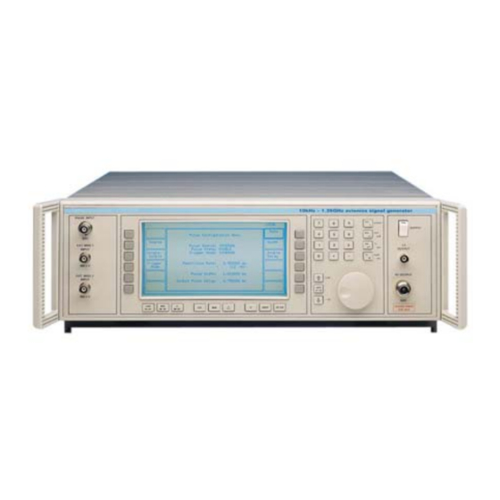
GENERAL INFORMATION INTRODUCTION The NAV-750C Signal Generator covers the frequency range 10 kHz to 1.35 GHz. A dot matrix display with soft key selected screen options allow flexibility of operation and ease of use. The output may be amplitude, phase, or frequency modulated with pulse modulation available as an option. -
Page 26: Modulation
GENERAL INFORMATION A choice of calibration units is available to the operator and provision is made for the simple conversion of units (for example, dBm to μV). Calibration data for the output level is held in memory and may be altered from the front panel or over the interface bus. The output level can be offset by up to ±2 dB by keyboard entry. -
Page 27: Vor Mode
×10 and ÷10 keys. Sweep The sweep capability of the NAV-750C allows comprehensive testing of systems. Four parameters are used to specify sweep; start, stop, number of steps and time per step. These are specified by the user, with upper and lower limits for the parameter values being dependent on the function. -
Page 28: Software Protection
With an SSB phase noise performance of typically -122 dBc/Hz at 470 MHz (20 kHz offset), the NAV-750C can be used for both in-channel and adjacent channel receiver measurements. Harmonically related signals and non-harmonics are better than -30 dBc and -70 dBc respectively. -
Page 29: Performance Data
GENERAL INFORMATION PERFORMANCE DATA CARRIER FREQUENCY Range 10 kHz to 1.35 . By keyboard entry of data. Variation by ⇑/⇓ keys and by rotary Selection control. Indication 11 digits with annunciators. Resolution 0.1 Hz. Accuracy As frequency standard. Phase incrementing The carrier phase can be advanced or retarded in steps of 1.5°... - Page 30 GENERAL INFORMATION SPECTRAL PURITY At RF levels up to +7 dBm : Harmonics Better than -30 dBc for carrier frequencies to 1 GHz; Better than -27 dBc for carrier frequencies above 1 GHz. Sub-harmonics Better than -90 dBc to 1.35 GHz. Non-harmonics Better than -70 dBc to 1.35 GHz for offsets from the carrier frequency of 3 kHz or greater.
- Page 31 GENERAL INFORMATION Difference in Depth DDM can be entered in % or as a modulation index. of Modulation (DDM) Range: 0 to 20% in 0.01% steps. 20 to 99.9% in 0.1% steps, limited by SDM. By keyboard entry of data and variation by ⇑/⇓ keys and rotary Selection: control.
- Page 32 GENERAL INFORMATION VOR MODE 9.96 kHz sub-carrier Range: 0 to 49.9% depth in 0.1% steps. Modulation: Frequency modulated by a 30 Hz tone with 240, 300, 360, 420, 450, 480, 510 and 540 Hz deviation. 30 Hz tone Range: 0 to 49.9% depth in 0.1% steps. Arithmetic sum of 30 Hz tone and sub-carrier AM depth are limited to 99.8%.
- Page 33 GENERAL INFORMATION FREQUENCY MODULATION Deviation Peak deviation from 0 to 1 MHz for carrier frequencies up to 21.09375 MHz; Peak deviation from 0 to 1% of carrier frequency above 21.09375 MHz. By keyboard entry of data. Variation by ⇑/⇓ keys and by rotary Selection control.
- Page 34 GENERAL INFORMATION PHASE MODULATION Deviation 0 to 10 radians. By keyboard entry of data. Variation by ⇑/⇓ keys and by rotary Selection control. Indication 3 digits with annunciators. Better than ±5% of indicated deviation excluding residual phase Accuracy at 1 kHz modulation.
- Page 35 GENERAL INFORMATION MODULATION OSCILLATOR Frequency range 0.1 Hz to 500 kHz. By keyboard entry of data. Variation by ⇑/⇓ keys and by rotary Selection control. Indication 7 digits with annunciators. Resolution 0.1 Hz. Frequency accuracy As frequency standard. Distortion Less than 0.1% THD in sine wave mode at frequencies up to 20 kHz.
- Page 36 GENERAL INFORMATION LF OUTPUT Front panel BNC connector. The output may be configured in either LF Generator Mode to give an output from the internal modulation oscillator or in LF Monitor Mode to give an output from the internal modulation signal paths. By keyboard entry of data.
- Page 37 GENERAL INFORMATION GPIB INTERFACE A GPIB interface is fitted. All functions except the supply switch are remotely programmable. Capabilities Complies with the following subsets as defined in IEEE Std. 488.1. SH1, AH1, T6, L4, SR1, RL1, PP0, DC1, DT1, C0, E2. Conforms with the protection requirements of EEC Council ELECTRO-MAGNETIC Directive 2004/108/EC.
-
Page 38: Accessories
When ordering please quote the full ordering number information. Ordering numbers Supplied accessories AC supply lead (see ‘Power cords’, Chap 2). 46882/293 Operating manual for NAV-750C (this manual). Optional accessories 46881/978 Maintenance manual for NAV-750C. RF connector cable, TM 4969/3, 50 Ω, 1.5 m, BNC. - Page 39 GENERAL INFORMATION 1-16...
- Page 40 GENERAL INFORMATION EC Declaration of Conformity Certificate Ref. No.: DC255 The undersigned, representing: Manufacturer: Aeroflex International Ltd. Address: Longacres House, Six Hills Way, Stevenage, Hertfordshire, UK SG1 2AN Herewith declares that the product: Equipment Description: Signal Generator Model No. NAV-750C Options: —...
- Page 41 Chapter 2 INSTALLATION CONTENTS INITIAL VISUAL INSPECTION ..................2-2 MOUNTING ARRANGEMENTS .................2-2 INSTALLATION REQUIREMENTS................2-2 Ventilation ......................2-2 Class I power cords (3-core) ................2-2 GOODS-IN CHECKS ....................2-5 CONNECTING TO SUPPLY ..................2-5 Voltage selector ....................2-6 Fuses ........................2-6 GENERAL PURPOSE INTERFACE BUS (GPIB)............2-6 GPIB cable connection ..................2-6 GPIB connector contact assignments ..............2-7 IEEE to IEC conversion..................2-7 Interface bus connection ..................2-8...
-
Page 42: Installation
In the event that a molded plug has to be removed from a lead, it must be disposed of immediately. A plug with bare flexible cords is hazardous if engaged in a live socket outlet. Power cords with the following terminations are available from Aeroflex. Please check with your local sales office for availability. - Page 43 INSTALLATION British Country IEC 320 plug type Part number United Kingdom Straight through 23422/001 United Kingdom Right angled 23422/002 EARTH NEUTRAL The UK lead is fitted with an ASTA approved molded plug to LIVE BS 1363. UNITED KINGDOM A replaceable 13 A fuse to BS 1362 is contained within the plug. C3510 This fuse is only designed to protect the lead assembly.
- Page 44 INSTALLATION Français Le câble d'alimentation d'Europe Continentale est muni d'un connecteur mâle à angle droit type CEI83, standard C4 (CEE 7/7), qui peut être utilisé dans une prise femelle à ergot de terre (standard C 3b) ou à clips latéraux (standard C 2b), cette dernière étant communément appelée prise “Schuko”...
-
Page 45: Goods-In Checks
1 Inspect the shipping container and instrument for any signs of damage. If damage is evident, do not plug in, turn on or attempt to operate the instrument. Repackage it and return it to Aeroflex. 2 Verify that your order is complete, including any accessories and options that you may have ordered. -
Page 46: Voltage Selector
Fig. 2-1 AC connector showing voltage selector and fuse holders GENERAL PURPOSE INTERFACE BUS (GPIB) The GPIB interface built into the NAV-750C enables the signal generator to be remotely controlled to form part of an automatic measuring system. GPIB cable connection Connection to other equipment which has a 24-way connector to IEEE Standard 488 is made using the rear panel GPIB socket. -
Page 47: Gpib Connector Contact Assignments
INSTALLATION GPIB connector contact assignments The contact assignments of the GPIB cable connector and the device connector are as shown in Fig. 2-2. Contact Function Contact Function Data I/O 1 DataI/O 5 Data I/O 2 DataI/O 6 Data I/O 3 DataI/O 7 Data I/O 4 DataI/O 8... -
Page 48: Interface Bus Connection
Safety testing and inspection Listed are several important safety precautions which must be observed during installation and operation. Aeroflex assumes no liability for failure of customer to comply with any of the safety precautions outlined in this manual. The following electrical tests and inspection information is provided for guidance purposes and involves the use of voltages and currents that can cause injury. - Page 49 The test voltage should be applied for 5 seconds before taking the measurement. Aeroflex employs reinforced insulation in the construction of its products and hence a minimum pass limit of 7 MΩ should be achieved during this test.
-
Page 50: Battery Replacement
INSTALLATION no hazard to the operator. Aeroflex reserves the right to amend the above information in the course of its continuing commitment to product safety. BATTERY REPLACEMENT The instrument contains a real-time clock which is powered by a lithium battery when the normal power is removed. - Page 51 Chapter 3-1 OPERATION CONTENTS INTRODUCTION ....................3-5 CONVENTIONS ...................... 3-5 FRONT PANEL......................3-5 REAR PANEL ......................3-7 THE MENUS......................3-8 FIRST TIME USE ....................3-9 Switching on ....................3-9 Changing the value of the selected parameter ..........3-10 Enabling or disabling the modulation ............3-10 Using the [⇑...
- Page 52 OPERATION Sweep type ....................3-43 Sweep mode ....................3-45 Sweep parameter entry.................. 3-45 Sweep control....................3-47 UTILITIES........................ 3-49 Adjusting the display ..................3-50 Hardware information................... 3-50 Software information ..................3-50 External trigger ..................... 3-51 Setting the modulation mode ................ 3-51 Setting the GPIB address ................
- Page 53 OPERATION LIST OF FIGURES Fig. 3-1-1 Front panel.................... 3-5 Fig. 3-1-2 Rear panel ..................... 3-7 Fig. 3-1-3 Sig Gen menu - default display............. 3-8 Fig. 3-1-4 Amplitude modulation - menu configuration ........3-10 Fig. 3-1-5 RPP tripped ................... 3-13 Fig.
- Page 54 OPERATION Fig. 3-1-56 Memory recall menu ................3-64 Fig. 3-1-57 Memory stepping menu ................ 3-66 Fig. 3-1-58 Memory store menu ................3-67 Fig. 3-1-59 Frequency hopping menu..............3-69 3-1-4...
-
Page 55: Introduction
The numerical keys are used to set parameters to specific values which can also be varied in steps of any size by using the ⇑/⇓ keys or the rotary control knob. NAV-750C PULSE INPUT enter... - Page 56 OPERATION SUPPLY Switches the AC supply voltage on and off. CARR ON-OFF Enables or disables the carrier frequency. MOD ON-OFF Enables or disables the modulation. LF ON-OFF Switches the low frequency output on and off. UTIL Displays the utilities menu. Displays the memory store/recall menu.
-
Page 57: Rear Panel
OPERATION REAR PANEL The following facilities are available on the rear panel, see Fig. 3-1-2. ------------ ------------ TRIGGER WIDE BAND FREQ STD MARKER RAMP FM IN IN/OUT SWEEP GPIB FUSE 100/120V~ TT1.6AL250V RATING 220/240V~ TT1AL250V POWER SUPPLY 220Vac 100/120/220/240V~ 240Vac 50-400Hz OUTPUT 180VA MAX... -
Page 58: The Menus
OPERATION THE MENUS The NAV-750C instrument is operated by CALling up various displays or menus on the screen. Menus are accessed via both hard and soft keys. Pressing a hard key normally causes the appropriate primary menu to appear on the screen regardless of the current working position within the menu hierarchy. -
Page 59: First Time Use
OPERATION FIRST TIME USE First time users can quickly become familiar with the principles of control and display by carrying out the following exercise, which demonstrates how to set up a typical basic signal having the following parameters: Carrier frequency: 100 MHz. -
Page 60: Changing The Value Of The Selected Parameter
OPERATION Changing the value of the selected parameter If an error is made when keying in, press the soft key again and key in the correct value. If an error message is displayed, it can be canceled by entering a value which is within limits. Using the numerical key pad, enter 100 MHz by pressing keys [1], [0], [0] and the key marked [MHz/mV/ms]. -
Page 61: Using The [⇑ ×10] And [⇓ ÷10] Keys
OPERATION Using the [⇑ ×10] and [⇓ ÷10] keys When a parameter has been selected via the numerical key pad, its value can be ⇓] incremented or decremented either in steps using the [⇑] key and the [ key, or continuously with the control knob. -
Page 62: Detailed Operation
OPERATION DETAILED OPERATION CARRIER FREQUENCY The carrier frequency is selected from the Sig Gen menu by pressing [Carrier Freq.], unless it is already highlighted as in the default display. Enter the required value via the numerical key pad. The value can then be incremented or decremented using the control knob and its associated keys, [KNOB UP-DN], [×10] and [÷10]. -
Page 63: Reverse Power Protection
OPERATION Reverse power protection Accidental application of power to the RF OUTPUT socket trips the reverse power protection circuit (RPP) and a flashing message appears on the display, see Fig. 3-1-5. reset *** REMOVE SIGNAL SOURCE *** C0004 Fig. 3-1-5 RPP tripped Pressing [RPP Reset] resets the RPP and returns the display to the menu in use when the reverse power protection was tripped. -
Page 64: Modulation Mode Selection
OPERATION Composite This mode consists of two modulating channels of the same type of modulation (e.g. FM1 + FM2) with the effective modulation being the sum of the two waveforms. Dual composite This mode is similar to the composite mode of operation but with the two modulating channels being the sum of two sources, e.g. - Page 65 OPERATION Press the [Mod'n Mode] key. This calls up the Modulation Mode Selection Menu shown in Fig. 3-1-7. The five possible modulation modes are shown. Press the required soft key. Fig. 3-1-7 Modulation mode selection menu Press [SIG GEN] to return to the Sig Gen menu where the modulation mode and individual source parameters (where applicable) will be shown.
-
Page 66: Avionics Operation
OPERATION AVIONICS OPERATION Selecting [Avionics Mode] from the Modulation Mode Selection Menu will result in the Avionics Mode Selection menu shown in Fig. 3-1-9 being displayed. Pressing the appropriate soft key will result in the instrument entering the required Avionics mode of operation; pressing [Other Modes] returns the display to the Modulation Mode Selection menu. -
Page 67: Ddm Control
OPERATION The sum of depth of modulation (SDM) is the arithmetic sum of depth of the modulating 90 Hz and 150 Hz tones. Using the [SDM] key the depth can be entered in %. The ILS rate is normally set to 30 Hz and is the ILS waveform repetition rate. Its frequency can be modified using the [ILS Rate] key. - Page 68 OPERATION The [Fly LT/RT] key can be used to set which tone has the greater depth of modulation and the dominant tone is displayed under the DDM set. When 90 Hz is dominant the aircraft is either to the left (localizer) or too high (glideslope). The corresponding action to be taken is displayed as FLY RT and FLY DN.
-
Page 69: Localizer/Glideslope Frequency Conversion
OPERATION Localizer/glideslope frequency conversion International agreements specify that localizer and glideslope frequencies are paired on any ILS installation. The [LOC/GS Freq.] provides a convenient means of switching between the localizer and glideslope frequencies. Provided the carrier frequency is set near to a recognized ILS frequency, pressing [LOC/GS Freq.] will result in the carrier being changed to appropriate paired frequencies. -
Page 70: Communication Channel Testing
OPERATION Communication channel testing ILS systems allow the provision of an emergency voice channel on localizer frequencies. This channel can be tested by selecting the [Ident/Comms] key to produce a display similar to the one shown in Fig. 3-1-14. LOCAL Carrier Carrier : 108.100 0000... -
Page 71: Tone Phase Variability
OPERATION Tone phase variability For normal ILS operation the phase setting between the 90 Hz and 150 Hz tones is automatically set to 0°. The [90/150 Phase] key can be used to adjust the phase relationship of the two tones. Selecting the [90/150 Phase] key produces the display shown in Fig. 3-1-15. Fig. -
Page 72: Marker Beacon Mode
OPERATION Marker beacon mode The marker beacon mode is selected using the [MARKER BEACONS] key on the Avionics Mode Selection Menu shown in Fig. 3-1-9. Selecting maker beacon mode and pressing the [SIG GEN] key produces the display shown in Fig. 3-1-16. Initially the outer beacon is selected by default. -
Page 73: Sub-Carrier Peak Deviation
OPERATION Sub-carrier peak deviation For normal VOR operation the 30 Hz reference signal, which FM modulates the 9960 Hz sub-carrier, has a peak deviation of 480 Hz (Index=16). The [Index ON/OFF] key can be used to adjust the amount of peak deviation applied. Selection the [Index ON/OFF] key produces the display shown in Fig. - Page 74 OPERATION Note... The 9960 Hz sub-carrier and the peak deviation value will change in relation to the VOR rate setting. Example: For a VOR rate of 25 Hz, the sub-carrier will be 8300 Hz and the peak deviation (for an index = 6) will be 400 Hz. The display always reflects the sub-carrier and peak deviation settings for a VOR rate of 30 Hz.
- Page 75 OPERATION Fig. 3-1-20 REF selected The AM depth of the 9960 Hz sub-carrier and the 30 Hz tone can be varied simultaneously by pressing the [Enable Coupling] key which produces the display shown in Fig. 3-1-21. Fig. 3-1-21 VOR made operation with "Coupling" enabled When "coupling"...
-
Page 76: Identity Channel
OPERATION Identity channel VOR signals often carry a morse coded tone to identify the transmitter. This signal can be simulated by selecting the [Ident/Comms] key to produce a display similar to the one shown in Fig. 3-1-22. Fig. 3-1-22 Ident/Comms selected The instrument will generate a VOR signal having equal sub-carrier and 30 Hz tone depths with a 0°... -
Page 77: Adf Mode
OPERATION ADF mode The ADF mode is selected using the [ADF] key on the Avionics Mode Selection Menu shown in Fig. 3-1-9. This menu can be selected from other aviation modes (VOR, ILS, MARKER BEACON, SEL-CAL) using the [Avionics Modes] key. Selecting the ADF mode and pressing the [SIG GEN] key produces the display shown in Fig. -
Page 78: Sel-Cal Mode
OPERATION SEL-CAL mode The SEL-CAL mode can be used to test receivers using AM Selective CALling Tones to the selective CALling format. The mode can be selected from the Avionics Mode Selection Menu shown in Fig 3-1-9. Selecting [SEL-CAL] mode and pressing the [SIG GEN] key produces the display shown in Fig. - Page 79 OPERATION LOCAL Send Tone Sequential Calling Tones Utility Tones Sequence Current Standard : SEL-CAL Mode Mode AM1 - SINGLE SHOT Control GAJB - - - - - - - - - - - - Select Tone Seq. : Standard Selective Calling Standard Tone Duration Tone Duration...
-
Page 80: Analog Modulation Mode
OPERATION ANALOG MODULATION MODE Selecting the modulation The type of modulation required, AM, FM, ΦM, wideband and optional pulse modulation can be selected by soft keys at the Sig Gen menu. Five modulation modes are available, see 'Modulation mode selection' above. Modulation ON/OFF [MOD ON-OFF] switches all modulation ON or OFF and the condition is indicated in the center of the main display, e.g.:... -
Page 81: Selecting Wideband Frequency Modulation
OPERATION Selecting wideband frequency modulation At the Sig Gen menu, press [Wideband FM]. The [Wideband FM] box will be highlighted. The value can be changed via the key pad and frequency terminator key. To preserve the widest bandwidth, the control of the wideband FM is carried out in a series of fixed steps and the signal generator automatically displays the calculated fixed step which is closest to the keyed in value. -
Page 82: Source Selection - Internal
OPERATION Source selection - internal The modulation source may be selected by pressing [Select Source]. Sources may be internal or external. If the currently selected source is internal, the Internal Source Selection Menu is displayed, giving a choice of six frequencies, F1-F6, see Fig. 3-1-27. The frequency assigned to the highlighted F number may be changed by the numerical key pad and terminated with [Hz], [kHz], [MHz] or [GHz]. - Page 83 OPERATION LF phase When an internal source has been selected, its phase relative to the second modulation oscillator (if fitted) can be changed by pressing [Mod. Src Phase] and entering the required value. Where two internal modulation frequencies are active, the starting phase difference between the two signals can be set up and the phase angle is referred to the currently selected oscillator.
-
Page 84: Source Selection - External
OPERATION Source selection - external An external source may be selected by pressing [Select External]. The External Source Selection Menu is then displayed on the screen (This menu is displayed immediately when pressing [Select Source] if the currently selected source is external). This menu allows the choice of two input sockets EXT MOD 1 INPUT and EXT MOD 2 INPUT and AC, ALC, or DC coupling by pressing the appropriate soft key. -
Page 85: Modulation Alc
OPERATION MODULATION ALC The automatic leveling control (ALC) is used in conjunction with an external source and can be disabled when not required. To enable the ALC, proceed as follows: At the Sig Gen menu, press [Select Source]. The display will show the Internal or External Source Selection Menu (Fig. -
Page 86: Signaling
OPERATION SIGNALING CTCSS A CTCSS tone is any one of 32 standard sub-audible tones ranging from 67 Hz to 250.3 Hz and would generally be used in conjunction with an audible modulation signal in a composite modulation mode. The procedure for initiating these tones is as follows: Tone selection At the Sig Gen menu, press [Select Source]. -
Page 87: Sequential Calling Tones
OPERATION Note... Selecting [CTCSS1], [CTCSS2], [USER] or [TEMP] from the Tone Standard Selection Menu causes the pictogram in the Continuous Tone Selection Menu and the Internal Source Selection Menu to change e.g. ctc1. The pictogram is repeated in the modulation section of the Sig Gen menu. - Page 88 Fig. 3-1-32 Sequential CALling tones utility menu (DTMF mode) DTMF signaling capability is also provided with the NAV-750C. If this standard is selected then the main menu accessed after pressing the [CALling Tones] soft key at Utilities Selection Menu 1 will be as shown in Fig.
- Page 89 OPERATION [Tone Duration] The default duration of 70 ms for each tone in the sequence can be changed by pressing this key, entering the required duration value and pressing [ms]. [Tone Gap] The default gap duration of 70 ms between each tone in the sequence can be changed by pressing this key, entering the required gap length and pressing [ms].
- Page 90 OPERATION Selecting alternative tone standards The [Select Standard] key causes the Tone Standard Selection Menu to be displayed, see Fig. 3-1-34. LOCAL CCIR Tone Standard Selection Menu EURO Current Standard: CCIR Tone 0: 1.9810 kHz Tone 8: 1.7470 kHz DZVEI NATEL Tone 1: 1.1240 kHz Tone 9: 1.8600 kHz...
- Page 91 OPERATION Note that when using the DTMF tone signaling capability no editing facility is provided. Changes to the default settings are made directly on the CALling Tones Utility Menu. LOCAL CCIR Tone Edit Sequencial Tones Standard to TEMP Number Tone Tone Number: Freq.
-
Page 92: Displaying Shifts
OPERATION (using Δ) INCREMENTING Displaying shifts Press the [Δ] hard key. The total shift menu is displayed as shown in Fig. 3-1-36. This menu displays the difference between the current value and the keyed-in value. Parameters can be incremented or decremented by using the [⇑] or [⇓] key or the control knob, see 'Using the control knob' on Page 3-1-11. -
Page 93: Sweep
OPERATION SWEEP The sweep capability allows the comprehensive testing of systems, as measurements at single points will not necessarily give an overall indication of the performance. The sweep function is specified by the following parameters: • Start value • Stop value •... - Page 94 OPERATION LOCAL LF Freq Carrier Sweep Sweep Sweep Type Menu RF Level LF Level Sweep Sweep Current Sweep Type: RF LEVEL Int. F4 Sweep Sweep EXIT C0052 Fig. 3-1-38 Sweep type menu The instrument must be in the LF generator mode before an LF frequency sweep and LF level sweep can be initiated.
-
Page 95: Sweep Mode
OPERATION Sweep mode At the sweep parameters menu, press [Sweep Mode]. The Sweep Trigger Mode Menu is displayed, see Fig. 3-1-39. LOCAL Internal Single Sweep Trigger Mode Menu Internal Cont. Current Sweep Mode: INTERNAL SINGLE External Trigger EXIT C0017 Fig. 3-1-39 Sweep trigger mode menu Select the sweep mode, [Internal Single], [Internal Cont.], or [External Trigger]. - Page 96 OPERATION Number of steps Select [Number of Steps]. Enter the number of steps via the numerical key pad and the [GHz/V/enter] terminator key. Note... If an inappropriate number of steps is selected, the instrument will automatically choose a more reasonable value. The number of steps available depends on the operating mode and the maximum values are: for carrier frequency with FM, ΦM or Wideband FM enabled for carrier frequency without FM, ΦM or Wideband FM enabled.
-
Page 97: Sweep Control
OPERATION Sweep control Starting the sweep From the sweep parameters menu, press [Start Sweep]. The single sweep status line display changes from WAITING FOR TRIGGER to SWEEPING and a solid bar increments to show the sweep progression, see Fig. 3-1-41. LOCAL Stop Level Start:... - Page 98 OPERATION LOCAL Stop Level Start: -144.0 Sweep Reset Level Stop: +13.0 Sweep Number of: 1000 ----- Transfer Steps Step Time: Sweep Status: PAUSED AT +6.4 dBm Sweep Mode: INTERNAL SINGLE Sweep Type: RF LEVEL C1901 Fig. 3-1-42 Sweep stopped LOCAL Carrier Carrier : 626.407 6800...
-
Page 99: Utilities
OPERATION UTILITIES The utilities options are accessible from two primary menus, Utilities Selection Menu 1 and Utilities Selection Menu 2. When a selection is made from either of these menus and [UTIL] is subsequently pressed, the primary menu is re-displayed. However, if instead a selection is made and then one of the other hard keys e.g. -
Page 100: Adjusting The Display
OPERATION Adjusting the display To adjust the display, press [Display Adjust]. The Display Adjust menu is displayed on the screen, see Fig. 3-1-45. The backlight, which is on when the instrument is switched ON, can be toggled ON or OFF using the [Display ON/OFF] key, and when ON can be varied in brightness by [Dim], [Medium 1], [Medium 2] and [Bright]. -
Page 101: External Trigger
OPERATION External trigger The external trigger facility allows the rear panel TRIGGER input to be set up so as to initiate a defined change in the generator setting. To define the function press [External Trigger]. The display changes to show the External Trigger Selection Menu which has the following options: [Sweep Start] Starts the external sweep. -
Page 102: Selection Of Frequency Standard
OPERATION Selection of frequency standard Pressing [Int/Ext Standard] changes the menu to display the Frequency Standard Selection Menu which controls the internal/external frequency standard facilities. The signal generator can be set to operate from an external standard or from the internal standard with or without the standard being provided on the rear panel FREQ STD IN/OUT connector. -
Page 103: Calibration
OPERATION Calibration Pressing [Cal. Value] brings the Calibration Utilities Menu to the display, see Fig. 3-1-47. This menu shows when the last complete check was made and when the next calibration check is due. It also shows the date on which the individual items were adjusted. It is possible to inspect the calibration value of these items but calibration cannot be carried out unless the protection facility is unlocked at Level 2. -
Page 104: Locking And Unlocking
OPERATION Locking and unlocking Press [Lock & Unlock]. When Level 1 and Level 2 are both locked, the menu displays three soft keys: Unlock Level 1 Unlock Level 2 Serial No. Set Press [Unlock Level 1] and the message Enter 4 Digit Password: will appear on the display. -
Page 105: Setting Time And Date
Display blanking To prevent sensitive data from being displayed, the NAV-750C Signal Generators include a display blanking facility. This allows various parts of the display to be replaced by a series of dashes so that values entered by the user or recalled from the memory will not be visible. The instrument must be unlocked to Level 2 to enable or disable this facility. -
Page 106: Rf Level Units
OPERATION RF level units RF output level units can be altered using the [Level Units] key. The level units may be entered as an EMF or PD, and the logarithmic units can be referred to volts (dBV), millivolts (dBmV), microvolts (dBμV) or to 1 milliwatt into 50 Ω(dBm). Select the units by pressing [Level Units] which displays the RF Level Units Selection Menu shown in Fig. -
Page 107: Lf Level Units
OPERATION LF level units LF level logarithmic units may be referenced to 1 volt EMF (dBV EMF), 1 millivolt EMF (dBmV EMF) or 1 milliwatt into 600 Ω(dBm). Linear units are always set EMF values. Select the units by pressing the [LF Level Units] soft key on the RF Level Units Selection Menu which calls up the LF Level Units Selection Menu shown in Fig. -
Page 108: Rf Level Utility
OPERATION RF level utility Selecting [RF Level Utility] from the Utilities Selection Menu 2 displays the RF Level Utility Menu shown in Fig. 3-1-50. LOCAL RF Level Utility Menu Extended Extended Hysteresis : ENABLED Offsets CW Burst RF Level CW Burst Suppression : ENABLED Control Limit... - Page 109 OPERATION +13 dBm +6 dBm 0 dBm -24 dBm -18 dBm -12 dBm -6 dBm 0 dBm +13 dBm 0 dB Requested output level 6 dB 12 dB 18 dB C0956 24 dB Fig. 3-1-51 Normal signal generator level control operation +12 dBm +6 dBm 0 dBm...
- Page 110 OPERATION RF offset With the instrument unlocked to Level 1, see 'Locking and unlocking' above, pressing [Offsets] produces the layout for the soft keys shown in Fig. 3-1-53. LOCAL Carrier Save Carrier : 1 050.000 000 Freq. Offset Feq. Enable/ Offset -102.0 Disable...
- Page 111 OPERATION RF level limit With the instrument unlocked to level 1, see 'Locking and unlocking' above, pressing the [RF Level Limit] key causes the RF Level Limit Menu shown in Fig. 3-1-54 to be displayed. LOCAL Save RF level RF Level Limit Menu Setting Limit Enable/...
-
Page 112: Low Frequency Operation
OPERATION LOW FREQUENCY OPERATION The instrument has two modes of LF operation. The LF output can be used either as a modulation signal monitor or as an independent low frequency generator. Pressing [LF] displays either the LF Monitor Menu or the LF Generator Menu, depending on which mode was last selected. -
Page 113: Use As An Independent Lf Generator
OPERATION Use as an independent LF generator To use the instrument as an independent LF generator, select [LF Gen.] at the LF Monitor Menu. The LF Generator Menu appears on the display as shown in Fig. 3-1-55. LOCAL Sine Freq. Wave LF Generator Menu Triangle... -
Page 114: Memory
OPERATION MEMORY Memory recall Pressing the [MEM] hard key after switch on, causes the Memory Recall Menu, Fig. 3-1-56, to be displayed. There are four types of recall, full, partial, carrier frequency and sweep. Provision is made for an option not to recall the carrier frequency for full and partial stores. - Page 115 OPERATION Carrier recall The carrier frequency store has 100 locations (numbered 0 to 99) which may be recalled when required. Sweep recall The sweep store has 20 locations (numbered 0 to 19) containing complete sets of sweep parameters which may be recalled when required. Note...
-
Page 116: Memory Stepping Facility
OPERATION Memory stepping facility The [Sig Gen] key has a toggle action in that pressing the key a second time displays the Memory Stepping menu shown in Fig. 3-1-57. This facility enables the memory to be stepped up and down from a start location (selected using the Memory Recall Menu), whilst displaying the settings for that memory. -
Page 117: Memory Store
OPERATION Memory store Pressing the [Memory Store] soft key on the Memory Recall Menu causes the Memory Store Menu, Fig. 3-1-58, to be displayed. There are four types of store, full, partial, carrier frequency and sweep. To prevent the accidental overwriting of memory contents, a store protection facility is provided. - Page 118 OPERATION LF generator frequency step size LF generator level setting LF generator level step size LF monitor settings Display blanking settings Partial store This is a less comprehensive store of only those parameters which currently affect the RF output; carrier frequency, RF level, modulations in use (without increments), ON/OFF and source information and the two modulation oscillator frequencies in use.
-
Page 119: Frequency Hopping
OPERATION Frequency hopping Carrier frequency hopping is a GPIB operation where the instrument can be instructed to hop between any of the frequencies contained in the carrier frequency stores and a sequence of up to 1024 hops may be entered. The time interval between hops can also be entered . Before executing a carrier hopping sequence, the frequencies must be loaded into the carrier frequency stores (0 - 99). - Page 120 OPERATION Note:... If any of the carrier frequency stores have become corrupt and so result in a checksum error, the following message will appear in the center of the screen - CARRIER STORE < x > CORRUPTED. RE - ENTER FREQUENCY. where x is the corrupted store number.
- Page 121 OPERATION Like other sweep settings the frequency hopping mode can be set to - single sweep (internal trigger), continuous sweep (internal trigger) or external sweep (external trigger) by using the following commands - SWEEP:MODE SNGL SWEEP:MODE CONT SWEEP:MODE EXT For externally triggered operation the trigger facility can be used in the same manner as another sweep function.
-
Page 122: Error Handling
OPERATION ERROR HANDLING Errors may be divided into three groups - foreground errors generally caused by a user, background errors which represent a condition of the instrument and GPIB errors which occur only when the unit is being controlled by a GPIB controller. Foreground errors Attempts to set the instrument to a parameter value outside its known range result in the generation of an error message. -
Page 123: Error Messages
OPERATION ERROR MESSAGES TABLE 3-1-2 BACKGROUND ERRORS Error Error Descriptive text Descriptive text Type Type RPP Tripped VCXO Out of Lock Fractional N Out of Lock Ext1 Too Low Int. Standard Failure Ext1 Too High Ext. Standard Failure Ext2 Too Low Incorrect Ext. -
Page 124: Table 3-1-3 Foreground Errors
OPERATION TABLE 3-1-3 FOREGROUND ERRORS Error Error Descriptive text Descriptive text Type Type Recall Checksum Carrier Outside Limits Incorrect Setup RF Level Outside Limits Invalid Memory Number Mod Rate Outside Limits MODULATION NOT ENABLED LF Freq. Outside Limits Out of Range LF Level Outside Limits AM Outside Limits RF Level Step Too Big... -
Page 125: Table 3-1-4 Gpib Errors
OPERATION TABLE 3-1-4 GPIB ERRORS Error Error Descriptive text Descriptive text Type Type Data Expected Mnemonic Fault Illegal Data Block Definition Terminator Expected Block Size GET Error Numeric Syntax EOM Error Illegal Modulation Mode Unterminated No Such Monitor Mode Interrupted Cannot Monitor Deadlock Instrument Mode Wrong... - Page 126 Chapter 3-2 GPIB OPERATION CONTENTS INTRODUCTION ....................3-2-2 INTRODUCTION ....................3-2-2 GPIB FUNCTIONS ....................3-2-2 DEVICE LISTENING ELEMENTS ................ 3-2-3 DEVICE TALKING ELEMENTS ................3-2-3 PROGRAMMING ....................3-2-4 Program messages..................3-2-4 Compound headers..................3-2-4 Program data ....................3-2-5 Message exchange protocol ................3-2-5 Remote/local operation .................
-
Page 127: Gpib Operation
GPIB OPERATION INTRODUCTION The NAV-750C signal generator can be operated remotely from a personal computer fitted with a GPIB interface card or a dedicated GPIB controller. All functions can be controlled by coded messages sent over the interface bus via the 24 way socket on the rear panel of the instrument. -
Page 128: Device Listening Elements
GPIB OPERATION DEVICE LISTENING ELEMENTS The following is a list of the device listening elements (as defined in the IEEE 488.2 standard) which are used in the NAV-750C signal generator: <PROGRAM MESSAGE> <PROGRAM MESSAGE TERMINATOR> <PROGRAM MESSAGE UNIT> <PROGRAM MESSAGE UNIT SEPARATOR>... -
Page 129: Programming
NAV-750C in the same way). Compound headers The NAV-750C implements compound headers which allow a complex set of commands to be built up from a small set of basic elements in a 'tree and branch' structure. The elements of a compound header are separated by a colon (:). -
Page 130: Program Data
DEADLOCK (error 118) can only occur if the input and output buffers are both filled by the controller having sent an extra long Message containing several query message units. The NAV-750C have input buffer stores of 256 characters and an output buffer of two response message units. -
Page 131: Common Commands And Queries (Ieee 488.2)
Common command and query mnemonics are preceded by an asterisk (*) to distinguish them from device dependent data such as instrument programming strings. The following common commands and queries are implemented in the NAV-750C: Mnemonic Name and Description *IDN? Identification Query. - Page 132 GPIB OPERATION *SRE <nrf> Service Request Enable Command. Sets the Service Request Enable Register. *SRE? Service Request Enable Query. Returns the value of the Service Request Enable Register as nr1. *ESR? Standard Event Status Register Query. Returns the value of the Status Event Status Register as nr1.
-
Page 133: Device Dependent Commands
The following list describes the features of the device dependent mnemonics for the NAV-750C signal generator together with simple examples of their use within each major section (carrier frequency, RF level, etc.) the root mnemonic is listed first followed by the lower level mnemonics. - Page 134 GPIB OPERATION TABLE 3-2-1 INSTRUMENT DEFAULT SETTINGS (continued) Modulations: 0 Hz, Int F4, ON 0 Hz, Ext 1 ALC, ON ΦM1 0 rad, Int F4, ON ΦM2 0 rad, Ext 1 ALC, ON 0%, Int F4, ON 0%, Ext 2 ALC, ON WBFM : (Minimum setting), AC coupled, ON ΔFM 1 kHz, Δ...
-
Page 135: Instrument Mode
GPIB OPERATION INSTRUMENT MODE IMODE Select instrument mode Character Program Data (either NORMAL for signal generator Data type : operation or SWEEPER for swept operation) None Allowed suffices : None Default suffix : Example: IMODE NORMAL CARRIER FREQUENCY CFRQ Set Carrier Frequency (short form) Set Carrier Frequency :VALUE Set Carrier Frequency step... -
Page 136: Rf Level
GPIB OPERATION RF LEVEL RFLV Set RF output level (short form) Set RF output level :VALUE Data type : Decimal Numeric Program Data Any one of: DBM, DBV, DBMV, DBUV, V, MV or UV Allowed suffices : dBm unless changed by UNITS command Default suffix : :INC Set RF level step (dB) - Page 137 GPIB OPERATION :OFFS [not used alone] Set Offset of current band :VALUE Data type : Decimal Numeric Program Data DB only Allowed suffices : Default suffix : Turn ON offset of current band Turn OFF offset of current band :OFF Enable Offsets :ENABLE Disable Offsets...
- Page 138 GPIB OPERATION RFLV [not used alone] :HYST Enable Extended Hysteresis mode :ENABLE Disable Extended Hysteresis mode :DISABLE Data type : None None Allowed suffices : None Default suffix : Responds with status as follows: RFLV:HYST? :RFLV:HYST:ENABLE :RFLV:HYST:DISABLE RFLV Set RF output level limit (short form) :LIMIT Set RF output level limit :VALUE...
-
Page 139: Avionics Modes
GPIB OPERATION AVIONICS MODES Set avionics mode MODE (in addition to existing modulation mode commands) Character Program Data (valid combinations of SDM, DDM, Data type : VOR, BEAR or AM2, see Table below) None Allowed suffices : None Default suffix : Examples: MODE SDM,DDM (select ILS mode with DDM) MODE SDM,AM2 (select ILS mode with AM2) -
Page 140: Ils (Instrument Landing System) Mode
GPIB OPERATION ILS (Instrument Landing System) mode Set Sum of Depth of Modulation (short form) Set SDM Depth :DEPTH Set SDM step size :INC Decimal Numeric Program Data Data type : Allowed suffices : Default suffix : Go UP one step Go DOWN one step Return to original setting :RETN... - Page 141 GPIB OPERATION Go UP one step Go DOWN one step Return to original setting :RETN Transfer current value to be the new setting :XFER None Data type : None Allowed suffices : None Default suffix : Examples: DDM90:DEPTH 40PCT;INC 0.1;DN;DN DDM150:DEPTH 0.1554;INC 0.0002;UP;UP;UP Prepares messages containing information on DDM in the DDM?
-
Page 142: Marker Beacon Mode
GPIB OPERATION Example: ILSF:VALUE 30 Hz;INC 0.1;DN;DN;DN Prepares messages containing information on ILS Frequency in ILSF? the following format: :ILSF:VALUE <nr2>;INC <nr2> Example: :ILSF:VALUE 30.0;INC 0.5 Marker beacon mode There are no additional commands for marker beacon testing, the required setting is obtained by using the appropriate standard commands. -
Page 143: Vor (Vhf Omnidirectional Radio Range) Mode
GPIB OPERATION VOR (VHF Omnidirectional Radio Range) mode Set SUB Subcarrier Signal (9960 Hz) Depth (short form) VOR or SUB Set SUB Depth :DEPTH Set SUB step size :INC Decimal Numeric Program Data Data type : Allowed suffices : Default suffix : Go UP one step Go DOWN one step Return to original setting... - Page 144 GPIB OPERATION Prepares messages containing information on REF in the REF? following format: :REF:DEPTH <nr2>;INC <nr2> Example : :REF:DEPTH 30.0;INC 0.5 Set VOR Bearing To Beacon (short form) BEARTO Set VOR Bearing To Beacon :VALUE Set VOR Bearing From Beacon (short form) BEARFR Set VOR Bearing From Beacon :VALUE...
-
Page 145: Adf (Automatic Direction Finder) Mode
GPIB OPERATION Prepares messages containing information on VOR Frequency VORF? in the following format: :VORF:VALUE <nr2>;INC <nr2> :VORF:VALUE 30.0;INC 0.5 Example : ADF (Automatic Direction Finder) mode There are no additional commands for ADF testing, the required setting is obtained by using the appropriate standard commands. -
Page 146: Modulation Mode
GPIB OPERATION MODULATION MODE MODE Set modulation mode Character Program Data (valid combinations of AM, AM1, Data type : AM2, FM, FM1, FM2, PM, PM1, PM2, WBFM or PULSE, see Table below) None Allowed suffices : None Default suffix : Examples: MODE AM,FM MODE FM1,FM2... -
Page 147: Modulation Control
GPIB OPERATION MODULATION CONTROL [not used alone] Turn modulation globally ON Turn modulation globally OFF :OFF Examples: MOD:ON MOD:OFF MOD? Prepares message containing information on Modulation Control in the following format: :MOD:<status> where: <status> is a program mnemonic indicating whether the Modulation is globally ON or OFF. -
Page 148: Frequency Modulation
GPIB OPERATION FREQUENCY MODULATION FM or FM1 or FM2 Set FM deviation (short form) Set FM deviation :DEVN Set FM step size :INC Data type : Decimal Numeric Program Data Any one of: GHZ, MHZ, KHZ or HZ Allowed suffices : Default suffix : :<src>... -
Page 149: Phase Modulation
GPIB OPERATION PHASE MODULATION PM or PM1 or PM2 Set Phase deviation (short form) Set Phase deviation :DEVN Set Phase Modulation step size :INC Data type : Decimal Numeric Program Data RAD or RADS Allowed suffices : Default suffix : :<src>... -
Page 150: Amplitude Modulation
GPIB OPERATION AMPLITUDE MODULATION AM or AM1 or AM2 Set AM Depth (short form) Set AM Depth :DEPTH Set AM step size :INC Data type : Decimal Numeric Program Data Allowed suffices : Default suffix : :<src> Select modulation source where <src> is any one of: INTF1, INTF2, INTF3, INTF4, INTF5, INTF6, EXT1DC, EXT1AC, EXT1ALC, EXT2DC, EXT2AC or EXT2ALC Turn AM ON (local) -
Page 151: Wideband Fm
GPIB OPERATION WIDEBAND FM WBFM Set WBFM deviation (short form) Set WBFM deviation :DEVN Data type : Decimal Numeric Program Data Any one of: GHZ, MHZ, KHZ or HZ Allowed suffices : Default suffix : Turn WBFM ON (local) Turn WBFM OFF (local) :OFF Select AC coupling Select DC coupling... -
Page 152: Pulse Modulation
GPIB OPERATION PULSE MODULATION PULSE [not used alone] Turn Pulse modulation ON Turn Pulse modulation OFF and select Low Intermodulation :OFF Enable CW burst suppression mode :CAL:ENABLE Disable CW burst suppression mode :DISABLE Data type : None None Allowed suffices : None Default suffix : Examples:... -
Page 153: Modulation Frequency
GPIB OPERATION MODULATION FREQUENCY INTF1 or INTF2 or INTF3 or Set modulation oscillator frequency (short form) INTF4 or INTF5 or INTF6 Set modulation oscillator frequency :FREQ Set modulation oscillator frequency step size :INC Data type : Decimal Numeric Program Data Any one of: GHZ, MHZ, KHZ or HZ Allowed suffices : Default suffix :... -
Page 154: Ctcss Tones Edit
GPIB OPERATION CTCSS TONES EDIT CTONES [not used alone] [not used alone] :EDIT Select tone number 0-15 :TNUM Data type : Decimal Numeric Program Data None Allowed suffices : None Default suffix : :TFRQ Set tone frequency Data type : Decimal Numeric Program Data Any one of: GHZ, MHZ, KHZ or HZ Allowed suffices :... -
Page 155: Sequential Tones
GPIB OPERATION SEQUENTIAL TONES SEQT [not used alone] Set Tone sequence :SEQ Data type : String Program Data consisting of up to 16 characters from 0 to 9 and A to F between string delimiters (eg. "123C5" or '123C5'). For DTMF E and F are not allowed and are replaced by * and #. - Page 156 GPIB OPERATION :RPTT Select Repeat Tone Data type : String Program Data (any one of 0 to 9 or A to F between strings delimiters (eg. "E" or 'E'). None Allowed suffices : None Default suffix : :TDUR Set DTMF Tone duration Set DTMF inter-element gap :TGAP Data type :...
- Page 157 GPIB OPERATION SEQT? Prepares message containing information on the signalling sequence and duration settings in the following format: :SEQT:SEQ <toneseq>;DUR <durseq> where: <toneseq> is string program data defining the tone sequence and <durseq> is string program data defining the duration sequence. Examples: :SEQT:SEQ "12245B7";DUR "----E--"...
-
Page 158: Lf Control
GPIB OPERATION LF CONTROL [not used alone] Turn LF output ON Turn LF output OFF :OFF Select LF Generator :GEN Data type : None None Allowed suffices : None Default suffix : :MON Select source monitor mode Data type : Character Program Data (any one of: AM1S, AM2S, AMD, ANG1S, ANG2S, ANGD or OFF, where AM represents Amplitude Modulation, ANG represents Angular Modulation,... -
Page 159: Lf Generator Frequency
GPIB OPERATION LF GENERATOR FREQUENCY LFGF Set LF Generator frequency (short form) Set LF Generator frequency :VALUE Set LF Generator frequency step :INC Data type : Decimal Numeric Program Data Any one of: GHZ, MHZ, KHZ or HZ Allowed suffices : Default suffix : Go UP one step Go DOWN one step... -
Page 160: Lf Generator Level
GPIB OPERATION LF GENERATOR LEVEL LFGL Set LF Generator level (short form) Set LF Generator level :VALUE Data type : Decimal Numeric Program Data V, MV, UV, DBMV Allowed suffices : Default suffix : :INC Set LF Generator level step Data type : Decimal Numeric Program Data Allowed suffices :... -
Page 161: Memory - Store
GPIB OPERATION MEMORY - STORE [not used alone] Full Store 0-49 :FULL Partial Store 0-49 :PART Carrier Freq Store 0-99 :CFRQ Sequential Tones Store 0-19 :SEQT Sweep Store 0-19 :SWEEP Data type : Decimal Numeric Program Data None Allowed suffices : None Default suffix : Examples:... -
Page 162: Sweep Operation
GPIB OPERATION SWEEP OPERATION IMODE Select Instrument Mode Data type : Character Program Data (either NORMAL for signal generator operation or SWEEPER for swept operation ) None Allowed suffices : None Default suffix : Example: IMODE SWEEPER SWEEP [not used alone] :MKRON Enable Sweep Markers Disable sweep Markers... - Page 163 GPIB OPERATION SWEEP? (continued) :STEP Select number of steps in the sweep. Data type : Decimal Numeric Program Data None Allowed suffices : None Default suffix : :TIME Select time per sweep step Data type : Decimal Numeric Program Data Allowed suffices : Default suffix : :MKRNUM...
- Page 164 GPIB OPERATION SWEEP? (continued) :RFLV? Prepares message containing information on RF Level Sweep settings in the following format: :SWEEP:START <nr2>;STOP <nr2>;STEP <nr1>;TIME <nr1>; MKRNUM <nr1>;<status>;VALUE <nr2> where: <status> is a program mnemonic indicating whether the selected Marker is ON or OFF. Sample response: :SWEEP:START -107.0;STOP -27.0;STEP 80;TIME 50;...
-
Page 165: Sweep Mode/Type
GPIB OPERATION SWEEP MODE/TYPE SWEEP [not used alone] Select Mode of operation for Sweep generator (single shot, :MODE continuous or externally triggered) Data type : Character Program Data (any one of SNGL, CONT or EXT) None Allowed suffices : None Default suffix : :TYPE Select Type of Sweep (Carrier Frequency, RF Level, LF... - Page 166 GPIB OPERATION FREQUENCY HOPPING HOPSEQ Enter frequency hopping sequence Decimal Numeric Program data (can be multiple) Data type : None Allowed suffices : None Default suffix : Examples: HOPSEQ 56, 72, 0, 4, 99, 72 HOPSEQ 255, 0, 4, 17, 23, 64, 72 HOPSEQ? Returns a value 0-1024 indicating the number of steps in the Frequency Hopping Sequence.
-
Page 167: Miscellaneous Commands
GPIB OPERATION MISCELLANEOUS COMMANDS IMODE Select Instrument Mode Data type : Character Program Data (either NORMAL for signal generator operation or SWEEPER for swept operation ) None Allowed suffices : None Default suffix : RPPR Reset reverse power protection trip Data type : None None... - Page 168 GPIB OPERATION TIME? Prepares message containing information on current real time clock time setting in the format: <HH:MM> where: <HH:MM> is string program data representing the time in hours and minutes using the 24 hour clock notation. Example: "17:55" DATE? Prepares message containing information on current real time clock date setting in the format: <YYYY-MM-DD>...
- Page 169 GPIB OPERATION EXTTRG Set External Trigger Function (action on Low signal being applied to External Trigger Socket). Data type : Character Program Data (any one of: SEQT, FLSWP, SSSWP, MEMUP, MEMDN or VOID) None Allowed suffices : None Default suffix : Examples: DEVTRG SEQT EXTTRG MEMUP...
-
Page 170: The Status Byte
Bit 5 is the Event Summary Bit (<esb>), the Summary Message from the Standard Event Status Register. In NAV-750C, bit 7 is a Queue Summary for the Error Queue. Bits 1, 2, and 3 are Status summaries for the Instrument Status, Coupling Status and Hardware Status Registers. Bit 0 is unused. -
Page 171: Status Data Structure - Register Model
Event Register. Either positive-going, negative-going or both transitions can set bits in an Event Register. But in the NAV-750C the Transition Filters are pre-set as either Positive or Negative, as described in the following pages. - Page 172 GPIB OPERATION The bits in an Event Register are "latched". Once set they remain set, regardless of subsequent changes in the associated condition bit until the Event Register is cleared by being read or by the *CLS common command. Once cleared, an Event Register bit will only be set again if the appropriate change in the Condition bit occurs.
-
Page 173: Standard Event Registers
GPIB OPERATION STANDARD EVENT REGISTERS This Register is defined by IEEE 488.2 and each bit has the meaning shown below:- Condition Register Register <pon> <urq> <cme> <exe> <dde> <qye> <rqc> <opc> Read/Write Commands Transition Filter # <pon> <urq> <cme> <exe> <dde>... -
Page 174: Hardware Event Registers
GPIB OPERATION HARDWARE EVENT REGISTERS This is a device dependent Register and the bits have meanings as shown in the list at the bottom of the page. Condition Register HCR? Transition Filter # Register Read/Write Commands Status Register HSR? & &... -
Page 175: Coupling Event Registers
GPIB OPERATION COUPLING EVENT REGISTERS This is a device dependent Register and the bits have meanings as shown in the list at the bottom of the page. Condition Register CCR? Transition Filter # Register Read/Write Commands Status Register CSR? & &... -
Page 176: Instrument Event Registers
GPIB OPERATION INSTRUMENT EVENT REGISTERS This is a device dependant Register and the bits have meanings as shown in the list at the bottom of the page. Condition Register SCR? Transition Filter # Register Read/Write Commands Status Register SSR? & &... -
Page 177: Queue Flag Details
GPIB OPERATION QUEUE FLAG DETAILS Input from all Error Conditions Status Byte & Enable Register non-zero From Standard Event Registers Error Queue Response Message Response ERROR? Device Dependant Errors Output Queue <erb> <mss> <mav> <hsb> <csb> <ssb> <esb> Status Byte Register Data from Output Queue C0075 The <mav>... -
Page 178: Status Byte When Read By *Stb
GPIB OPERATION STATUS BYTE WHEN READ BY *STB? Status Byte Register Register Read Command <mav> <hsb> <csb> <ssb> <erb> <mss> <esb> *STB? & & & & & & & *SRE *SRE? Register Service Request Enable Register# C0073 Read/Write Commands # Bit 6 in this register ignores data sent by *SRE and always returns 0 in response to *SRE? <rqs>, <esb>... -
Page 179: Status Byte When Read By Serial Poll
GPIB OPERATION STATUS BYTE WHEN READ BY SERIAL POLL Status Byte Register <mav> <hsb> <csb> <ssb> <erb> <mss> <esb> Service Request Generation *SRE *SRE? Register Service Request Enable Register# C0074 Read/Write Commands # Bit 6 in this register ignores data sent by *SRE and always returns 0 in response to *SRE? <erb>... -
Page 180: Summary Of Status Reporting Commands And Queries
GPIB OPERATION SUMMARY OF STATUS REPORTING COMMANDS AND QUERIES *CLS Clears Status Registers and the Error Queue *ESE<nrf> Writes to Standard Event Enable Register *ESE? Reads from Standard Event Enable Register *ESR? Reads from Standard Event Status Register *SRE<nrf> Writes to Service Request Enable Register *SRE? Reads from Service Request Enable Register *STB? - Page 181 CONTROL The NAV-750C is a menu driven instrument. Main menus are displayed by the use of hard keys, and parameters are changed by means of soft keys which change as the menu changes. Internal control of the instrument is achieved by a microprocessor which receives data from the various controls and sends instructions via an internal 8-bit data bus to the signal processing circuits.
- Page 182 BRIEF TECHNICAL DESCRIPTION Fig. 4-1-1 Block schematic diagram 4-1-2...
- Page 183 Chapter 5-1 ACCEPTANCE TESTING CONTENTS INTRODUCTION ....................5-1-3 RECOMMENDED TEST EQUIPMENT..............5-1-3 TEST PROCEDURES ....................5-1-4 RF OUTPUT......................5-1-4 ALC linearity ....................5-1-5 Attenuator accuracy ..................5-1-6 Alternative attenuator functional check............5-1-7 CARRIER FREQUENCY ACCURACY ..............5-1-8 MODULATION OSCILLATOR................5-1-9 Modulation oscillator frequencies ..............
-
Page 184: Acceptance Testing
ACCEPTANCE TESTING TABLE 5-1-6 DISTORTION FREQUENCY SETTINGS ........5-1-10 TABLE 5-1-7 LEVEL ACCURACY OUTPUT LEVELS........5-1-11 TABLE 5-1-8 FREQUENCY RESPONSE TEST FREQUENCIES ....5-1-12 TABLE 5-1-9 EXTERNAL MODULATION FREQUENCIES......5-1-14 TABLE 5-1-10 AM DEPTH AND DISTORTION FREQUENCIES ..... 5-1-15 TABLE 5-1-11 AM DEPTHS ................. 5-1-16 TABLE 5-1-12 EXTERNAL AM TEST FREQUENCIES........ -
Page 185: Introduction
RECOMMENDED TEST EQUIPMENT Description Minimum specification Example Power meter ±0.1 dB from 10 kHz to 1.35 GHz Aeroflex 6960A and 6912 sensor Measuring receiver 0 dBm to -127 dBm; 2.5 to 1300 MHz HP8902A and 11722A sensor and 11793A down converter# Signal generator 8 dBm from 32.5 MHz to 1.35 GHz... -
Page 186: Test Procedures
TEST EQUIPMENT Description Minimum specification Example ±0.1 dB from 30 kHz to 2.7 GHz RF power meter Aeroflex 6960A and 6910 or 6912 sensor 0 dBm to −127 dBm; 2.5 MHz to Measuring receiver HP 8902A and 11722A 1300 MHz... -
Page 187: Alc Linearity
ACCEPTANCE TESTING TABLE 5-1-2 FREQUENCY SETTINGS FOR OUTPUT LEVELS FREQUENCY (MHz) 0.03 1175 1275 1350 ALC linearity Connect the test equipment as shown in Fig. 5-1-1. Set the UUT to [RF Level] 0 dBm [Carrier Freq.] 2.5 MHz. Increment the RF output of the UUT in 1 dB steps up to 12 dBm and in 0.1 dBm steps up to 13 dBm, measuring the RF level at each step. -
Page 188: Attenuator Accuracy
ACCEPTANCE TESTING Attenuator accuracy The following test will confirm that the attenuator performs to the published performance specification. In the event of the receiver/down converter not being available, an alternative method to functionally test the attenuator is also suggested (see 'Alternative attenuator functional check' below). -
Page 189: Alternative Attenuator Functional Check
ACCEPTANCE TESTING Alternative attenuator functional check Connect the test equipment as shown in Fig. 5-1-1. Set the UUT to [Carrier Freq.] 1.35 GHz [RF Level] 13 dBm. Set a reference on the power meter. Using the latch poke facility on the UUT, select each attenuator pad individually as follows: [UTIL] [Utils. -
Page 190: Carrier Frequency Accuracy
Determined by the frequency standard accuracy Resolution: 0.1 Hz TEST EQUIPMENT Description Minimum specification Example Frequency counter 10 kHz to 1.35 GHz Aeroflex 2440 TEST PROCEDURES 2440 Counter A INPUT RF OUTPUT 50ΩLoad C0217 Fig. 5-1-3 Carrier frequency accuracy test set-up Connect the test equipment as shown in Fig. -
Page 191: Modulation Oscillator
Less than 0.1% THD at frequencies up to 20 kHz sine wave mode TEST EQUIPMENT Description Minimum specification Example Frequency counter 10 Hz to 500 kHz Aeroflex 2440 Rohde & Schwarz Audio analyzer Capable of measuring down to UPA 3 0.03% THD from 100 Hz to 20 kHz TEST PROCEDURES... -
Page 192: Modulation Oscillator Distortion
ACCEPTANCE TESTING Modulation oscillator distortion Audio Analyzer OUTPUT INPUT C0219 Fig. 5-1-5 Modulation oscillator distortion test set-up Connect the test equipment as shown in Fig. 5-1-5. Set the UUT to [Source Freq: F4] 100 Hz. Check that the distortion measured on the audio analyzer at the frequencies indicated in Table 5-1-6 is less than 0.1%. -
Page 193: Lf Output
ACCEPTANCE TESTING LF OUTPUT SPECIFICATION ±5% for levels above 50 mV Level accuracy: ±10% for levels from 500 μV to 50 mV (With a load impedance >10 kΩ) Frequency response: Typically better than 1 dB from 0.1 Hz to 300 kHz TEST EQUIPMENT Description Minimum specification... -
Page 194: Frequency Response
ACCEPTANCE TESTING Frequency response Connect the test equipment as shown in Fig. 5-1-6. Set the UUT to give an LF output of 1 V at 1 kHz on the first modulation oscillator (see 'Level accuracy' (2) above). Reference this level on the digital voltmeter using the dB relative function. Set the modulation oscillator to the frequencies given in Table 5-1-8 measuring the difference from the reference in (3) above which should be less than 1 dB. -
Page 195: External Modulation
ACCEPTANCE TESTING EXTERNAL MODULATION SPECIFICATION With ALC off, the modulation is calibrated for an input level of 1.0 V PD With ALC on, the modulation is calibrated for input levels between 0.7 V and 1.4 V PD RMS Distortion: Additional 0.1% from 50 Hz to 20 kHz at 1 V RMS with ALC on Flatness: Typical 1 dB bandwidth, 10 Hz to 500 kHz TEST EQUIPMENT... -
Page 196: Modulation Alc Distortion
ACCEPTANCE TESTING Mod input 2 Connect the test equipment as in Fig. 5-1-7 except with the function generator output connected to EXT MOD 2 INPUT on the UUT. Set the UUT to EXT MOD 2 INPUT with ALC ON as follows: [Select Source] [Ext2 ALC Coupling] [SIG GEN] (10) Reset the function generator as in (2) above and repeat (4) to (7) above. -
Page 197: Internal Am Depth And Distortion
Typically less than 0.1 rad at 30% depth on a 500 MHz carrier. TEST EQUIPMENT Description Minimum specification Example Modulation meter 1.5 MHz to 1 GHz. Aeroflex 2305 Accuracy: Better than 1.1%. + distortion option TEST PROCEDURES Modulation Meter OUTPUT INPUT C0332 Fig. -
Page 198: Am Scale Shape
ACCEPTANCE TESTING AM scale shape Connect the test equipment as shown in Fig. 5-1-9. Set the UUT to [RF Level] 0 dBm [Carrier Freq.] 100 MHz [AM] 1%. Measure the AM on the modulation meter at the depths shown in Table 5-1-11. Check that the measured depths are within specification. -
Page 199: External Am
Modulation frequencies from 30 Hz to Aeroflex 2305 50 kHz. Function generator DC to 50 kHz. HP3325B Power meter Capable of measuring levels at 400 MHz. Aeroflex 6960A and 6912 sensor TEST PROCEDURES Function Generator Modulation Meter EXT MOD 1 INPUT OUTPUT OUTPUT 50Ω... -
Page 200: Internal Fm Deviation
Minimum specification Example Modulation meter Minimum frequency 20 MHz Aeroflex 2305 + distortion option TEST PROCEDURES Connect the test equipment as shown in Fig. 5-1-9. Set the UUT to [Carrier Freq.] 21 MHz [RF Level] 0 dBm [FM Devn.] 210 kHz. -
Page 201: Fm Scale Shape
ACCEPTANCE TESTING FM scale shape With the test equipment connected as in Fig. 5-1-9, set the UUT to [Carrier Freq.] 31.64 MHz [RF Level] 0 dBm [FM Devn.] 224 kHz. Referring to Table 5-1-14, measure the FM on the modulation meter at the deviations indicated. -
Page 202: External Fm
DC to 300 kHz. Typically 500 kHz. TEST EQUIPMENT Description Minimum specification Example Modulation meter Modulation frequencies from 30 Hz to Aeroflex 2305 50 kHz. Function generator DC to 300 kHz sine wave. HP3325B Frequency counter Up to 40 MHz. - Page 203 ACCEPTANCE TESTING To measure the FM deviation at DC, it will be necessary to connect the test equipment as shown in Fig. 5-1-11 and DC couple the EXT MOD 1 INPUT as follows: [Select Source] [Ext1 DC Coupling] [SIG GEN] Using the DC offset facility on the function generator, set up a voltage of +1.4142 V (i.e.
-
Page 204: Carrier Frequency Offset
Minimum specification Example Frequency counter Up to 40 MHz. Aeroflex 2440 TEST PROCEDURES Connect the test equipment as shown in Fig. 5-1-3. Short circuit the EXT MOD 1 INPUT. Set the UUT to [Carrier Freq.] 1.35 GHz [RF Level] 0 dBm [FM Devn.] 13.5 MHz, then proceed as follows:... -
Page 205: Internal Phase Modulation
Less than 3% at 1 kHz modulation rate ±3 dB, 100 Hz to 10 kHz Bandwidth: TEST EQUIPMENT Description Minimum specification Example Aeroflex 2305 + distortion Modulation meter Minimum frequency 20 MHz option TEST PROCEDURES Connect the test equipment as shown in Fig. 5-1-9. Φ... - Page 206 ACCEPTANCE TESTING Using the figure recorded in (4) as a reference, calculate the change in response at each modulation frequency using the formula: 20 log Figure recorded in (6) Figure recorded in (4) The change in response should be less than 1 dB with respect to 1 kHz. Reset the modulation frequency on the UUT to 1 kHz.
-
Page 207: Spectral Purity
TEST EQUIPMENT Description Minimum specification Example Modulation meter Capable of measuring Residual FM less Aeroflex 2305 than 7 Hz Measuring receiver 0 to -127 dBm; 2.5 MHz to 1300 MHz HP 8902A Capable of measuring residual FM <2 Hz. TEST PROCEDURES Residual FM Fig. -
Page 208: Carrier Harmonics
ACCEPTANCE TESTING Carrier harmonics Fig. 5-1-13 Carrier harmonics test set-up Connect the test equipment as shown in Fig. 5-1-13. Set the UUT to [Carrier Freq.] 10 kHz [RF Level] 7 dBm. On the spectrum analyzer measure the 2nd and 3rd harmonics of the carrier frequency which must be less than -30 dBc for carrier frequencies up to 1 GHz and less than -27 dBc for carrier frequencies above 1 GHz. -
Page 209: Ssb Phase Noise
TEST EQUIPMENT Description Minimum specification Example Phase noise measuring Capable of measuring phase noise of Aeroflex L262 −116 dBc device SSB phase noise at least −116 dBc at Signal generator Aeroflex 2040 20 kHz offset from a 470 MHz carrier... -
Page 210: Avionics Testing
ACCEPTANCE TESTING AVIONICS TESTING The NAV-750C uses a method of Direct Digital Synthesis (DDS) to generate the required avionics waveforms. The accuracy of the generated waveform is therefore determined by stored digital data and the AM performance of the signal generator. These tests check the waveform generation and analogue and RF signal paths in the signal generator. - Page 211 ACCEPTANCE TESTING Oscilloscope Volts/div 0.2 V Time base 5 ms/div Spectrum analyzer Preset and calibrate Reference frequency 108.1 MHz Reference level 10 dBm Span/div 50 Hz Resolution bandwidth 10 Hz The typical traces on the oscilloscope and the spectrum analyzer are shown in Figs.
- Page 212 ACCEPTANCE TESTING On the UUT select DDM. Increase the DDM from 0% to 40% using the knob control. As the change occurs, the 90 Hz sideband should increase and the 150 Hz sideband should decrease. For a signal with a DDM of 40% the 150 Hz sideband will be suppressed as shown in Figs.
- Page 213 ACCEPTANCE TESTING Ch. 1 = 200.0 mVolts/div C0525 Timebase = 2.00 ms/div Fig. 5-1-20 Oscilloscope trace for a 150 Hz dominant waveform. On the UUT select the 150 Hz tone to be dominant. The 90 Hz sideband should be suppressed and the 150 Hz sideband should be present as shown in Figs. 5-1-20 (the trace is 2 ms/div) and 5-1-21.
-
Page 214: Accuracy Of Sdm (Sum Depth Of Modulation) Signal Path
±0.7% of reading at 80% depth Selectable ILS filter *The SDM and DDM accuracy of the NAV-750C cannot be verified with a modulation meter calibrated to its published performance specification. A specially calibrated modulation meter is necessary. If more than an approximate verification is required, consult Aeroflex for further details. - Page 215 ACCEPTANCE TESTING AM 2 depth [Select Source] [Select Internal] [Internal F2] 124 Hz sinewave [SIG GEN] AM 2 Modulation meter tune Autotune Function Second function 28 On (see note) Note... In order to select second function 28 it is first necessary to unlock the 2305 to its 1st level of protection (this is detailed in the operating manual).
-
Page 216: Accuracy Of Ddm (Difference Depth Of Modulation) Waveform
TEST EQUIPMENT Description Minimum specification Example Spectrum analyzer DC to 25 kHz Aeroflex 2392 3 Hz filter FFT analyzer Connect the test equipment as shown in Fig. 5-1-23. Set up the test equipment as follows:- Unit under test ILS mode Carrier freq 108.1 MHz... - Page 217 ACCEPTANCE TESTING Fig. 5-1-23 Equipment configuration for DDM waveform accuracy 5-1-35...
-
Page 218: Vor Waveform Depth Accuracy
Description Minimum specification Example Modulation meter Freq range to 400 MHz Aeroflex 2305 AM accuracy ±1% of reading Selectable ILS filter Connect the test equipment as shown in Fig. 5-1-22. Set up the test equipment as follows:- Unit under test... -
Page 219: Vor Waveform Test
TEST EQUIPMENT Description Minimum specification Example Spectrum analyzer DC to 25 kHz Aeroflex 2392 3 Hz filter FFT analyzer Connect the test equipment as shown in Fig. 5-1-23. Set up the test equipment as follows: Unit under test VOR mode... -
Page 220: Waveform Phase Control
ACCEPTANCE TESTING Waveform phase control This test is a functional test of the phase control system used on the DDS sources. The two sources are set to the same frequency and their outputs are summed together. As the relative phase of the source is changed the resulting signal amplitude will change. TEST EQUIPMENT Description Minimum specification... -
Page 221: Last Complete Check Date
ACCEPTANCE TESTING LAST COMPLETE CHECK DATE On completion of the adjustment routine or of a calibration check, the date can be recorded. To do this, unlock the instrument to level 2, select the Calibration Utilities Menu, then press the [Checks Complete] key. This will result in the Last Complete Check date being updated to the current date. - Page 222 Chapter 5-1 Appendix A ACCEPTANCE TESTING SECOND MODULATION OSCILLATOR CONTENTS MODULATION OSCILLATORS ............... 5-1-A-2 Modulation oscillator frequencies ............5-1-A-2 Modulation oscillator distortion..............5-1-A-3 LF OUTPUT ......................5-1-A-4 Level accuracy ..................5-1-A-4 Frequency response................... 5-1-A-5 AM SCALE SHAPE..................... 5-1-A-6 FM SCALE SHAPE ..................... 5-1-A-7 LIST OF TABLES Table 5-1-A-1 Modulation oscillator frequencies ..........
-
Page 223: Modulation Oscillators
ACCEPTANCE TESTING MODULATION OSCILLATORS The following tests are for a NAV-750C with the 2nd modulation oscillator. SPECIFICATION Frequency range: 0.1 Hz to 500 kHz Accuracy: Equal to the frequency standard accuracy Resolution: 0.1 Hz Distortion: Less than 0.1% THD at frequencies up to 20 kHz sine wave mode... -
Page 224: Modulation Oscillator Distortion
ACCEPTANCE TESTING Referring to Table 5-1-A-1, check that the oscillator frequencies can be selected correctly and are within specification. To monitor the second modulation oscillator, enter the following: [FM2] [Select Source] [Select Internal] [Internal F1] [LF] [Mod2 Source] [SIG GEN] [Source Freq:] The frequencies of the second modulation may now be entered. -
Page 225: Lf Output
ACCEPTANCE TESTING LF OUTPUT SPECIFICATION ±5% for levels above 50 mV, ±10% for levels from 500 μV to 50 mV Level accuracy: (with a load impedance >10 kΩ) Frequency response: Typically better than 1 dB from 0.1 Hz to 300 kHz TEST EQUIPMENT Description Minimum specification... -
Page 226: Frequency Response
ACCEPTANCE TESTING Audio Analyzer OUTPUT INPUT C0219 Fig. 5-1-A-4 LF output levels test set-up for 0.0005 V Frequency response Connect the test equipment as shown in Fig. 5-1-A-2. Set the UUT to give an LF output of 1 V at 1 kHz on the first modulation oscillator (refer to 'Level accuracy' above). -
Page 227: Am Scale Shape
For carrier frequencies up to 1 GHz, ±4% of setting, ±1% depth. TEST EQUIPMENT Description Minimum specification Example Modulation meter 1.5 MHz to 1 GHz Aeroflex 2305 + Accuracy: better than 1.1% distortion option TEST PROCEDURES Modulation Meter OUTPUT INPUT C0332 Fig. -
Page 228: Fm Scale Shape
Minimum specification Example Modulation meter Minimum frequency 20 MHz Aeroflex COM120B TEST PROCEDURES With the test equipment connected as in Fig. 5-1-A-5, set the UUT to [Carrier freq.] 31.64 MHz, [RF level] 0 dBm then enter the following: [UTIL] [Mod'n Mode] [Comp]... - Page 229 INDEX Frequency hopping 3-71 Frequency modulation 3-30 Frequency standard selection 3-52 Accessories 1-15 Front panel Adjusting the display 3-50 Fuses Alternative tone standards 3-36, 3-40 Amplitude modulation 3-30 Avionics operation 3-16 General purpose interface bus (GPIB) GOODS-IN CHECKS GPIB address 3-51 Battery replacement 2-10...
- Page 230 INDEX HSR? 3-55 3-18 IDN? VOR? 3-18 ILSF 3-16 VORF 3-19 ILSF? 3-17 VORF? 3-20 IMODE 3-10, 3-37, 3-42 INTF1 3-28 WBFM 3-26 INTF1? 3-28 WBFM? 3-26 KLOCK 3-44 GPIB operation KUNLOCK 3-44 3-33 3-33 Hardware information 3-50 LFGF 3-34 Hazard symbols LFGF? 3-34...
- Page 231 INDEX Modulation modes 3-13 Modulation oscillator Safety testing (routine) Second modulation oscillator Appendix A Sequential calling tones 3-37 Number of steps 3-46 Software information 3-50 Source selection - external 3-34 Source selection - internal 3-32 Spectral purity 5-25 Optional accessories 1-15 Step time 3-46...
- Page 232 5.3 If during the appropriate Warranty Period the Licensed Software does not conform substantially to the Software Product Descriptions, Data Sheets or Product Specifications Aeroflex will provide: 5.3.1 In the case of Embedded Software and at Aeroflex’s discretion either a fix for the problem or an effective and efficient work- around.
- Page 233 Licensed Software at the commencement of this Agreement. 8.3 Aeroflex shall not be liable to the Licensee for any loss of use or for loss of profits or of contracts arising directly or indirectly out of any such infringement of patent, registered design, trademark or copyright.
- Page 234 As we are always seeking to improve our products, the information in this document gives only a general indication of the product capacity, performance and suitability, none of which shall form part of any contract. We reserve the right to make design changes without notice. web www.aeroflex.com Email info-test@aeroflex.com November 2005...