Table of Contents
Advertisement
Quick Links
Advertisement
Chapters
Table of Contents

Subscribe to Our Youtube Channel
Related Manuals for Aeroflex 2030 Series


Summary of Contents for Aeroflex 2030 Series
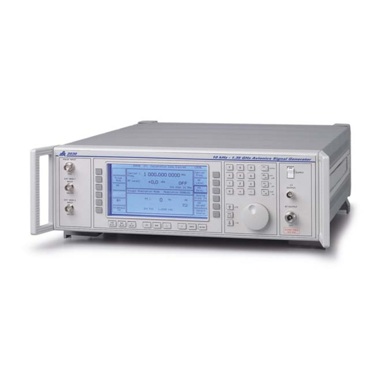
- Page 1 To buy, sell, rent or trade-in this product please click on the link below: http://www.avionteq.com/IFR-AEROFLEX-2030-Series-AM-FM-Signal-Generator.aspx www.avionteq.com AM/FM SIGNAL GENERATORS 2030 Series Operating Manual Document part no. 46891/976...
- Page 2 No part of this document may be reproduced or transmitted in any form or by any means, electronic or mechanical, including photocopying, or recorded by any information storage or retrieval system, without permission in writing by Aeroflex International Ltd. (hereafter referred to throughout the document as ‘Aeroflex’). Printed in the UK Manual part no.
- Page 3 Contents numbers PREFACE PRECAUTIONS Chapter 1 GENERAL INFORMATION Chapter 2 INSTALLATION Chapter 3-1 OPERATION Chapter 3-2 GPIB OPERATION Chapter 4-1 BRIEF TECHNICAL DESCRIPTION Chapter 5-1 ACCEPTANCE TESTING App. 5-1-A ACCEPTANCE TESTING SECOND MODULATION OSCILLATOR OPTION App. 5-1-B ACCEPTANCE TESTING PULSE MODULATION OPTION App.
- Page 4 PREFACE PATENT PROTECTION The 2030 series Signal Generators are protected by the following patents: GB 2030391 GB 2214012 US 4323943 US 4870384 FR 80.26256 GB 1601822 GB 2064892 US 4194164 US 4400630 EP 0125790 GB 2158999 GB 2140232 US 4672336...
-
Page 5: General Information
Precautions These terms have specific meanings in this manual: information to prevent personal injury. WARNING information to prevent damage to the equipment. important general information. Hazard symbols The meaning of hazard symbols appearing on the equipment and in the documentation is as follows: Symbol Description... - Page 6 Fuses Note that there are supply fuses in both the live and neutral wires of the supply lead. If only one of these fuses should rupture, certain parts of the equipment could remain at supply potential. For Option 100, single fuse version only: Fuses Note that the internal supply fuse is in series with the live conductor of the supply lead.
- Page 7 This equipment has been designed and manufactured by Aeroflex to generate low-power RF signals for testing radio communications apparatus. If the equipment is not used in a manner specified by Aeroflex, the protection provided by the equipment may be impaired.
- Page 8 Précautions Les termes suivants ont, dans ce manuel, des significations particulières: WARNING contient des informations pour éviter toute blessure au personnel. contient des informations pour éviter les dommages aux équipements. contient d'importantes informations d'ordre général. Symboles signalant un risque La signification des symboles de danger apparaissant sur l'équipement et dans la documentation est la suivante: Symbole Nature du risque...
- Page 9 Faites effectuer toute réparation par du personnel qualifié. Contacter un des Centres de Maintenance Internationaux dans la liste jointe à la fin du manuel. Fusibles Notez qu’il y a deux fusibles, l’un pour la phase et l’autre pour le neutre du câble d’alimentation. Si un seul fusible est coupé, certaines parties de l’appareil peuvent rester au potentiel d’alimentation.
- Page 10 Utilisation Cet équipement a été conçu et fabriqué par Aeroflex pour générer des signaux RF de faible puissance pour le test d'appareils de radio communications. La protection de l'équipement peut être altérée s'il n'est pas utilisé dans les conditions spécifiées par Aeroflex.
- Page 11 Vorsichtsmaßnahmen Diese Hinweise haben eine bestimmte Bedeutung in diesem Handbuch: WARNING dienen zur Vermeidung von Verletzungsrisiken. dienen dem Schutz der Geräte. enthalten wichtige Informationen. Gefahrensymbole Die Bedeutung der Gefahrensymbole auf den Geräten und in der Dokumentation ist wie folgt: Symbol Gefahrenart Beziehen Sie sich auf die Bedienungsanleitung wenn das Messgerät mit diesem Symbol markiert ist.
- Page 12 Sicherungen Es ist zu beachten, daß es Sicherungen in beiden (spannunsführenden und neutralen) Zuleitungen gibt. Wenn nur eine von diesen Sicherungen schmilzt, so bleiben einige Geräteteile immer noch auf Spannungspotential. Einsicherungs-Option Die interne Sicherung in der Spannungszuführung ist in Reihe mit der spannungsführenden Zuleitung geschaltet.
- Page 13 Dieses Gerät wurde von Aeroflex entwickelt und hergestellt um HF Signale geringer Leistung zum Test von Kommunikationseinrichtungen zu erzeugen. Sollte das Gerät nicht auf die von Aeroflex vorgesehene Art und Weise verwendet werden, kann die Schutzfunktion des Gerätes beeinträchtigt werden.
- Page 14 Precauzioni Questi termini vengono utilizzati in questo manuale con significati specifici: WARNING riportano informazioni atte ad evitare possibili pericoli alla persona. riportano informazioni per evitare possibili pericoli all'apparecchiatura. riportano importanti informazioni di carattere generale. Simboli di pericolo Il significato del simbolo di pericolo riportato sugli strumenti e nella documentazione è il seguente: Simbolo Tipo di pericolo...
- Page 15 Fusibili Notare che entrambi i capi del cavo d’alimentazione sono provvisti di fusibili. In caso di rottura di uno solo dei due fusibili, alcune parti dello strumento potrebbero restare sotto tensione. Opzione singolo fusibile Notare che un fusibile è posto sul filo caldo del cavo di alimentazione. Qualora l’alimentazione avvenga tramite due poli non polarizzati, è...
- Page 16 Caratteristiche d’uso Questo strumento è stato progettato e prodotto da Aeroflex generare segnali RF in bassa potenza per provare apparati di radio comunicazione. Se lo strumento non è utilizzato nel modo specificato da Aeroflex, le protezioni previste sullo strumento potrebbero risultare inefficaci.
- Page 17 Precauciones Estos términos tienen significados específicos en este manual: WARNING contienen información referente a prevención de daños personales. contienen información referente a prevención de daños en equipos. contienen información general importante. Símbolos de peligro El significado de los símbolos de peligro en el equipo y en la documentación es el siguiente: Símbolo Naturaleza del peligro Vea el manual de funcionamiento cuando este símbolo...
- Page 18 Fusibles Se hace notar que el Equipo está dotado de fusibles tanto en el activo como el neutro de alimentación. Si sólo uno de estos fusibles fundiera, existen partes del equipo que pudieran permanecer a tensión de red. Opción fusible único Se hace notar que el fusible de alimentación interno está...
- Page 19 él. Idoneidad de uso Este equipo ha sido diseñado y fabricado por Aeroflex para generar señales de VHF y UHF de bajo nivel de potencia para prueba de equipos de radiocomunicaciones. Si el equipo fuese utilizado de forma diferente a la especificada por Aeroflex, la protección ofrecida por el equipo pudiera quedar reducida.
-
Page 20: Table Of Contents
Frequency selection ..................1-2 Output ......................1-3 Modulation.....................1-3 Incrementing ....................1-3 Sweep......................1-3 Non-volatile memory ..................1-4 Programming....................1-4 Software protection..................1-4 Spectral purity....................1-4 Calibration .....................1-4 Options......................1-4 PERFORMANCE DATA ..................1-7 VERSIONS, OPTIONS AND ACCESSORIES............1-16 LIST OF FIGURES Fig. 1-1 Typical phase noise performance of 2030 Series........1-6... -
Page 21: General Information
GENERAL INFORMATION INTRODUCTION The 2030 series Signal Generators cover the frequency ranges 10 kHz to 5.4 GHz with three models: 2030 (10 kHz to 1.35 GHz), 2031 (10 kHz to 2.7 GHz) and 2032 (10 kHz to 5.4 GHz). A dot matrix display with soft key selected screen options allow flexibility of operation and ease of use. -
Page 22: Output
×10 and ÷10 keys. Sweep The sweep capability of the 2030 Series allows comprehensive testing of systems. Four parameters are used to specify sweep; start, stop, number of steps and time per step. These are specified by the user, with upper and lower limits for the parameter values being dependent on the function. -
Page 23: Non-Volatile Memory
With an SSB phase noise performance of typically -122 dBc/Hz at 470 MHz (20 kHz offset), the 2030 Series can be used for both in-channel and adjacent channel receiver measurements. Harmonically related signals and non-harmonics are better than -30 dBc and -70 dBc respectively. - Page 24 GENERAL INFORMATION Option 005 - GMSK Bt 0.3 Provides GMSK Bt 0.3 modulation at a clock rate of 270.833 kHz in accordance with the GSM and DCS 1800 specifications. The option includes a comprehensive internal data generator. Option 006 - Avionics Provides internally generated modulation waveforms suitable for the testing of Instrument Landing Systems (ILS) and VHF Omni Range (VOR) beacons.
-
Page 25: Fig. 1-1 Typical Phase Noise Performance Of 2030 Series
Typical performance at 500MHz SSB Phase SSB Phase -100 Noise (dBc/Hz) -120 Noise (dBc/Hz) -110 -120 -130 -130 -140 -150 -140 -160 1000 2000 100k Carrier Frequency (MHz) Frequency Offset (Hz) C0079 Fig. 1-1 Typical phase noise performance of 2030 Series... -
Page 26: Performance Data
GENERAL INFORMATION PERFORMANCE DATA CARRIER FREQUENCY Range 10 kHz to 1.35 GHz (2030); 10 kHz to 2.7 GHz (2031); 10 kHz to 5.4 GHz (2032). By keyboard entry of data. Variation by ⇑/⇓ keys and by rotary Selection control. Indication 11 digits with annunciators. - Page 27 GENERAL INFORMATION At 22 ±5 °C ambient: Accuracy Carrier frequency range Output level 10 kHz 1.35 GHz 2.7 GHz 1.35 GHz 2.7 GHz 5.4 GHz > −127 dBm ±0.85 dB ±1.0 dB > −100 dBm ±0.85 dB ±1.0 dB ±1.5 dB >...
- Page 28 GENERAL INFORMATION SPECTRAL PURITY At RF levels up to +7 dBm : Harmonics 2030, 2031: Better than -30 dBc for carrier frequencies to 1 GHz; Better than -27 dBc for carrier frequencies above 1 GHz. 2032: Better than -30 dBc for carrier frequencies to 1 GHz. Better than -27 dBc for carrier frequencies to 1.35 GHz.
- Page 29 GENERAL INFORMATION FREQUENCY MODULATION Deviation Peak deviation from 0 to 1 MHz for carrier frequencies up to 21.09375 MHz; Peak deviation from 0 to 1% of carrier frequency above 21.09375 MHz. By keyboard entry of data. Variation by ⇑/⇓ keys and by rotary Selection control.
- Page 30 GENERAL INFORMATION AMPLITUDE MODULATION For carrier frequencies up to 1 GHz (and for output levels less than +13 dBm with Option 003): Range 0 to 99.9%. By keyboard entry of data. Variation by ⇑/⇓ keys and by rotary Selection control. Indication 3 digits with annunciator.
- Page 31 GENERAL INFORMATION LF OUTPUT Front panel BNC connector. The output may be configured in either LF Generator Mode to give an output from the internal modulation oscillator or in LF Monitor Mode to give an output from the internal modulation signal paths. By keyboard entry of data.
-
Page 32: Installation
GENERAL INFORMATION GPIB INTERFACE A GPIB interface is fitted. All functions except the supply switch are remotely programmable. Capabilities Complies with the following subsets as defined in IEEE Std. 488.1. SH1, AH1, T6, L4, SR1, RL1, PP0, DC1, DT1, C0, E2. Conforms with the protection requirements of EEC Council ELECTRO-MAGNETIC Directive 2004/108/EC. - Page 33 GENERAL INFORMATION SECOND MODULATION Specification as Modulation Oscillator. OSCILLATOR OPTION Ω The EXT MOD 2 INPUT socket has a 600 Ω input impedance in EXT MOD 2 INPUT 600 OPTION place of 100 kΩ. PULSE MODULATION (OPTION 002 and 105) Modulation modes Pulse modulation may be used alone or in conjunction with FM, ΦM or Wideband FM.
- Page 34 GENERAL INFORMATION AVIONICS OPTION See Annex B. RF PROFILES AND COMPLEX SWEEP OPTION See Annex C. PULSE GENERATOR See Annex D. DME MODULATOR See Annex E. 1-15...
-
Page 35: Versions, Options And Accessories
AC supply lead (see 'Power cords', Chap. 2). 46881/976 Operating manual (this manual) for 2030 series. Optional accessories 46880/047 Service manual for 2030 series (consists of operating manual plus maintenance manual). RF connector cable, 50 Ω, 1.5 m, BNC. 43126/012 54311/092 Coaxial adapter N-type male to BNC female. -
Page 36: Ec Declaration Of Conformity
GENERAL INFORMATION EC Declaration of Conformity Certificate Ref. No.: DC218 The undersigned, representing: Manufacturer: Aeroflex International Ltd. Address: Longacres House, Six Hills Way, Stevenage, Hertfordshire, UK SG1 2AN Herewith declares that the product: Equipment Description: Signal Generators 2030, 2031, 2032, 2040, 2041 and 2042 Model No. - Page 37 Chapter 2 INSTALLATION CONTENTS PAGE INITIAL VISUAL INSPECTION ................2-2 MOUNTING ARRANGEMENTS ................2-2 INSTALLATION REQUIREMENTS..............2-2 Ventilation ....................2-2 Class I power cords (3-core) ................. 2-2 GOODS-IN CHECKS ....................2-5 CONNECTING TO SUPPLY .................. 2-5 Voltage selector .................... 2-6 Fuses ......................
-
Page 38: Installation
In the event that a moulded plug has to be removed from a lead, it must be disposed of immediately. A plug with bare flexible cords is hazardous if engaged in a live socket outlet. Power cords with the following terminations are available from Aeroflex. Please check with your local sales office for availability. - Page 39 INSTALLATION British The UK lead is fitted with an ASTA approved moulded plug to BS 1363. Country IEC 320 plug type Part number United Kingdom Straight through 23422/001 United Kingdom Right angled 23422/002 EARTH NEUTRAL A replaceable 13 A fuse to BS 1362 is contained within the plug. LIVE This fuse is only designed to protect the lead assembly.
- Page 40 INSTALLATION Français Le câble d'alimentation d'Europe Continentale est muni d'un connecteur mâle à angle droit type CEI83, standard C4 (CEE 7/7), qui peut être utilisé dans une prise femelle à ergot de terre (standard C 3b) ou à clips latéraux (standard C 2b), cette dernière étant communément appelée prise “Schuko”...
-
Page 41: Goods-In Checks
1 Inspect the shipping container and instrument for any signs of damage. If damage is evident, do not plug in, turn on or attempt to operate the instrument. Repackage it and return it to Aeroflex. 2 Verify that your order is complete, including any accessories and options that you may have ordered. -
Page 42: Voltage Selector
Fig. 2-1 AC connector showing voltage selector and fuse holders GENERAL PURPOSE INTERFACE BUS (GPIB) The GPIB interface built into the 2030 series enables the signal generators to be remotely controlled to form part of an automatic measuring system. GPIB cable connection Connection to other equipment which has a 24-way connector to IEEE Standard 488 is made using the rear panel GPIB socket. -
Page 43: Gpib Connector Contact Assignments
INSTALLATION GPIB connector contact assignments The contact assignments of the GPIB cable connector and the device connector are as shown in Fig. 2-2. Contact Function Contact Function Data I/O 1 DataI/O 5 Data I/O 2 DataI/O 6 Data I/O 3 DataI/O 7 Data I/O 4 DataI/O 8... -
Page 44: Interface Bus Connection
The replacement battery should be SAFT L56 or equivalent. This is a lithium 3.5 V type, rated at 1800 mAH, size AA. If a lithium battery is unobtainable an alkaline battery can be used but it will have a shorter life. A suitable battery can be obtained from Aeroflex (part number 23711/106). - Page 45 INSTALLATION Prior to carrying out any inspection and tests, the instruments must be disconnected from the mains supply and all external signal connections removed. All tests should include the instrument’s own supply lead, all covers must be fitted and the equipment supply switch must be in the ‘ON’...
-
Page 46: Cleaning
The above information is provided for guidance only. Aeroflex designs and constructs its products in accordance with International Safety Standards such that in normal use they represent no hazard to the operator. Aeroflex reserves the right to amend the above information in the course of its continuing commitment to product safety. - Page 47 Chapter 3-1 OPERATION CONTENTS PAGE INTRODUCTION ....................3-1-4 CONVENTIONS ...................... 3-1-4 FRONT PANEL......................3-1-4 REAR PANEL ......................3-1-6 THE MENUS......................3-1-7 FIRST TIME USE ....................3-1-9 Switching on ....................3-1-9 Changing the value of the selected parameter ..........3-1-10 Enabling or disabling the modulation ............3-1-11 Using the [⇑...
- Page 48 OPERATION Setting the GPIB address ................3-1-41 Sequential calling tones ................3-1-41 Carrier phase adjustment ................3-1-41 Selection of frequency standard..............3-1-42 Selection menu 2................... 3-1-42 Calibration ....................3-1-43 Latch data...................... 3-1-43 Elapsed time....................3-1-43 Locking and unlocking ................. 3-1-44 Setting time and date..................
- Page 49 OPERATION Fig. 3-1-16 Sequential calling tones utility menu (DTMF mode) ......3-1-28 Fig. 3-1-17 Calling tones mode control menu (with [FM] selected) ....... 3-1-29 Fig. 3-1-18 Tone standard selection menu............... 3-1-30 Fig. 3-1-19 Edit sequential tones standard menu............. 3-1-31 Fig. 3-1-20 Total shift menu ..................3-1-32 Fig.
-
Page 50: Introduction
OPERATION INTRODUCTION This chapter explains how to: • Set up the signal generator to produce a typical basic signal. • Select the main operating parameters; carrier frequency, output level and type of modulation. • Use the full range of supporting facilities. Note... - Page 51 OPERATION SUPPLY Switches the AC supply voltage on and off. CARR ON-OFF Enables or disables the carrier frequency. MOD ON-OFF Enables or disables the modulation. LF ON-OFF Switches the low frequency output on and off. UTIL Displays the utilities menu. Displays the memory store/recall menu.
-
Page 52: Rear Panel
OPERATION REAR PANEL The following facilities are available on the rear panel, see Fig. 3-1-2. ------------ ------------ TRIGGER WIDE BAND FREQ STD MARKER RAMP FM IN IN/OUT SWEEP FUSE 100/120V~ TT1.6AL250V GPIB RATING 220/240V~ TT1AL250V POWER SUPPLY 220Vac 100/120/220/240V~ 240Vac 50-400Hz 180VA MAX î... -
Page 53: The Menus
OPERATION THE MENUS The 2030 Series instruments are operated by calling up various displays or menus on the screen. Menus are accessed via both hard and soft keys. Pressing a hard key normally causes the appropriate primary menu to appear on the screen regardless of the current working position within the menu hierarchy. - Page 54 OPERATION LOCAL Carrier Carrier : 5 400.000 0000 Freq. Freq. Intermod. RF Level : Level -144.0 Int Std: 10 MHz Devn. Single Modulation Mode Modulation ENABLED Source Freq: F4 ΦM ON/OFF Int F4 : 1.0000 kHz Wideband Select Source C0483 Fig.
-
Page 55: First Time Use
OPERATION FIRST TIME USE First time users can quickly become familiar with the principles of control and display by carrying out the following exercise, which demonstrates how to set up a typical basic signal having the following parameters: Carrier frequency: 100 MHz. -
Page 56: Changing The Value Of The Selected Parameter
OPERATION Changing the value of the selected parameter If an error is made when keying in, press the soft key again and key in the correct value. If an error message is displayed, it can be cancelled by entering a value which is within limits. Using the numerical key pad, enter 100 MHz by pressing keys [1], [0], [0] and the key marked [MHz/mV/ms]. -
Page 57: Enabling Or Disabling The Modulation
OPERATION Enabling or disabling the modulation The modulation is ON by default, but the AM can be turned ON and OFF by pressing [AM ON/OFF] at the right hand side of the display and the modulation can be enabled or disabled by pressing [MOD ON-OFF]. -
Page 58: Detailed Operation
OPERATION DETAILED OPERATION CARRIER FREQUENCY The carrier frequency is selected from the Sig Gen menu by pressing [Carrier Freq.], unless it is already highlighted as in the default display. Enter the required value via the numerical key pad. The value can then be incremented or decremented using the control knob and its associated keys, [KNOB UP-DN], [×10] and [÷10]. -
Page 59: Reverse Power Protection
OPERATION Reverse power protection Accidental application of power to the RF OUTPUT socket trips the reverse power protection circuit (RPP) and a flashing message appears on the display, see Fig. 3-1-7. reset *** REMOVE SIGNAL SOURCE *** C0004 Fig. 3-1-7 RPP tripped Pressing [RPP Reset] resets the RPP and returns the display to the menu in use when the reverse power protection was tripped. -
Page 60: Modulation Modes
OPERATION MODULATION MODES Two independent inputs on the front panel EXT MOD 1 INPUT, EXT MOD 2 INPUT allow external modulation signals to be summed with signals from the internal oscillator and a second optional internal oscillator (if fitted). Thus up to four modulations may be available at one time. -
Page 61: Modulation Mode Selection
OPERATION Modulation mode selection In order to select a different modulation mode; Press [UTIL]. Utilities Selection Menu 1 will appear on the display. Press the [Mod'n Mode] key. This calls up the Modulation Mode Selection Menu shown in Fig. 3-1-8. The four possible modulation modes are shown. Press the required soft key. -
Page 62: Selecting The Modulation
OPERATION LOCAL Carrier Carrier : 2 700.000 0000 Freq. Freq. Intermod. RF Level : Level -144.0 Int Std: 10 MHz Devn. Single Composite Mode Modulation ENABLED Source Freq: F4 2.50 FM1: Hz ON FM1: kHz ON Φ ON/OFF Int F4 : 1.0000 kHz Int F2 : 400.0 Hz... -
Page 63: Selecting Amplitude Modulation
OPERATION Selecting amplitude modulation At the Sig Gen menu, press [AM], the [AM Depth] box is now highlighted. Enter the required modulation depth via the numerical key pad and terminate with the [%] key. If the modulation depth requested exceeds 99.9%, the depth is reset to the maximum value available and the message: ERROR 56: AM Outside Limits is displayed at the top of the screen. -
Page 64: Selecting Wideband Frequency Modulation
OPERATION Selecting wideband frequency modulation At the Sig Gen menu, press [Wideband FM]. The [Wideband FM] box will be highlighted. The value can be changed via the key pad and frequency terminator key. To preserve the widest bandwidth, the control of the wideband FM is carried out in a series of fixed steps and the signal generator automatically displays the calculated fixed step which is closest to the keyed in value. -
Page 65: Source Selection - Internal
OPERATION Source selection - internal The modulation source may be selected by pressing [Select Source]. Sources may be internal or external. If the currently selected source is internal, the Internal Source Selection Menu is displayed, giving a choice of six frequencies, F1-F6, see Fig. 3-1-10. The frequency assigned to the highlighted F number may be changed by the numerical key pad and terminated with [Hz], [kHz], [MHz] or [GHz]. - Page 66 OPERATION LF phase When an internal source has been selected, its phase relative to the second modulation oscillator (if fitted) can be changed by pressing [Mod. Src Phase] and entering the required value. Where two internal modulation frequencies are active, the starting phase difference between the two signals can be set up and the phase angle is referred to the currently selected oscillator.
-
Page 67: Source Selection - External
OPERATION Source selection - external An external source may be selected by pressing [Select External]. The External Source Selection Menu is then displayed on the screen (This menu is displayed immediately when pressing [Select Source] if the currently selected source is external). This menu allows the choice of two input sockets EXT MOD 1 INPUT and EXT MOD 2 INPUT and AC, ALC, or DC coupling by pressing the appropriate soft key. -
Page 68: Modulation Alc
OPERATION MODULATION ALC The automatic levelling control (ALC) is used in conjunction with an external source and can be disabled when not required. To enable the ALC, proceed as follows: At the Sig Gen menu, press [Select Source]. The display will show the Internal or External Source Selection Menu (Fig. -
Page 69: Pulse Modulation
OPERATION PULSE MODULATION (applies if Option 002 is fitted) Enabling the pulse modulation disables the RF ALC system which is used to control the output level from the generator. The signal generator sets the requested RF output level using a digitally derived control signal whose level is equivalent to that which would be generated by the RF ALC system. -
Page 70: Selecting Pulse Modulation
OPERATION Selecting pulse modulation From the Sig Gen menu press [Pulse Mod] to obtain the Pulse Mod display shown in Fig. 3-1-13. Notes... The [RF Level Autocal] key will only appear if the CW burst suppression mode has been enabled in which case a temporary calibration display will appear for approximately 1.5 s while calibration is undertaken. -
Page 71: Low Intermodulation Mode
OPERATION Low intermodulation mode When carrying out intermodulation tests the output signal from two signal generators is combined using a resistive or hybrid combiner. If the carrier frequencies are relatively close together each generator will receive an interfering signal from the other source. The RF ALC system will detect a beat frequency equal to the difference in carrier frequencies and attempt to apply AM in order to cancel the signal. -
Page 72: Signalling
OPERATION SIGNALLING CTCSS A CTCSS tone is any one of 32 standard sub-audible tones ranging from 67 Hz to 250.3 Hz and would generally be used in conjunction with an audible modulation signal in a composite modulation mode. The procedure for initiating these tones is as follows: Tone selection At the Sig Gen menu, press [Select Source]. -
Page 73: Sequential Calling Tones
OPERATION Note... Selecting [CTCSS1], [CTCSS2], [USER] or [TEMP] from the Tone Standard Selection Menu causes the pictogram in the Continuous Tone Selection Menu and the Internal Source Selection Menu to change e.g. ctc1. The pictogram is repeated in the modulation section of the Sig Gen menu. - Page 74 C1890 Fig. 3-1-16 Sequential calling tones utility menu (DTMF mode) On 2030 series fitted with the second modulation oscillator (Option 001) the DTMF signalling capability is also provided. If this standard is selected then the main menu accessed after pressing the [Calling Tones] soft key at Utilities Selection Menu 1 will be as shown in Fig.
- Page 75 OPERATION [Tone Duration] The default duration of 70 ms for each tone in the sequence can be changed by pressing this key, entering the required duration value and pressing [ms]. [Tone Gap] The default gap duration of 70 ms between each tone in the sequence can be changed by pressing this key, entering the required gap length and pressing [ms].
- Page 76 OPERATION Selecting alternative tone standards The [Select Standard] key causes the Tone Standard Selection Menu to be displayed, see Fig. 3-1-18. LOCAL CCIR Tone Standard Selection Menu EURO Current Standard: CCIR Tone 0: 1.9810 kHz Tone 8: 1.7470 kHz DZVEI NATEL Tone 1: 1.1240 kHz Tone 9: 1.8600 kHz...
- Page 77 OPERATION Finally store the user defined tone system parameters in USER1 or USER2 by pressing [Store to USER1] or [Store to USER2]. Note that when using the DTMF tone signalling capability no editing facility is provided. Changes to the default settings are made directly on the Calling Tones Utility Menu. Fig.
-
Page 78: Displaying Shifts
OPERATION (using Δ) INCREMENTING Displaying shifts Press the [Δ] hard key. The total shift menu is displayed as shown in Fig. 3-1-20. This menu displays the difference between the current value and the keyed-in value. Parameters can be incremented or decremented by using the [⇑] or [⇓] key or the control knob, see 'Using the control knob' on Page 3-1-11. -
Page 79: Sweep
OPERATION SWEEP The sweep capability allows the comprehensive testing of systems, as measurements at single points will not necessarily give an overall indication of the performance. The sweep function is specified by the following parameters: • Start value • Stop value •... - Page 80 OPERATION LOCAL LF Freq Carrier Sweep Sweep Sweep Type Menu RF Level LF Level Sweep Sweep Current Sweep Type: RF LEVEL Int. F4 Sweep Sweep EXIT C0052 Fig. 3-1-22 Sweep type menu The instrument must be in the LF generator mode before an LF frequency sweep and LF level sweep can be initiated.
-
Page 81: Sweep Mode
OPERATION Sweep mode At the sweep parameters menu, press [Sweep Mode]. The Sweep Trigger Mode Menu is displayed, see Fig. 3-1-23. LOCAL Internal Single Sweep Trigger Mode Menu Internal Cont. Current Sweep Mode: INTERNAL SINGLE External Trigger EXIT C0017 Fig. 3-1-23 Sweep trigger mode menu Select the sweep mode, [Internal Single], [Internal Cont.], or [External Trigger]. - Page 82 OPERATION Number of steps Select [Number of Steps]. Enter the number of steps via the numerical key pad and the [GHz/V/enter] terminator key. Note... If an inappropriate number of steps is selected, the instrument will automatically choose a more reasonable value. The number of steps available depends on the operating mode and the maximum values are: for carrier frequency with FM, ΦM or Wideband FM enabled for carrier frequency without FM, ΦM or Wideband FM enabled.
-
Page 83: Sweep Control
OPERATION Sweep control Starting the sweep From the sweep parameters menu, press [Start Sweep]. The single sweep status line display changes from WAITING FOR TRIGGER to SWEEPING and a solid bar increments to show the sweep progression, see Fig. 3-1-25. LOCAL Stop Level Start:... - Page 84 OPERATION LOCAL Stop Level Start: -144.0 Sweep Reset Level Stop: +13.0 Sweep Number of: 1000 ----- Transfer Steps Step Time: Sweep Status: PAUSED AT +6.4 dBm Sweep Mode: INTERNAL SINGLE Sweep Type: RF LEVEL C1901 Fig. 3-1-26 Sweep stopped LOCAL Carrier 626.407 6800 Carrier :...
-
Page 85: Utilities
OPERATION UTILITIES The utilities options are accessible from two primary menus, Utilities Selection Menu 1 and Utilities Selection Menu 2. When a selection is made from either of these menus and [UTIL] is subsequently pressed, the primary menu is re-displayed. However, if instead a selection is made and then one of the other hard keys e.g. -
Page 86: Adjusting The Display
OPERATION Adjusting the display To adjust the display, press [Display Adjust]. The Display Adjust menu is displayed on the screen, see Fig. 3-1-29. The backlight, which is on when the instrument is switched ON, can be toggled ON or OFF using the [Display ON/OFF] key, and when ON can be varied in brightness by [Dim], [Medium 1], [Medium 2] and [Bright]. -
Page 87: External Trigger
OPERATION External trigger The external trigger facility allows the rear panel TRIGGER input to be set up so as to initiate a defined change in the generator setting. To define the function press [External Trigger]. The display changes to show the External Trigger Selection Menu which has the following options: [Sweep Start] Starts the external sweep. -
Page 88: Selection Of Frequency Standard
OPERATION Selection of frequency standard Pressing [Int/Ext Standard] changes the menu to display the Frequency Standard Selection Menu which controls the internal/external frequency standard facilities. The signal generator can be set to operate from an external standard or from the internal standard with or without the standard being provided on the rear panel FREQ STD IN/OUT connector. -
Page 89: Calibration
OPERATION Calibration Pressing [Cal. Value] brings the Calibration Utilities Menu to the display, see Fig. 3-1-31. This menu shows when the last complete check was made and when the next calibration check is due. It also shows the date on which the individual items were adjusted. It is possible to inspect the calibration value of these items but calibration cannot be carried out unless the protection facility is unlocked at Level 2. -
Page 90: Locking And Unlocking
OPERATION Locking and unlocking Press [Lock & Unlock]. When Level 1 and Level 2 are both locked, the menu displays three soft keys: Unlock Level 1 Unlock Level 2 Serial No. Set Press [Unlock Level 1] and the message Enter 4 Digit Password: will appear on the display. -
Page 91: Setting Time And Date
Display blanking To prevent sensitive data from being displayed, the 2030 Series Signal Generators include a display blanking facility. This allows various parts of the display to be replaced by a series of dashes so that values entered by the user or recalled from the memory will not be visible. The instrument must be unlocked to Level 2 to enable or disable this facility. -
Page 92: Rf Level Units
OPERATION RF level units RF output level units can be altered using the [Level Units] key. The level units may be entered as an EMF or PD, and the logarithmic units can be referred to volts (dBV), millivolts (dBmV), microvolts (dBμV) or to 1 milliwatt into 50 Ω(dBm). Select the units by pressing [Level Units] which displays the RF Level Units Selection Menu shown in Fig. -
Page 93: Lf Level Units
OPERATION LF level units LF level logarithmic units may be referenced to 1 volt EMF (dBV EMF), 1 millivolt EMF (dBmV EMF) or 1 milliwatt into 600 Ω(dBm). Linear units are always set EMF values. Select the units by pressing the [LF Level Units] soft key on the RF Level Units Selection Menu which calls up the LF Level Units Selection Menu shown in Fig. -
Page 94: Rf Level Utility
OPERATION RF level utility Selecting [RF Level Utility] from the Utilities Selection Menu 2 displays the RF Level Utility Menu shown in Fig. 3-1-34. LOCAL RF Level Utility Menu Extended Extended Hysteresis : ENABLED Offsets CW Burst RF Level CW Burst Suppression : ENABLED Control Limit... - Page 95 OPERATION +13 dBm +6 dBm 0 dBm -24 dBm -18 dBm -12 dBm -6 dBm 0 dBm +13 dBm 0 dB Requested output level 6 dB 12 dB 18 dB C0956 24 dB Fig. 3-1-35 Normal signal generator level control operation +12 dBm +6 dBm 0 dBm...
- Page 96 OPERATION RF offset With the instrument unlocked to Level 1, see 'Locking and unlocking' above, pressing [Offsets] produces the layout for the soft keys shown in Fig. 3-1-37. LOCAL Carrier Save Carrier : 1 050.000 000 Freq. Offset Feq. Enable/ Offset -102.0 Disable...
- Page 97 OPERATION RF level limit With the instrument unlocked to level 1, see 'Locking and unlocking' above, pressing the [RF Level Limit] key causes the RF Level Limit Menu shown in Fig. 3-1-38 to be displayed. LOCAL Save RF level RF Level Limit Menu Setting Limit Enable/...
-
Page 98: Low Frequency Operation
OPERATION LOW FREQUENCY OPERATION The instrument has two modes of LF operation. The LF output can be used either as a modulation signal monitor or as an independent low frequency generator. Pressing [LF] displays either the LF Monitor Menu or the LF Generator Menu, depending on which mode was last selected. -
Page 99: Use As An Independent Lf Generator
OPERATION Use as an independent LF generator To use the instrument as an independent LF generator, select [LF Gen.] at the LF Monitor Menu. The LF Generator Menu appears on the display as shown in Fig. 3-1-39. Fig. 3-1-39 LF generator menu In this mode, one internal oscillator must be used exclusively for this task. -
Page 100: Memory
OPERATION MEMORY Memory recall Pressing the [MEM] hard key after switch on, causes the Memory Recall Menu, Fig. 3-1-40, to be displayed. There are four types of recall, full, partial, carrier frequency and sweep. Provision is made for an option not to recall the carrier frequency for full and partial stores. -
Page 101: Memory Stepping Facility
OPERATION Sweep recall The sweep store has 20 locations (numbered 0 to 19) containing complete sets of sweep parameters which may be recalled when required. Note... Sweep parameters can be recalled whether the instrument is in sweep mode or not. They are only used when sweep is selected. - Page 102 OPERATION FULL 48 LOCAL Carrier : 2 700.000 0000 Freq. RF Level : -144.0 Memory Int Std: 10 MHz Single Modulation Mode Modulation ENABLED Memory Down Memory Return Int F4 : 1.0000 kHz C0955 Fig. 3-1-41 Memory stepping menu Pressing [Memory Up] or [Memory Down] respectively increments or decrements the memory location.
-
Page 103: Memory Store
OPERATION Memory store Pressing the [Memory Store] soft key on the Memory Recall Menu causes the Memory Store Menu, Fig. 3-1-42, to be displayed. There are four types of store, full, partial, carrier frequency and sweep. To prevent the accidental overwriting of memory contents, a store protection facility is provided. - Page 104 OPERATION Full store Selecting [Full Store] enables the storage of a complete instrument setting, i.e. carrier frequency, RF level, modulations and their increments, ON/OFF and source information. Also stored are all 6 modulation oscillator frequencies, plus one increment, and the LF Generator Monitor setting.
- Page 105 OPERATION Storing data To store data, press the soft key for the type of store required, e.g. [Partial Store] and define a store location via the numerical key pad, then press [enter]. Note... The settings for the sequential calling tones are stored via the calling tones menu in UTILITIES, see Fig.
-
Page 106: Frequency Hopping
OPERATION Frequency hopping Carrier frequency hopping is a GPIB operation where the instrument can be instructed to hop between any of the frequencies contained in the carrier frequency stores and a sequence of up to 1024 hops may be entered. The time interval between hops can also be entered . Before executing a carrier hopping sequence, the frequencies must be loaded into the carrier frequency stores (0 - 99). - Page 107 OPERATION Note:... If any of the carrier frequency stores have become corrupt and so result in a checksum error, the following message will appear in the centre of the screen: CARRIER STORE < x > CORRUPTED. RE - ENTER FREQUENCY. where x is the corrupted store number.
- Page 108 OPERATION Like other sweep settings the frequency hopping mode can be set to: single sweep (internal trigger), continuous sweep (internal trigger) or external sweep (external trigger) by using the following commands: SWEEP:MODE SNGL SWEEP:MODE CONT SWEEP:MODE EXT For externally triggered operation the trigger facility can be used in the same manner as another sweep function.
-
Page 109: Error Handling
OPERATION ERROR HANDLING Errors may be divided into three groups - foreground errors generally caused by a user, background errors which represent a condition of the instrument and GPIB errors which occur only when the unit is being controlled by a GPIB controller. Background errors An incorrect operating condition within the instrument automatically generates an error message to warn the operator. -
Page 110: Table 3-1-2 Background Errors
OPERATION Table 3-1-2 Background errors Error Error Descriptive text Descriptive text Type No. Type RPP Tripped VCXO Out of Lock Fractional N Out of Lock Ext1 Too Low Int. Standard Failure Ext1 Too High Ext. Standard Failure Ext2 Too Low Incorrect Ext. -
Page 111: Table 3-1-4 Gpib Errors
OPERATION Table 3-1-3 Foreground errors (continued) Attenuator EAROM Write EAROM Wrap Around Error RF Option Box EAROM Read Continuous Tone Checksum RF Option Box EAROM Write Sequential Tone Checksum EAROM Write Error Tone data Out of Range EAROM Read Error Tone Offset Out of Range Clock Data Entry Error RF levelling fault... -
Page 112: Table 3-1-5 Fatal Errors
OPERATION Table 3-1-5 Fatal errors Error Error Descriptive text Descriptive text Type Type Main RAM Faulty Main PROM Faulty Microwave Board Error Attenuator Type Unknown Wrong Attenuator fitted 3-1-66... - Page 113 Chapter 3-2 GPIB OPERATION CONTENTS PAGE INTRODUCTION .......................3-2-2 INTRODUCTION .......................3-2-2 GPIB FUNCTIONS .....................3-2-2 DEVICE LISTENING ELEMENTS ................3-2-3 DEVICE TALKING ELEMENTS ................3-2-3 PROGRAMMING .......................3-2-4 Program messages....................3-2-4 Compound headers...................3-2-4 Program data ....................3-2-5 Message exchange protocol ................3-2-5 Remote/local operation ..................3-2-5 Common commands and queries (IEEE 488.2)..........3-2-6 DEVICE DEPENDENT COMMANDS..............3-2-8 DEFAULT SETTINGS ....................3-2-8 INSTRUMENT MODE .....................3-2-10...
-
Page 114: Gpib Operation
GPIB OPERATION INTRODUCTION The 2030 Series signal generators can be operated remotely from a personal computer fitted with a GPIB interface card or a dedicated GPIB controller. All functions can be controlled by coded messages sent over the interface bus via the 24-way socket on the rear panel of the instrument. -
Page 115: Device Listening Elements
GPIB OPERATION DEVICE LISTENING ELEMENTS The following is a list of the device listening elements (as defined in the IEEE 488.2 standard) which are used in the 2030 Series of signal generators: <PROGRAM MESSAGE> <PROGRAM MESSAGE TERMINATOR> <PROGRAM MESSAGE UNIT>... -
Page 116: Programming
2030 Series in the same way). Compound headers The 2030 Series implements compound headers which allow a complex set of commands to be built up from a small set of basic elements in a 'tree and branch' structure. The elements of a compound header are separated by a colon (:). -
Page 117: Program Data
DEADLOCK (error 118) can only occur if the input and output buffers are both filled by the controller having sent an extra long Message containing several query message units. The 2030 Series have input buffer stores of 256 characters and an output buffer of two response message units. -
Page 118: Common Commands And Queries (Ieee 488.2)
Common command and query mnemonics are preceded by an asterisk (*) to distinguish them from device dependent data such as instrument programming strings. The following common commands and queries are implemented in the 2030 Series: Mnemonic Name and Description *IDN? Identification Query. - Page 119 GPIB OPERATION *SRE <nrf> Service Request Enable Command. Sets the Service Request Enable Register. *SRE? Service Request Enable Query. Returns the value of the Service Request Enable Register as nr1. *ESR? Standard Event Status Register Query. Returns the value of the Status Event Status Register as nr1.
-
Page 120: Device Dependent Commands
Each group is followed by a list of requirements for data type and suffix. In addition to the normal listen commands the 2030 Series accept query commands which cause the instrument to prepare a message which will be sent to the controller when the instrument is next addressed to talk. - Page 121 GPIB OPERATION TABLE 3-2-1 INSTRUMENT DEFAULT SETTINGS (continued) Modulations 0 Hz, Int F4, ON 0 Hz, Ext 1 ALC, ON ΦM1 0 rad, Int F4, ON ΦM2 0 rad, Ext 1 ALC, ON 0%, Int F4, ON 0%, Ext 2 ALC, ON WBFM : (Minimum setting), AC coupled, ON ΔFM 1 kHz, ΔΦM 0.1 rad, ΔAM 1%...
-
Page 122: Instrument Mode
GPIB OPERATION INSTRUMENT MODE IMODE Select instrument mode Character Program Data (either NORMAL for signal generator Data type : operation or SWEEPER for swept operation) None Allowed suffices : None Default suffix : Example: IMODE NORMAL CARRIER FREQUENCY CFRQ Set Carrier Frequency (short form) Set Carrier Frequency :VALUE Set Carrier Frequency step... -
Page 123: Rf Level
GPIB OPERATION RF LEVEL RFLV Set RF output level (short form) Set RF output level :VALUE Data type : Decimal Numeric Program Data Any one of: DBM, DBV, DBMV, DBUV, V, MV or UV Allowed suffices : dBm unless changed by UNITS command Default suffix : :INC Set RF level step (dB) - Page 124 GPIB OPERATION RFLV? Prepares message containing information on RF Level setting in the following format: :RFLV:UNITS <unit>;TYPE <type>;VALUE <nr2>;INC <nr2>;<status> where: <unit> is character program data defining the default RF level units (DBM, DBV, DBMV, DBUV, V, MV or UV), <type> is character program data indicating EMF or PD and <status>...
- Page 125 GPIB OPERATION RFLV:LIMIT? Prepares message containing information on RF level setting in the following format: :RFLV:UNITS <unit>;TYPE <type>;LIMIT:VALUE<nr2>;<status> where: <unit> is character program data defining the default RF level units (DBM, DBV, DBMV, DBUV, V, MV or UV), <type> is character program data indicating EMF or PD and <status>...
-
Page 126: Modulation Mode
GPIB OPERATION MODULATION MODE MODE Set modulation mode Character Program Data (valid combinations of AM, AM1, Data type : AM2, FM, FM1, FM2, PM, PM1, PM2, WBFM or PULSE, see Table below) None Allowed suffices : None Default suffix : Examples: MODE AM,FM MODE FM1,FM2... -
Page 127: Modulation Control
GPIB OPERATION MODULATION CONTROL [not used alone] Turn modulation globally ON Turn modulation globally OFF :OFF Examples: MOD:ON MOD:OFF MOD? Prepares message containing information on Modulation Control in the following format: :MOD:<status> where: <status> is a program mnemonic indicating whether the Modulation is globally ON or OFF. -
Page 128: Frequency Modulation
GPIB OPERATION FREQUENCY MODULATION FM or FM1 or FM2 Set FM deviation (short form) Set FM deviation :DEVN Set FM step size :INC Data type : Decimal Numeric Program Data Any one of: GHZ, MHZ, KHZ or HZ Allowed suffices : Default suffix : :<src>... -
Page 129: Phase Modulation
GPIB OPERATION PHASE MODULATION PM or PM1 or PM2 Set Phase deviation (short form) Set Phase deviation :DEVN Set Phase Modulation step size :INC Data type : Decimal Numeric Program Data RAD or RADS Allowed suffices : Default suffix : :<src>... -
Page 130: Amplitude Modulation
GPIB OPERATION AMPLITUDE MODULATION AM or AM1 or AM2 Set AM Depth (short form) Set AM Depth :DEPTH Set AM step size :INC Data type : Decimal Numeric Program Data Allowed suffices : Default suffix : :<src> Select modulation source where <src> is any one of: INTF1, INTF2, INTF3, INTF4, INTF5, INTF6, EXT1DC, EXT1AC, EXT1ALC, EXT2DC, EXT2AC or EXT2ALC Turn AM ON (local) -
Page 131: Wideband Fm
GPIB OPERATION WIDEBAND FM WBFM Set WBFM deviation (short form) Set WBFM deviation :DEVN Data type : Decimal Numeric Program Data Any one of: GHZ, MHZ, KHZ or HZ Allowed suffices : Default suffix : Turn WBFM ON (local) Turn WBFM OFF (local) :OFF Select AC coupling Select DC coupling... -
Page 132: Pulse Modulation
GPIB OPERATION PULSE MODULATION PULSE [not used alone] Turn Pulse modulation ON Turn Pulse modulation OFF and select Low Intermodulation :OFF Enable CW burst suppression mode :CAL:ENABLE Disable CW burst suppression mode :DISABLE Data type : None None Allowed suffices : None Default suffix : Examples:... -
Page 133: Modulation Frequency
GPIB OPERATION MODULATION FREQUENCY INTF1 or INTF2 or INTF3 or Set modulation oscillator frequency (short form) INTF4 or INTF5 or INTF6 Set modulation oscillator frequency :FREQ Set modulation oscillator frequency step size :INC Data type : Decimal Numeric Program Data Any one of: GHZ, MHZ, KHZ or HZ Allowed suffices : Default suffix :... -
Page 134: Ctcss Tones Edit
GPIB OPERATION CTCSS TONES EDIT CTONES [not used alone] [not used alone] :EDIT Select tone number 0-15 :TNUM Data type : Decimal Numeric Program Data None Allowed suffices : None Default suffix : :TFRQ Set tone frequency Data type : Decimal Numeric Program Data Any one of: GHZ, MHZ, KHZ or HZ Allowed suffices :... -
Page 135: Sequential Tones
GPIB OPERATION SEQUENTIAL TONES SEQT [not used alone] Set Tone sequence :SEQ Data type : String Program Data consisting of up to 16 characters from 0 to 9 and A to F between string delimiters (eg. "123C5" or '123C5'). For DTMF E and F are not allowed and are replaced by * and #. - Page 136 GPIB OPERATION SEQT:PARAM (continued) :RPTT Select Repeat Tone Data type : String Program Data (any one of 0 to 9 or A to F between strings delimiters (eg. "E" or 'E'). None Allowed suffices : None Default suffix : :TDUR Set DTMF Tone duration Set DTMF inter-element gap :TGAP...
- Page 137 GPIB OPERATION SEQT? Prepares message containing information on the signalling sequence and duration settings in the following format: :SEQT:SEQ <toneseq>;DUR <durseq> where: <toneseq> is string program data defining the tone sequence and <durseq> is string program data defining the duration sequence. Examples: :SEQT:SEQ "12245B7";DUR "----E--"...
-
Page 138: Lf Control
GPIB OPERATION LF CONTROL [not used alone] Turn LF output ON Turn LF output OFF :OFF Select LF Generator :GEN Data type : None None Allowed suffices : None Default suffix : :MON Select source monitor mode Data type : Character Program Data (any one of: AM1S, AM2S, AMD, ANG1S, ANG2S, ANGD or OFF, where AM represents Amplitude Modulation, ANG represents Angular Modulation,... -
Page 139: Lf Generator Frequency
GPIB OPERATION LF GENERATOR FREQUENCY LFGF Set LF Generator frequency (short form) Set LF Generator frequency :VALUE Set LF Generator frequency step :INC Data type : Decimal Numeric Program Data Any one of: GHZ, MHZ, KHZ or HZ Allowed suffices : Default suffix : Go UP one step Go DOWN one step... -
Page 140: Lf Generator Level
GPIB OPERATION LF GENERATOR LEVEL LFGL Set LF Generator level (short form) Set LF Generator level :VALUE Data type : Decimal Numeric Program Data V, MV, UV, DBMV Allowed suffices : Default suffix : :INC Set LF Generator level step Data type : Decimal Numeric Program Data Allowed suffices :... -
Page 141: Memory - Store
GPIB OPERATION MEMORY - STORE [not used alone] Full Store 0-49 :FULL Partial Store 0-49 :PART Carrier Freq Store 0-99 :CFRQ Sequential Tones Store 0-19 :SEQT Sweep Store 0-19 :SWEEP Data type : Decimal Numeric Program Data None Allowed suffices : None Default suffix : Examples:... -
Page 142: Sweep Operation
GPIB OPERATION SWEEP OPERATION IMODE Select Instrument Mode Data type : Character Program Data (either NORMAL for signal generator operation or SWEEPER for swept operation ) None Allowed suffices : None Default suffix : Example: IMODE SWEEPER SWEEP [not used alone] :MKRON Enable Sweep Markers Disable sweep Markers... - Page 143 GPIB OPERATION SWEEP (continued) :START Select start value of the parameter to be swept. Select stop value of the parameter to be swept. :STOP Data type : As used for the parameter As used for the parameter Allowed suffices : As used for the parameter Default suffix : :STEP...
- Page 144 GPIB OPERATION SWEEP? (continued) :CFRQ? Prepares message containing information on Carrier Frequency Sweep settings in the following format: :SWEEP:CFRQ:START <nr2>;STOP <nr2>;STEP <nr1>;TIME <nr1> Sample response: :SWEEP:CFRQ:START 1230000.0;STOP 1330000.0;STEP 100;TIME :VALUE? Prepares message containing information on the current carrier frequency marker settings in the following format: :SWEEP:CFRQ:MKRNUM <nr1>;VALUE <nr2>;<status>...
- Page 145 GPIB OPERATION :VALUE? Prepares message containing information on the current LF generator level marker settings in the following format: :SWEEP:LFGL MKRNUM <nr1>;VALUE <nr2>;<status> where: <status> is a program mnemonic indicating whether the selected Marker is ON or OFF. Sample response: :LFGL :SWEEP :MKRNUM 2;VALUE 5.0;MKRON...
-
Page 146: Sweep Mode/Type
GPIB OPERATION SWEEP MODE/TYPE SWEEP [not used alone] Select Mode of operation for Sweep generator (single shot, :MODE continuous or externally triggered) Data type : Character Program Data (any one of SNGL, CONT or EXT) None Allowed suffices : None Default suffix : :TYPE Select Type of Sweep (Carrier Frequency, RF Level, LF... -
Page 147: Sweep Control
GPIB OPERATION SWEEP CONTROL [not used alone] SWEEP Commence Sweep Initiate Pre-calculation :CALC Pause Sweep :HALT Continue Sweep :CONT Reset sweep to Start Value :RESET Transfer Paused Value to Main Parameter :XFER Go UP one sweep step while paused Go DOWN one sweep step while paused Data type : None None... - Page 148 GPIB OPERATION FREQUENCY HOPPING HOPSEQ Enter frequency hopping sequence Decimal Numeric Program data (can be multiple) Data type : None Allowed suffices : None Default suffix : Examples: HOPSEQ 56, 72, 0, 4, 99, 72 HOPSEQ 255, 0, 4, 17, 23, 64, 72 HOPSEQ? Returns a value 0-1024 indicating the number of steps in the Frequency Hopping Sequence.
-
Page 149: Miscellaneous Commands
GPIB OPERATION MISCELLANEOUS COMMANDS IMODE Select Instrument Mode Data type : Character Program Data (either NORMAL for signal generator operation or SWEEPER for swept operation ) None Allowed suffices : None Default suffix : RPPR Reset reverse power protection trip Data type : None None... - Page 150 GPIB OPERATION [not used alone] BACKL Backlighting On Backlighting Off :OFF Data type : None None Allowed suffices : None Default suffix : Examples: BACKL:ON BACKL:OFF TIME? Prepares message containing information on current real time clock time setting in the format: <HH:MM>...
- Page 151 GPIB OPERATION Prepares message containing the number of the next error in ERROR? the error queue in the following format: <nr1> The numeric value returned is either that of the next error number or 0 if the queue is empty or 255 if the queue is full Example: DEVTRG Set Device Trigger Function (action on receipt of *TRG)
-
Page 152: The Status Byte
Bit 5 is the Event Summary Bit (<esb>), the Summary Message from the Standard Event Status Register. In 2030 series, bit 7 is a Queue Summary for the Error Queue. Bits 1, 2, and 3 are Status summaries for the Instrument Status, Coupling Status and Hardware Status Registers. Bit 0 is unused. -
Page 153: Status Data Structure - Register Model
Event Register. Either positive-going, negative-going or both transitions can set bits in an Event Register. But in the 2030 series the Transition Filters are pre-set as either Positive or Negative, as described in the following pages. - Page 154 GPIB OPERATION The bits in an Event Register are "latched". Once set they remain set, regardless of subsequent changes in the associated condition bit until the Event Register is cleared by being read or by the *CLS common command. Once cleared, an Event Register bit will only be set again if the appropriate change in the Condition bit occurs.
-
Page 155: Standard Event Registers
GPIB OPERATION STANDARD EVENT REGISTERS This Register is defined by IEEE 488.2 and each bit has the meaning shown below: Condition Register Register <pon> <urq> <cme> <exe> <dde> <qye> <rqc> <opc> Read/Write Commands Transition Filter # <pon> <urq> <cme> <exe> <dde>... -
Page 156: Hardware Event Registers
GPIB OPERATION HARDWARE EVENT REGISTERS This is a device dependant Register and the bits have meanings as shown in the list at the bottom of the page. Condition Register HCR? Transition Filter # Register Read/Write Commands Status Register HSR? & &... -
Page 157: Coupling Event Registers
GPIB OPERATION COUPLING EVENT REGISTERS This is a device dependant Register and the bits have meanings as shown in the list at the bottom of the page. Condition Register CCR? Transition Filter # Register Read/Write Commands Status Register CSR? & &... -
Page 158: Instrument Event Registers
GPIB OPERATION INSTRUMENT EVENT REGISTERS This is a device dependant Register and the bits have meanings as shown in the list at the bottom of the page. Condition Register SCR? Transition Filter # Register Read/Write Commands Status Register SSR? & &... -
Page 159: Queue Flag Details
GPIB OPERATION QUEUE FLAG DETAILS Input from all Error Conditions Status Byte & Enable Register non-zero From Standard Event Registers Error Queue Response Message Response ERROR? Device Dependant Errors Output Queue <erb> <mss> <mav> <hsb> <csb> <ssb> <esb> Status Byte Register Data from Output Queue C0075 The <mav>... -
Page 160: Status Byte When Read By *Stb
GPIB OPERATION STATUS BYTE WHEN READ BY *STB? Status Byte Register Register Read Command <mav> <hsb> <csb> <ssb> <erb> <mss> <esb> *STB? & & & & & & & *SRE *SRE? Register Service Request Enable Register# C0073 Read/Write Commands # Bit 6 in this register ignores data sent by *SRE and always returns 0 in response to *SRE? <rqs>, <esb>... -
Page 161: Status Byte When Read By Serial Poll
GPIB OPERATION STATUS BYTE WHEN READ BY SERIAL POLL Status Byte Register <mav> <hsb> <csb> <ssb> <erb> <mss> <esb> Service Request Generation *SRE *SRE? Register Service Request Enable Register# C0074 Read/Write Commands # Bit 6 in this register ignores data sent by *SRE and always returns 0 in response to *SRE? <erb>... -
Page 162: Summary Of Status Reporting Commands And Queries
GPIB OPERATION SUMMARY OF STATUS REPORTING COMMANDS AND QUERIES *CLS Clears Status Registers and the Error Queue *ESE<nrf> Writes to Standard Event Enable Register *ESE? Reads from Standard Event Enable Register *ESR? Reads from Standard Event Status Register *SRE<nrf> Writes to Service Request Enable Register *SRE? Reads from Service Request Enable Register *STB? - Page 163 BRIEF TECHNICAL DESCRIPTION INTRODUCTION The 2030 series signal generators cover a wide range of frequencies from 10 kHz to 1.35 GHz (2030), 10 kHz to 2.7 GHz (2031) and 10 kHz to 5.4 GHz (2032). Output levels from -144 or -138 dBm to +13 dBm (+19 dBm on 2030 with Option 003 fitted) are available. The simplified block schematic diagram for the instrument is shown in Fig.
- Page 164 Fig. 4-1-1 Block schematic diagram 4-1-2...
- Page 165 Chapter 5-1 ACCEPTANCE TESTING CONTENTS PAGE INTRODUCTION .......................5-1-3 RECOMMENDED TEST EQUIPMENT..............5-1-3 TEST PROCEDURES ....................5-1-4 RF OUTPUT........................5-1-4 ALC linearity ....................5-1-5 Attenuator accuracy ..................5-1-6 Alternative attenuator functional check............5-1-7 CARRIER FREQUENCY ACCURACY ..............5-1-8 MODULATION OSCILLATOR.................5-1-9 Modulation oscillator frequencies ..............5-1-9 Modulation oscillator distortion..............5-1-10 LF OUTPUT ......................5-1-11 Level accuracy ....................5-1-11 Frequency response..................5-1-12 EXTERNAL MODULATION ..................5-1-13...
-
Page 166: Acceptance Testing
ACCEPTANCE TESTING Table 5-1-10 AM depth and distortion frequencies..........5-1-15 Table 5-1-11 AM depths..................5-1-16 Table 5-1-12 External AM test frequencies.............5-1-17 Table 5-1-13 FM attenuator deviations ..............5-1-18 Table 5-1-14 FM scale shape deviations ..............5-1-19 Table 5-1-15 External FM response frequencies.............5-1-21 Table 5-1-16 Modulation source frequencies ............5-1-24 Table 5-1-17 Carrier harmonic frequencies.............5-1-26 Table 5-1-18 Carrier sub-harmonic frequencies ............5-1-27 Table 5-1-19 Carrier non-harmonic frequencies .............5-1-27... -
Page 167: Introduction
ACCEPTANCE TESTING INTRODUCTION Test procedures described in this chapter may be simplified and of restricted range compared with those that relate to the generally more comprehensive factory test facilities which are necessary to demonstrate complete compliance with the specifications. Performance limits quoted are for guidance and should not be taken as guaranteed performance specifications unless they are also quoted under 'Performance Data' in Chapter 1. -
Page 168: Test Procedures
ACCEPTANCE TESTING TEST PROCEDURES Before each test, it is recommended that the UUT is reset to its switch-on conditions which are as follows: Carrier freq 1.35 GHz (2030), 2.7 GHz (2031), 5.4 GHz (2032) RF level -144 dBm 0 Hz ON Single modulation mode Modulation ENABLED... -
Page 169: Alc Linearity
ACCEPTANCE TESTING TEST PROCEDURES Fig. 5-1-1 RF output test set-up Connect the test equipment as shown in Fig. 5-1-1. Set the UUT to [RF Level] 0 dBm [Carrier Freq.] 30 kHz. Check that the output level is within specification at the frequencies shown in Table 5-1-2. -
Page 170: Attenuator Accuracy
ACCEPTANCE TESTING Attenuator accuracy The following test will confirm that the attenuator performs to the published performance specification. In the event of the receiver/down converter not being available, an alternative method to functionally test the attenuator is also suggested (see 'Alternative attenuator functional check' below). -
Page 171: Alternative Attenuator Functional Check
ACCEPTANCE TESTING Table 5-1-3 Attenuator frequency settings Frequency (MHz) 2030/1/2 *2031/2 **2032 1725 (1662) 2775 (2712) 2700 (2637) 4125 (4062) 5400 (5337) 1125 1275 *At frequencies above 1300 MHz the down converter will automatically be enabled. **At frequencies above 2700 MHz it is only necessary to test down to -96.1 dBm (determined by 8902 accuracy). -
Page 172: Carrier Frequency Accuracy
ACCEPTANCE TESTING CARRIER FREQUENCY ACCURACY SPECIFICATION Frequency range: 10 kHz to 1.35 GHz (2030) 10 kHz to 2.7 GHz (2031) 10 kHz to 5.4 GHz (2032) Accuracy: Determined by the frequency standard accuracy Resolution: 0.1 Hz TEST EQUIPMENT Description Minimum specification Example Frequency counter 10 kHz to 5.4 GHz... -
Page 173: Modulation Oscillator
ACCEPTANCE TESTING MODULATION OSCILLATOR SPECIFICATION Frequency range: 0.1 Hz to 500 kHz Accuracy: Equal to the frequency standard accuracy Resolution: 0.1 Hz Distortion: Less than 0.1% THD at frequencies up to 20 kHz sine wave mode TEST EQUIPMENT Description Minimum specification Example Frequency counter 10 Hz to 500 kHz... -
Page 174: Modulation Oscillator Distortion
ACCEPTANCE TESTING Modulation oscillator distortion Audio Analyzer OUTPUT INPUT C0219 Fig. 5-1-5 Modulation oscillator distortion test set-up Connect the test equipment as shown in Fig. 5-1-5. Set the UUT to [Source Freq: F4] 100 Hz. Check that the distortion measured on the audio analyzer at the frequencies indicated in Table 5-1-6 is less than 0.1%. -
Page 175: Lf Output
ACCEPTANCE TESTING LF OUTPUT SPECIFICATION ±5% for levels above 50 mV Level accuracy: ±10% for levels from 500 μV to 50 mV (With a load impedance >10 kΩ) Frequency response: Typically better than 1 dB from 0.1 Hz to 300 kHz TEST EQUIPMENT Description Minimum specification... -
Page 176: Frequency Response
ACCEPTANCE TESTING Frequency response Connect the test equipment as shown in Fig. 5-1-6. Set the UUT to give an LF output of 1 V at 1 kHz on the first modulation oscillator (see 'Level accuracy' (2) above). Reference this level on the digital voltmeter using the dB relative function. Set the modulation oscillator to the frequencies given in Table 5-1-8 measuring the difference from the reference in (3) above which should be less than 1 dB. -
Page 177: External Modulation
ACCEPTANCE TESTING EXTERNAL MODULATION SPECIFICATION With ALC off, the modulation is calibrated for an input level of 1.0 V PD With ALC on, the modulation is calibrated for input levels between 0.7 V and 1.4 V PD RMS Distortion: Additional 0.1% from 50 Hz to 20 kHz at 1 V RMS with ALC on Flatness: Typical 1 dB bandwidth, 10 Hz to 500 kHz TEST EQUIPMENT... -
Page 178: Modulation Alc Distortion
ACCEPTANCE TESTING Mod input 2 Connect the test equipment as in Fig. 5-1-7 except with the function generator output connected to EXT MOD 2 INPUT on the UUT. Set the UUT to EXT MOD 2 INPUT with ALC ON as follows: [Select Source] [Ext2 ALC Coupling] [SIG GEN] (10) Reset the function generator as in (2) above and repeat (4) to (7) above. -
Page 179: Internal Am Depth And Distortion
ACCEPTANCE TESTING INTERNAL AM DEPTH AND DISTORTION SPECIFICATION Range: 0 to 99% in 0.1% steps. For carrier frequencies up to 1 GHz, ±4% of setting ±1% depth. Usable to Accuracy: 1.35 GHz (2030), 2.7 GHz (2031), 5.4 GHz (2032). Envelope distortion: Less than 3% THD for AM depths up to 80% at 1 kHz modulation frequency. -
Page 180: Am Scale Shape
ACCEPTANCE TESTING AM scale shape Connect the test equipment as shown in Fig. 5-1-9. Set the UUT to [RF Level] 0 dBm [Carrier Freq.] 100 MHz [AM] 1%. Measure the AM on the modulation meter at the depths shown in Table 5-1-11. Check that the measured depths are within specification. -
Page 181: External Am
ACCEPTANCE TESTING EXTERNAL AM SPECIFICATION Accuracy: With ALC OFF the modulation is calibrated for an input level of 1.0 V PD RMS sine wave. ±1 dB, DC to 30 kHz relative to 1 kHz Bandwidth: Typically ±1 dB DC to 50 kHz, relative to 1 kHz. TEST EQUIPMENT Description Minimum specification... -
Page 182: Internal Fm Deviation
ACCEPTANCE TESTING INTERNAL FM DEVIATION SPECIFICATION Range: 1 MHz max for frequencies up to 21.09375 MHz. Up to 1% of carrier frequency for carrier frequencies above 21.09375 MHz. Resolution: 3 digits. ±5% of indication ±10 Hz at 1 kHz rate internal modulation source. Accuracy: Distortion: Less than 3% at maximum deviation for modulation frequencies up to... -
Page 183: Fm Scale Shape
ACCEPTANCE TESTING FM scale shape With the test equipment connected as in Fig. 5-1-9, set the UUT to [Carrier Freq.] 31.64 MHz [RF Level] 0 dBm [FM Devn.] 224 kHz. Referring to Table 5-1-14, measure the FM on the modulation meter at the deviations indicated. -
Page 184: External Fm
ACCEPTANCE TESTING EXTERNAL FM SPECIFICATION Accuracy: With ALC OFF the modulation is calibrated for an input level of 1.0 V PD RMS sine wave. ±1 dB bandwidth: DC to 300 kHz. Typically 500 kHz. TEST EQUIPMENT Description Minimum specification Example Modulation meter Modulation frequencies from 30 Hz to IFR 2305... - Page 185 ACCEPTANCE TESTING To measure the FM deviation at DC, it will be necessary to connect the test equipment as shown in Fig. 5-1-11 and DC couple the EXT MOD 1 INPUT as follows: [Select Source] [Ext1 DC Coupling] [SIG GEN] Using the DC offset facility on the function generator, set up a voltage of +1.4142 V (i.e.
-
Page 186: Carrier Frequency Offset
ACCEPTANCE TESTING CARRIER FREQUENCY OFFSET SPECIFICATION In DC FM mode; less than ±(1 Hz +0.1% of the set deviation) TEST EQUIPMENT Description Minimum specification Example Frequency counter Up to 40 MHz. ETP 535B or IFR 2440 TEST PROCEDURES Connect the test equipment as shown in Fig. 5-1-3. Short circuit the EXT MOD 1 INPUT. -
Page 187: Internal Phase Modulation
ACCEPTANCE TESTING INTERNAL PHASE MODULATION SPECIFICATION Range: Up to 10 radians in 0.01 radian steps Better than ±5% at 1 kHz Accuracy: Distortion: Less than 3% at 1 kHz modulation rate ±3 dB, 100 Hz to 10 kHz Bandwidth: TEST EQUIPMENT Description Minimum specification Example... - Page 188 ACCEPTANCE TESTING The change in response should be less than 1 dB with respect to 1 kHz. Reset the modulation frequency on the UUT to 1 kHz. Using the modulation meter set to ΦM, select DIST and measure the distortion which must be less than 3%.
-
Page 189: Spectral Purity
ACCEPTANCE TESTING SPECTRAL PURITY SPECIFICATION Harmonically related Less than -30 dBc for carrier frequencies up to 1 GHz. signals for RF levels up Less than -27 dBc for carrier frequencies up to 2.7 GHz (2031and 2032). to +7 dBm: Less than -27 dBc for carrier frequencies up to 5.4 GHz (2032 only). Sub-harmonics: Less than -90 dBc for carrier frequencies up to 1.35 GHz. -
Page 190: Carrier Harmonics
ACCEPTANCE TESTING Carrier harmonics 2386/2380 Spectrum Analyzer and Display INPUT OUTPUT C0259 Fig. 5-1-13 Carrier harmonics test set-up Connect the test equipment as shown in Fig. 5-1-13. Set the UUT to [Carrier Freq.] 10 kHz [RF Level] 7 dBm. On the spectrum analyzer measure the 2nd and 3rd harmonics of the carrier frequency which must be less than -30 dBc for carrier frequencies up to 1 GHz and less than -27 dBc for carrier frequencies above 1 GHz. -
Page 191: Non-Harmonics
ACCEPTANCE TESTING Table 5-1-18 Carrier sub-harmonic frequencies UUT carrier Spectrum analyzer frequency (Hz) (2031/2) 1,350,100,000.0 675,050,000.0 2,025,150,000.0 1,500,000,000.0 750,000,000.0 2,250,000,000.0 2,000,000,000.0 1,000,000,000.0 3,000,000,000.0 2,299,999,990.0 1,149,999,995.0 3,449,999,985.0 2,300,000,010.0 1,150,000,005.0 3,450,000,015.0 2,649,000,000.0 1,324,500,000.0 3,973,500,000.0 2,700,000,000.0 1,350,000,000.0 4,050,000,000.0 2 and (2032) 2,701,000,000.0 675,250,000.0 1,350,500,000.0 2,025,750,000.0 3,376,250,000.0... -
Page 192: Ssb Phase Noise
ACCEPTANCE TESTING SSB phase noise SPECIFICATION Less than −116 dBc /Hz (typically -122 dBc/Hz) at an offset of 20 kHz from SSB phase noise : a carrier frequency TEST EQUIPMENT Description Minimum specification Example Phase noise measuring Capable of measuring phase noise of IFR L262 −116 dBc device... -
Page 193: Calibration Due Date
ACCEPTANCE TESTING CALIBRATION DUE DATE The date of the next calibration check can be entered from the calibration utilities menu by pressing the [Set Next Cal Date] key. On reaching the calibration date, the instrument will display an error message indicating that it should be returned for a calibration check. The recommended calibration interval is 2 years. - Page 194 Chapter 5-1 Appendix A ACCEPTANCE TESTING SECOND MODULATION OSCILLATOR OPTION CONTENTS PAGE MODULATION OSCILLATORS ................ 5-1-A-2 Modulation oscillator frequencies ............. 5-1-A-2 Modulation oscillator distortion..............5-1-A-3 LF OUTPUT ......................5-1-A-4 Level accuracy ................... 5-1-A-4 Frequency response..................5-1-A-5 AM SCALE SHAPE....................5-1-A-6 FM SCALE SHAPE ....................
-
Page 195: Modulation Oscillators
ACCEPTANCE TESTING MODULATION OSCILLATORS The following tests are for a 2030, 2031 or 2032 with the 2nd modulation oscillator fitted. SPECIFICATION Frequency range: 0.1 Hz to 500 kHz Accuracy: Equal to the frequency standard accuracy Resolution: 0.1 Hz Distortion: Less than 0.1% THD at frequencies up to 20 kHz sine wave mode TEST EQUIPMENT Description Minimum specification... -
Page 196: Modulation Oscillator Distortion
ACCEPTANCE TESTING Referring to Table 5-1-A-1, check that the oscillator frequencies can be selected correctly and are within specification. To monitor the second modulation oscillator, enter the following: [FM2] [Select Source] [Select Internal] [Internal F1] [LF] [Mod2 Source] [SIG GEN] [Source Freq:] The frequencies of the second modulation may now be entered. -
Page 197: Lf Output
ACCEPTANCE TESTING LF OUTPUT SPECIFICATION ±5% for levels above 50 mV, ±10% for levels from 500 μV to 50 mV Level accuracy: (with a load impedance >10 kΩ) Frequency response: Typically better than 1 dB from 0.1 Hz to 300 kHz TEST EQUIPMENT Description Minimum specification... -
Page 198: Frequency Response
ACCEPTANCE TESTING Audio Analyzer OUTPUT INPUT C0219 Fig. 5-1-A-4 LF output levels test set-up for 0.0005 V Frequency response Connect the test equipment as shown in Fig. 5-1-A-2. Set the UUT to give an LF output of 1 V at 1 kHz on the first modulation oscillator (refer to 'Level accuracy' above). -
Page 199: Am Scale Shape
ACCEPTANCE TESTING AM SCALE SHAPE SPECIFICATION Range: 0 to 99% in 0.1% steps Accuracy: For carrier frequencies up to 1 GHz, ±4% of setting, ±1% depth. Usable to 2.7 GHz (2031). Usable to 5.4 GHz (2032). TEST EQUIPMENT Description Minimum specification Example Modulation meter 1.5 MHz to 1 GHz... -
Page 200: Fm Scale Shape
ACCEPTANCE TESTING FM SCALE SHAPE SPECIFICATION Range: 1 MHz max for frequencies up to 21.09375 MHz. Up to 1% of carrier frequency for carrier frequencies above 21.09375 MHz Resolution: 3 digits ±5% of indication ±10 Hz at 1 kHz rate internal modulation source Accuracy: TEST EQUIPMENT Description... - Page 201 Chapter 5-1 Appendix B ACCEPTANCE TESTING PULSE MODULATION OPTION CONTENTS PAGE PULSE MODULATION ..................5-1-B-2 Minimum 'ON' level.................. 5-1-B-2 Maximum 'OFF' level ................5-1-B-2 Additional level error................5-1-B-3 ON/OFF ratio .................... 5-1-B-3 LIST OF TABLES Table 5-1-B-1 On/off ratio carrier frequencies........... 5-1-B-3 LIST OF FIGURES Fig.
-
Page 202: Pulse Modulation
ACCEPTANCE TESTING PULSE MODULATION The following tests are for a 2030, 2031 or 2032 with the pulse modulation option fitted. SPECIFICATION Maximum input level: +5 V. Minimum ON Level: +3.5 V. Maximum OFF level: +1.0 V. OFF/ON ratio : Greater than 70 dB at the carrier frequency. Typically greater than 80 dB. -
Page 203: Additional Level Error
ACCEPTANCE TESTING Additional level error Set the UUT to [Carrier Freq.] 1 MHz, [RF level] 0 dBm. Measure and record the RF level indicated on the power meter (P1). Set the UUT to [Pulse Mod.] Set the function generator to give +5 V DC. Measure and record the RF level indicated on the power meter (P2). - Page 204 Chapter 5-1 Appendix C ACCEPTANCE TESTING HIGH OUTPUT POWER OPTION CONTENTS PAGE RF OUTPUT LEVEL ................... 5-1-C-2 ALC LINEARITY ....................5-1-C-3 CARRIER HARMONICS ..................5-1-C-3 LIST OF TABLES Table 5-1-C-1 RF output test frequencies............5-1-C-2 Table 5-1-C-2 Carrier harmonic frequencies............5-1-C-4 LIST OF FIGURES Fig.
-
Page 205: Rf Output Level
ACCEPTANCE TESTING The following tests are for a 2030 fitted with the +19 dBm option (high output power). RF OUTPUT LEVEL SPECIFICATION Level range: -138 dBm to +19 dBm. Accuracy : ±1.2 dB from 10 kHz to 1.35 GHz. TEST EQUIPMENT Description Minimum specification Example... - Page 206 ACCEPTANCE TESTING ALC LINEARITY Connect the test equipment as shown in Fig. 5-1-C-1. Set the UUT to [Carrier freq.] 2.5 MHz, [RF level] 6 dBm. Increment the RF output of the UUT in 1 dB steps up to 18 dBm and in 0.1 dBm steps up to 19 dBm, measuring the RF level at each step.
- Page 207 ACCEPTANCE TESTING TABLE 5-1-C-2 CARRIER HARMONIC FREQUENCIES Carrier frequencies (Hz) 10,000.0 42,187,500.1 100,000.0 84,375,000.3 10,000,000.0 168,750,000.5 20,000,000.0 337,500,001.1 21,093,750.1 675,000,002.1 5-1-C-4...
- Page 208 Chapter 5-1 Appendix D ACCEPTANCE TESTING ELECTRONIC ATTENUATOR OPTION CONTENTS PAGE TEST PROCEDURES ..................5-1-D-2 RF OUTPUT......................5-1-D-2 ALC linearity .................... 5-1-D-3 Attenuator accuracy .................. 5-1-D-3 Alternative attenuator functional check............ 5-1-D-4 LIST OF TABLES Table 5-1-D-1 Frequency settings for output levels ........... 5-1-D-3 Table 5-1-D-2 Attenuator frequency settings .............
-
Page 209: Test Procedures
ACCEPTANCE TESTING TEST PROCEDURES Before each test, it is recommended that the UUT is reset to its switch-on conditions which are as follows: Carrier freq 1.35 GHz (2030), 2.7 GHz (2031) −138 dBm RF level 0 Hz ON Single modulation mode Modulation ENABLED RF OUTPUT... -
Page 210: Alc Linearity
ACCEPTANCE TESTING Table 5-1-D-1 Frequency settings for output levels FREQUENCY (MHz) (2030/1) 1275 2175 0.25 1350 2325 2475 (2031) 2625 1351 2700 1425 1575 1725 1875 1125 2025 ALC linearity Connect the test equipment as shown in Fig. 5-1-D-1. Set the UUT to [RF level] -3 dBm, [Carrier freq.] 2.5 MHz. Increment the RF output of the UUT in 1 dB steps up to 9 dBm and in 0.1 dBm steps up to 10 dBm, measuring the RF level at each step. -
Page 211: Alternative Attenuator Functional Check
ACCEPTANCE TESTING Set the UUT to [RF level] 0 dBm, [Carrier freq.] 2.5 MHz. Tune the receiver to 2.5 MHz and measure the RF level. Set the UUT to [RF level] -6.1 dBm and measure the RF level. Decrement the output of the UUT in 6 dB steps down to an RF level of -120.1 dBm measuring the RF level at each step. - Page 212 Annex A OPTION 005 GMSK Bt 0.3 CONTENTS GENERAL DESCRIPTION ....................A-3 PERFORMANCE DATA ....................A-3 GMSK MODULATION ....................A-4 Modulation type ....................A-4 Modulation accuracy..................A-4 Data coding ......................A-4 INTERNAL MODULATION..................A-4 Data storage ....................... A-4 Internal modulation outputs ................A-4 EXTERNAL MODULATION ..................
- Page 213 OPTION 005 GMSK Bt 0.3 ACCEPTANCE TESTING..................A-33 INTRODUCTION ....................... A-33 RF LEVEL ACCURACY.................... A-33 GMSK MODULATION ACCURACY............... A-36 GMSK Bt 0.3 MODULATION FIDELITY − method 1 ......... A-37 GMSK Bt 0.3 MODULATION FIDELITY − method 2 ......... A-38 OFF-SLOT SUPPRESSION..................A-42 FREQUENCY STANDARD..................
-
Page 214: Option 005 Gmsk Bt 0.3
GENERAL DESCRIPTION This option adds GMSK (Gaussian Minimum Shift Keying) modulation at a bit rate of 270.833 kHz to the 2030 series. This modulation is used by the GSM (Global System for Mobile communications) and UK PCN (Personal Communication Network) system Front-panel connectors provide external modulation inputs for clock, data and envelope control. -
Page 215: Gmsk Modulation
OPTION 005 GMSK Bt 0.3 GMSK MODULATION Modulation type GMSK Bt 0.3 to GSM recommendation 05.04. Modulation accuracy Phase accuracy as defined by GSM 05.05 − 4.6 is 1° RMS, 3° peak. Data coding SelecTable as uncoded, or differentially coded to GSM recommendation 05.04 − 2.3 for internal or external modulation. -
Page 216: External Modulation
OPTION 005 GMSK Bt 0.3 EXTERNAL MODULATION Clock and data input at TTL compatible levels. Data must be valid on the falling edge of the clock input. Data input level: TTL compatible. Clock input level: TTL compatible. Clock input frequency: 270.833 kHz ±25 parts/10 or a clock of the same bit rate but including one clock period of 1 1/4 bits... -
Page 217: Gmsk Operation
OPTION 005 GMSK Bt 0.3 GMSK OPERATION INTRODUCTION This chapter explains how to use Option 005 GMSK Bt 0.3 when fitted to a 2030 or 2031 Signal Generator. Familiarity with the normal operation of the instrument is assumed. FRONT PANEL Fig. - Page 218 OPTION 005 GMSK Bt 0.3 ⇑ × 10 When knob disabled, increments a selected parameter. When (15) knob enabled, increases knob sensitivity by value of ten. Switches between control knob and ⇑⇓ keys. (16) KNOB UP-DN ⇓ ÷ 10 When knob disabled, decrements a selected parameter. When (17) knob enabled, decreases knob sensitivity by value of ten.
-
Page 219: Rear Panel
OPTION 005 GMSK Bt 0.3 REAR PANEL The following facilities are available on the rear panel, see Fig. A-2. ------------ ------------ TRIGGER WIDE BAND FREQ STD MARKER RAMP FM IN IN/OUT SWEEP SYNC DOPPLER FUSE 100/120-1.6A-TT GPIB RATING 220/240-1A-TT POWER SUPPLY 50-400Hz 120VA 100V SET... -
Page 220: Gsm Mode
OPTION 005 GMSK Bt 0.3 GSM MODE The GSM mode of operation is an additional modulation mode. To enter this mode press the [UTIL] key and select the [Mod'n Mode] from the Utilities Selection Menu (see Fig. A-3). LOCAL Display Mod’n Adjust Mode... -
Page 221: Gmsk Control
OPTION 005 GMSK Bt 0.3 GMSK CONTROL To set the GMSK control function, return to the Utilities Selection Menu 1 shown in Fig. A-3 and press the [GMSK Control] key to obtain the display shown in Fig. A-5. LOCAL Int/Ext GMSK Control Menu Data Config. -
Page 222: Configuration Select
OPTION 005 GMSK Bt 0.3 Configuration select Configuration select is used to set the way in which the GSM generator interacts with internal and external control signals. To set up the GSM configuration, press the [ConFig. Select] key shown in Fig. A-5 to obtain the menu shown in Fig. A-7. LOCAL Trigger Sideband... -
Page 223: Sideband
OPTION 005 GMSK Bt 0.3 Sideband The GMSK signals are generated by frequency converting a 3.25 MHz IF signal up to the required output frequency. Local oscillator frequencies at 3.25 MHz offset and an image frequency at 6.5 MHz offset of equal amplitude to the wanted signal are generated. The [Sideband U/L/Auto] key can be used to select the wanted GMSK signal and where the image frequency occurs. -
Page 224: Store/Recall Gmsk
OPTION 005 GMSK Bt 0.3 STORE/RECALL GMSK The GMSK control settings can be stored or recalled using the [Store GMSK] and [Recall GMSK] keys on the GMSK Control Menu (Fig. A-5). The stores contain the settings of all the information on the GMSK Control Menu, including those set by the GMSK [Configuration Select], but do not include other parameters displayed on the Sig Gen menu (e.g. -
Page 225: Internal Data Generation Mode
INTERNAL DATA GENERATION MODE The 2030 series GMSK option includes an internal data generator which obtains data from any of 100 slots. The slot information can be stored in a non-volatile store. The slots can be assembled into a frame structure and up to 100 of these frames may be stored. - Page 226 OPTION 005 GMSK Bt 0.3 LOCAL Generate Int/Ext GMSK Data Config. Int/Ext GMSK Control Menu Select Bit Clk Internal Data Generation [ Using Slot 0 ] Int Data Select Internal Bit Clock Edit Int Data Store Recall GMSK GMSK C0659 Fig.
- Page 227 OPTION 005 GMSK Bt 0.3 LOCAL Frame GMSK Internal Data Select SLOT Number 10 - - Frame Number : FRAME 0.S10 Next MULTI 1.S5 Frame FRAME 2.S6 3.S0 (NULL) Previous SUPER Frame FRAME 4.S99 (PRBS) 5.S12 6.S8 7.S24 EXIT C0347 Fig.
- Page 228 OPTION 005 GMSK Bt 0.3 LOCAL GMSK Internal Data Select SFrame SLOT 0 - - Number Superframe Number : 0.MF2 11.MF2 22.MF1 33.MF1 44.MF1 FRAME 1.MF3 12.MF3 23.MF2 34.MF2 45.MF2 2.MF4 13.MF4 24.MF3 35.MF3 46.MF3 Next MULTI 3.MF5 14.MF5 25.MF4 36.MF4 47.MF4 SFrame...
-
Page 229: Modulation On/Off
OPTION 005 GMSK Bt 0.3 Modulation ON/OFF Pressing of the [MOD ON-OFF] key underneath the display will enable or disable the GMSK modulation. When modulation is disabled the generator reverts to normal mode and the GMSK module is bypassed. External clock/internal data The internal data generator can be used with an external clock with the same format clock as described under 'External data/clock operation'. -
Page 230: Frame Editor
OPTION 005 GMSK Bt 0.3 LOCAL Store to GMSK Slot Editor Slot Number Bit Location Number : - - - Midamble Set Bit to 0 Set Bit 11111100011111000101110001011 to 1 1000101110001111100000111000 Next Next Field 00100101110000100010010111 Previous Previous 11111111100011111111111110001 Field 1111000101110001011111111111 EXIT C0352 Fig. -
Page 231: Multiframe/Superframe Editor
13 MHz standard via the FREQ STD INT/EXT connector on the rear panel in addition to those available on other versions of the 2030 series. Selection is via the Utilities page 1 using the [Int/Ext Standard] key The output frequency of the GSM signal is the sum of the local oscillator frequency and the 3.25 MHz IF carrying the modulation. -
Page 232: Power Up Options
OPTION 005 GMSK Bt 0.3 POWER UP OPTIONS In some circumstances it may be desirable for the instrument to switch on with a GMSK signal being generated. To set an instrument to recall to GMSK setting on power up select the Utilities 2 Menu. -
Page 233: Error Handling
OPTION 005 GMSK Bt 0.3 ERROR HANDLING Errors may be divided into three groups − foreground errors generally caused by a user, background errors which represent a condition of the instrument and GPIB errors which occur only when the unit is being controlled by a GPIB controller. Foreground and background errors specific to GMSK operation are shown in Tables A-2 and A-3 respectively. -
Page 234: Gpib Operation
OPTION 005 GMSK Bt 0.3 GPIB OPERATION The following GPIB Mnemonics are used to control the GMSK Bt 0.3 option in addition to those described in Chapter 3-2. But note that the external hysteresis commands HYST and HYST? have no effect. ADDITIONAL COMMANDS [not used alone] GMSK... - Page 235 OPTION 005 GMSK Bt 0.3 :FIDELITY Bt selection control Data type: Character program data (either NORMAL or CORRUPT) None Allowed suffices: None Default suffix: :ENCODING Select differential data encoding control Data type: Character program data (either DISABLED or ENABLED) None Allowed suffices: None Default suffix:...
- Page 236 OPTION 005 GMSK Bt 0.3 :ABORT Exit the test suite Data type: None None Allowed suffices: None Default suffix: Prepares message containing information on the data source GMSK:DSOURCE? selected :GMSK:DSOURCE:EXTERNAL Examples: :GMSK:DSOURCE:FRAME 6 Prepares message containing information on the bit clock GMSK:CLOCK? currently in use.
- Page 237 OPTION 005 GMSK Bt 0.3 [not used alone] FRAME Load frame data into the GMSK editor. All 8 slot values must :LOAD be entered Multiple decimal numeric program data Data type: None Allowed suffices: None Default suffix: Save frame data to the requested frame number (0−99) :SAVE Decimal numeric program data Data type:...
- Page 238 OPTION 005 GMSK Bt 0.3 Save superframe data to the requested multiframe value (0−39) :SAVE Multiple decimal numeric program data Data type: None Allowed suffices: None Default suffix: Prepares message containing information on the contents of the SFRAME? superframe requested in the following format :SFRAME:LOAD:<sframe data>...
-
Page 239: Modulation Mode
OPTION 005 GMSK Bt 0.3 MODULATION MODE Set modulation mode MODE Character Program Data (valid combinations of AM, AM1, Data type: AM2, FM, FM1, FM2, GMSK, PM, PM1, PM2, WBFM or PULSE, see Table below) None Allowed suffices: None Default suffix: MODE AM,FM Examples: MODE FM1,FM2... -
Page 240: Memory − Store
OPTION 005 GMSK Bt 0.3 MEMORY − STORE [not used alone] Full Store 0−49 :FULL Partial Store 0−49 :PART Carrier Freq Store 0−99 :CFRQ Sequential Tones Store 0−19 :SEQT Sweep Store 0−19 :SWEEP GMSK store 0−19 :GMSK Decimal Numeric Program Data Data type: None Allowed suffices:... -
Page 241: Miscellaneous Commands
OPTION 005 GMSK Bt 0.3 MISCELLANEOUS COMMANDS Select internal or external frequency standard FSTD Character program data (any one of INT1, INT5, INT10, Data type : EXT1, EXT5 or EXT10, INT13, EXT13 (0ption 005 fitted)) None Allowed suffices: None Default suffix: INT10 Examples: EXT5... -
Page 242: Instrument Event Registers
OPTION 005 GMSK Bt 0.3 INSTRUMENT EVENT REGISTERS This is a device dependant Register and the bits have meanings as shown in the list at the bottom of the page. Condition Register SCR? Transition Filter # Register Read/Write Commands Status Register SSR? &... -
Page 243: Coupling Event Registers
OPTION 005 GMSK Bt 0.3 COUPLING EVENT REGISTERS This is a device dependant Register and the bits have meanings as shown in the list at the bottom of the page. Condition Register CCR? Transition Filter # Register Read/Write Commands Status Register CSR? &... - Page 244 OPTION 005 GMSK Bt 0.3 ACCEPTANCE TESTING INTRODUCTION The test procedures in this section enable you to verify that the electrical performance of the signal generator complies with the Performance Data given earlier. The test equipment recommended for this purpose is listed in Table A-4. All tests may be performed with the covers in place and are intended to be carried out in the order given.
- Page 245 OPTION 005 GMSK Bt 0.3 2382/2380 Spectrum Analyzer and Display INPUT OUTPUT C0494 Fig. A-19 RF level test set-up Connect the test equipment as shown in Fig. A-19. Obtain a set of calibrated levels for the spectrum analyzer using the following procedure: Preset and calibrate Reference level...
- Page 246 OPTION 005 GMSK Bt 0.3 Repeat (3) and (4) above for the frequencies shown in Table A-5. Table A-5 RF level test frequencies Reference Frequency Measured cal level Measured level Calculated error 10.00 _________________ _________________ _________________ 56.25 _________________ _________________ _________________ 131.25 _________________ _________________...
- Page 247 OPTION 005 GMSK Bt 0.3 GMSK MODULATION ACCURACY Two methods of measuring the modulation accuracy are described, each with their own merits. Method 1: Uses a GMSK analyzer to perform direct measurements at the frequencies of interest. This provides a quick and convenient analysis of the modulation errors but it should be noted that the phase accuracy specification of the recommended test equipment does not have sufficient stand-off to verify faithfully the performance of the UUT.
- Page 248 OPTION 005 GMSK Bt 0.3 GMSK Bt 0.3 MODULATION FIDELITY − method 1 TEST EQUIPMENT Description Minimum specification Example GMSK Modulation Measurement of GMSK Bt 0.3 modulation Rohde & Schwarz FSEB Analyzer with Option B7 HP89441A Fig. A-20 GMSK modulation accuracy test set-up Connect the test equipment as shown in Fig.
- Page 249 OPTION 005 GMSK Bt 0.3 GMSK Bt 0.3 MODULATION FIDELITY − method 2 IF filter shape TEST EQUIPMENT Description Minimum specification Example Spectrum analyzer 10 MHz to 2 GHz level accuracy ±2 dB IFR 2383 Connect the test equipment as shown in Fig. A-19. Set the UUT as follows: [Carrier Freq] 100 MHz...
- Page 250 OPTION 005 GMSK Bt 0.3 Fig. A-21 Spectrum of built-in test waveform 1 DDS DAC errors Using the marker, note the frequency and level of the third, sixth, tenth and thirteenth tones (counting from the left). See Table A-7. Select waveform 2 as follows: [UTIL] [Menu 2] [Latch Data] [Latch Number] 103 [enter] [Latch Data] 154 [enter] Unlock the UUT to Level 2.
- Page 251 OPTION 005 GMSK Bt 0.3 Fig. A-22 Spectrum of built-in test waveform 2 On the spectrum analyzer take a sweep. The displayed spectrum should be similar to the spectrum shown in Fig. A-22. Tune the spectrum analyzer to the frequency of the 3rd tone and set: Span/div 1 kHz Video average...
- Page 252 OPTION 005 GMSK Bt 0.3 Line-related sidebands Connect the test equipment as shown in Fig. A-19. Connect the EXT STD on the rear of the spectrum analyzer to the FREQ STD IN/OUT of the UUT. Set the UUT as follows: [UTIL] [Int/Ext Standard] [10MHz Int O/P] [SIG GEN] [Carrier Freq.] 1 GHz...
- Page 253 OPTION 005 GMSK Bt 0.3 OFF-SLOT SUPPRESSION SPECIFICATION Better than − 70 dBc at 0 V TEST EQUIPMENT Description Minimum specification Example Spectrum analyzer 10 MHz to 2 GHz level accuracy ±2 dB IFR 2383 DC accuracy ±0.01 V Solatron 7150 + DC power supply Range 0 V to 5 V Weir 413D...
- Page 254 OPTION 005 GMSK Bt 0.3 Ensure that the control page is set up as follows: Trigger Control Continuous Configure Control Stand Alone Doppler Disabled Sideband Upper Mod polarity Normal GMSK Fidelity Normal Diff Encoding Enabled Envelope Control Discontinuous Connect the DC source to the DVM and adjust the voltage until the DVM reads 1 +0.02 V.
- Page 255 OPTION 005 GMSK Bt 0.3 Output frequency check 2435 Counter FREQ STD IN/OUT (rear) C0496 Fig. A-24 Frequency standard output test set-up Connect the test equipment as shown in Fig. A-24. Set the UUT as follows: [UTIL] [Mod'n Mode] [GMSK] [UTIL] [Freq Std] [Int 13 MHz] Ensure that the frequency measured on the counter is 13 MHz +3 Hz.
-
Page 256: Option 006 Avionics
Annex B OPTION 006 AVIONICS CONTENTS GENERAL DESCRIPTION ..................B-3 ILS mode......................B-3 Marker beacon mode..................B-3 VOR mode ......................B-3 ADF mode......................B-3 SEL-CAL mode ....................B-3 PERFORMANCE DATA ....................B-4 AVIONICS OPERATION..................... B-6 ILS mode......................B-7 DDM control...................... B-8 Localiser/glideslope frequency conversion ............ - Page 257 OPTION 006 Avionics Fig. B-10 Marker beacon mode selection menu ............B-12 Fig. B-11 VOR mode operation.................. B-12 Fig. B-12 VOR mode operation with peak deviation selection (screen 1) ....B-13 Fig. B-13 VOR mode operation with peak deviation selection (screen 2) ....B-13 Fig.
-
Page 258: General Description
OPTION 006 Avionics GENERAL DESCRIPTION This option provides internal generation of waveforms suitable for testing Instrument Landing Systems (ILS) and VHF Omnidirectional Radio Range (VOR) systems. Option 006 requires Option 001 (Second Modulation Oscillator) to be fitted. ILS mode In ILS mode the SDM (Sum of Depth of Modulation) of the 90 Hz and 150 Hz tones is entered to a resolution of 0.1% AM depth. -
Page 259: Performance Data
OPTION 006 Avionics PERFORMANCE DATA The following specification is in addition to that included in the 2030 series specification. ILS MODE Sum of Depth of Modulation (SDM) Range: 0 to 99.9% in 0.1% steps representing the arithmetic sum of the individual tone depths. - Page 260 OPTION 006 Avionics MARKER BEACON MODE Provides default modulation of 95% AM depth on a 75 MHz carrier at the modulation rate of 400 Hz (outer beacon), 1.3 kHz (middle beacon) or 3 kHz (inner beacon). AM depth, carrier frequency and modulation frequency can be changed from the default values.
-
Page 261: Avionics Operation
OPTION 006 Avionics AVIONICS OPERATION This section explains how to use Option 006 when fitted to a 2030 series Signal Generator. Familiarity with the normal operation of the instrument is assumed. The Avionics option offers modes of operation suitable for testing ILS and VOR systems. -
Page 262: Ils Mode
OPTION 006 Avionics Fig. B-3 Avionics mode selection menu ([DME] is only available if Option 010 is fitted) ILS mode Pressing [ILS] and then pressing the [SIG GEN] key will result in the display shown in Fig. B-4. The default carrier frequency for ILS mode is 108.1 MHz. Fig. -
Page 263: Ddm Control
OPTION 006 Avionics DDM control From the SDM Selection Menu (Fig. B-4) DDM may be entered by pressing the [DDM] key to obtain the display shown in Fig. B-5. Fig. B-5 DDM selection menu The DDM can be entered in %, as a modulation index (%/100) or in microamps (μA) and displayed on the Sig Gen menu in %, as a modulation index, microamps or as the attenuation ratio between the 90 Hz and 150 Hz tones in dB, according to the formula: ⎧... -
Page 264: Localiser/Glideslope Frequency Conversion
OPTION 006 Avionics LOCAL DDM= Carrier Carrier : 108.100 0000 0.000 Freq. Freq. DDM= 0.046 Level RF Level: - 144.0 DDM= Int Std: 10 MHz 0.093 ILS Mode Modulation ENABLED DDM= Presets 0.155 ON/OFF SDM: DDM : 40.0% 0.00 % DDM= 0 μ... -
Page 265: Tone Suppression
OPTION 006 Avionics Tone suppression The 90 Hz or 150 Hz tone can be suppressed when either the SDM or DDM display box is selected for data entry, using the [Suppress ON/OFF] key. This will result in the non- dominant tone being suppressed without altering the SDM or DDM (% or index) as shown in Fig. -
Page 266: Tone Phase Variability
OPTION 006 Avionics Communication channel testing is normally only required on localiser frequencies and consequently changing from localiser to glideslope using the [LOC/GS Freq.] key will result in the [Ident/Comms] key disappearing. Additional modulation can be obtained on a glideslope frequency by directly entering the glideslope frequency instead using the numeric keys. -
Page 267: Vor Mode
OPTION 006 Avionics LOCAL Carrier Carrier : 75.000 0000 Freq. Freq. Avionics Modes RF Level : Level -144.0 Outer Int Std: 10 MHz Beacon Depth OUTER BEACON Modulation ENABLED Middle Source Beacon Freq: F1 95.0 % AM : Inner Beacon Int F1 : 400.0 Hz Select... - Page 268 OPTION 006 Avionics LOCAL 450Hz Carrier Carrier : 108.100 0000 (15) Freq. Freq. 480Hz - 144.0 RF Level : (16) Level 510Hz Int Std: 10 MHz (17) Depth 540Hz VOR Mode Modulation ENABLED (18) Rate 30.0% 40.0% SUB: REF: Index More ON/OFF 9960Hz Subcarrier...
- Page 269 OPTION 006 Avionics Using the [SUB Depth] key the AM depth of the 9960 Hz sub-carrier can be entered in % and the [VOR Rate] key can be used to vary the VOR repetition rate from its normal setting of 30 Hz.
-
Page 270: Identity Channel
OPTION 006 Avionics When "coupling" is enabled, the 30 Hz AM depth is set to be equal to the 9960 Hz sub-carrier AM depth setting as the sub-carrier depth is varied. Similarly, the sub-carrier depth is set to the 30 Hz tone depth when the 30 Hz tone depth is varied. This mode of operation is disabled by pressing the [Disable Coupling] key. -
Page 271: Sel-Cal Mode
OPTION 006 Avionics LOCAL Carrier Carrier : 190.0000 Freq. Freq. Avionics Modes RF Level: Level -144.0 Int Std: 10 MHz Depth ADF Mode Modulation ENABLED Source Freq: F1 30.0% AM : ON/OFF Int F1: 1.0000 kHz Select Source C1132 Fig. B-17 ADF mode selection menu The carrier frequency will default to 190 kHz and the modulation depth to 30% from a 1 kHz source. - Page 272 OPTION 006 Avionics The SEL-CAL tones can be sent by pressing the [Send Tones] key. While the tones are being sent Modulation ENABLED is replaced by the message *** SENDING TONES *** and the normal modulation tone is suppressed. The SEL-CAL code can be modified by pressing the [SEL-CAL Code] key to produce a display similar to the one shown in Fig.
-
Page 273: Rotary Control
OPTION 006 Avionics Note... The SEL-CAL calling tones can also be selected from the Sequential Calling Tones Utility used for other calling tone standards. In this mode FM is also allowed. Rotary control The rotary control can be used to vary major parameters in all Avionics modes by pressing the [KNOB UP-DN] key. -
Page 274: Gpib Operation
OPTION 006 Avionics GPIB OPERATION Set avionics mode MODE (in addition to existing modulation mode commands) Character Program Data (valid combinations of SDM, DDM, Data type : VOR, BEAR or AM2, see Table below) None Allowed suffices : None Default suffix : MODE SDM,DDM (select ILS mode with DDM) Examples: MODE SDM,AM2 (select ILS mode with AM2) -
Page 275: Ils (Instrument Landing System) Mode
OPTION 006 Avionics ILS (Instrument Landing System) mode Set Sum of Depth of Modulation (short form) Set SDM Depth :DEPTH Set SDM step size :INC Decimal Numeric Program Data Data type : Allowed suffices : Default suffix : Go UP one step Go DOWN one step Return to original setting :RETN... - Page 276 OPTION 006 Avionics Go UP one step Go DOWN one step Return to original setting :RETN Transfer current value to be the new setting :XFER None Data type : None Allowed suffices : None Default suffix : DDM90:DEPTH 40PCT;INC 0.1;DN;DN Examples: DDM150:DEPTH 0.1554;INC 0.0002;UP;UP;UP Prepares messages containing information on DDM in the...
- Page 277 OPTION 006 Avionics Prepares messages containing information on ILS Frequency in ILSF? the following format: :ILSF:VALUE <nr2>;INC <nr2> :ILSF:VALUE 30.0;INC 0.5 Example: Annex-B-22...
-
Page 278: Marker Beacon Mode
OPTION 006 Avionics Marker beacon mode There are no additional commands for marker beacon testing, the required setting is obtained by using the appropriate standard commands. Example for setting up and sending 400 Hz outer marker beacon: Example: :CFRQ 75 MHZ;RFLV:VALUE 0 DBM;ON;:AM1:DEPTH 95 PCT;INTF1;ON;:INTF1 400 HZ;:MOD:ON;:MODE AM Example for setting up and sending 1300 Hz middle marker beacon: Example:... -
Page 279: Vor (Vhf Omnidirectional Radio Range) Mode
OPTION 006 Avionics VOR (VHF Omnidirectional Radio Range) mode Set SUB Subcarrier Signal (9960 Hz) Depth (short form) VOR or SUB Set SUB Depth :DEPTH Set SUB step size :INC Decimal Numeric Program Data Data type : Allowed suffices : Default suffix : Go UP one step Go DOWN one step... - Page 280 OPTION 006 Avionics Prepares messages containing information on REF in the REF? following format: :REF:DEPTH <nr2>;INC <nr2> :REF:DEPTH 30.0;INC 0.5 Example : Set VOR Bearing To Beacon (short form) BEARTO Set VOR Bearing To Beacon :VALUE Set VOR Bearing From Beacon (short form) BEARFR Set VOR Bearing From Beacon :VALUE...
- Page 281 OPTION 006 Avionics Prepares messages containing information on VOR Frequency VORF? in the following format: :VORF:VALUE <nr2>;INC <nr2> :VORF:VALUE 30.0;INC 0.5 Example : Annex-B-26...
-
Page 282: Adf (Automatic Direction Finder) Mode
OPTION 006 Avionics ADF (Automatic Direction Finder) mode There are no additional commands for ADF testing, the required setting is obtained by using the appropriate standard commands. :CFRQ 190 KHZ;RFLV:VALUE +10 DBM;ON;:AM1: Example: DEPTH 30 PCT;INTF1;ON;:INTF1 1 KHZ;:MOD:ON;:MODE AM Sel-cal mode SEL-CAL adds the following to the Sequential Calling Tones. -
Page 283: Acceptance Testing
OPTION 006 Avionics ACCEPTANCE TESTING Introduction The test procedures in this section enable you to verify that the electrical performance of the avionics signal generator complies with the Performance Data given earlier. The test equipment recommended for this purpose is listed in Table B-1. All tests may be performed with the covers in place and are intended to be carried out in the order given. -
Page 284: Functional Testing Of Ils Waveform Generation
OPTION 006 Avionics Functional testing of ILS waveform generation TEST EQUIPMENT Description Minimum specification Example Spectrum analyzer 100 Hz to 400 MHz IFR 2382 Oscilloscope 100 MHz bandwidth Tektronix 2235 IFR uses a method of Direct Digital Synthesis (DDS) to generate the ILS waveforms. One DDS generated waveform contains both the 90 Hz tone and the 150 Hz tone with 0% DDM (Difference Depth of Modulation). - Page 285 OPTION 006 Avionics Spectrum analyzer Preset and calibrate Reference frequency 108.1 MHz Reference level 10 dBm Span/div 50 Hz Resolution bandwidth 10 Hz The typical traces on the oscilloscope and the spectrum analyzer are shown in Figs. B-22 and B-23. These traces are for the 90 Hz and the 150 Hz tones' having equal amplitudes (i.e.
- Page 286 OPTION 006 Avionics On the UUT select DDM. Increase the DDM from 0% to 40% using the knob control. As the change occurs, the 90 Hz sideband should increase and the 150 Hz sideband should decrease. For a signal with a DDM of 40% the 150 Hz sideband will be suppressed as shown in Figs.
- Page 287 OPTION 006 Avionics Ch. 1 = 200.0 mVolts/div C0525 Timebase = 2.00 ms/div Fig. B-26 Oscilloscope trace for a 150 Hz dominant waveform. On the UUT select the 150 Hz tone to be dominant. The 90 Hz sideband should be suppressed and the 150 Hz sideband should be present as shown in Figs.
-
Page 288: Accuracy Of Sdm (Sum Depth Of Modulation) Signal Path
OPTION 006 Avionics Accuracy of SDM (Sum Depth of Modulation) signal path SPECIFICATION ±2% of setting for carrier frequencies up to 400 MHz The signal generator has a 1 dB AM bandwidth from DC to at least 30 kHz and consequently the difference in AM response between 90 Hz and 150 Hz will be small and can be neglected. -
Page 289: Accuracy Of Ddm (Difference Depth Of Modulation) Waveform
OPTION 006 Avionics AM 2 depth [Select Source] [Select Internal] [Internal F2] 124 Hz sinewave [SIG GEN] AM 2 Modulation meter tune Autotune Function Second function 28 On (see note) Note... In order to select second function 28 it is first necessary to unlock the 2305 to its 1st level of protection (this is detailed in the operating manual). - Page 290 OPTION 006 Avionics Set up the test equipment as follows: Unit under test ILS mode Carrier freq 108.1 MHz LF output Monitor AM drive Dominant tone 90 Hz Spectrum analyzer Span/div 20 Hz Frequency 0 to 200 Hz Ref level 20 dBm Resolution bandwidth 3 Hz...
-
Page 291: Vor Waveform Depth Accuracy
OPTION 006 Avionics VOR waveform depth accuracy SPECIFICATION ±3% of setting ±0.5% for carrier frequencies up to 400 MHz TEST EQUIPMENT Description Minimum specification Example Modulation meter Freq range to 400 MHz IFR 2305 AM accuracy ±1% of reading Selectable ILS filter Connect the test equipment as shown in Fig. -
Page 292: Vor Waveform Test
OPTION 006 Avionics VOR waveform test TEST EQUIPMENT Description Minimum specification Example Spectrum analyzer DC to 25 kHz IFR 2382 3 Hz filter FFT analyzer Connect the test equipment as shown in Fig. B-29. Set up the test equipment as follows: Unit under test VOR mode SUB depth... -
Page 293: Waveform Phase Control
OPTION 006 Avionics Waveform phase control This test is a functional test of the phase control system used on the DDS sources. The two sources are set to the same frequency and their outputs are summed together. As the relative phase of the source is changed the resulting signal amplitude will change. -
Page 294: Option 008 Rf Profiles And Complex
Annex C OPTION 008 RF PROFILES AND COMPLEX SWEEP CONTENTS PAGE PERFORMANCE DATA ..................C-2 PERFORMANCE DATA ..................C-2 INTRODUCTION TO OPTION 008 ............... C-4 RF OFFSET AND PROFILES ................. C-4 Access to RF offset and profile..............C-4 RF OFFSET ......................C-6 RF PROFILES ...................... -
Page 295: Performance Data
Option 008 software provides additional sweep, RF offset and RF level profiling facilities to support the use of 2030 series Signal Generators with external amplifiers and attenuators. The RF output from the external device can be calibrated and displayed on the front panel of the signal generator using the RF offset and RF profile facilities. - Page 296 OPTION 008 RF PROFILES AND COMPLEX SWEEP Step time 20 ms to 20 s per step. RF level The RF level for each segment can be freely defined within the output level capability of the signal generator. Segments Up to 10 segments may be defined and freely combined in any order to produce a segmented sweep.
-
Page 297: Introduction To Option 008
INTRODUCTION TO OPTION 008 This section describes how to use the additional software features provided when Option 008 RF profile and complex sweep is fitted to a 2030 series Signal Generator. Familiarity with normal operation of the signal generator is assumed. - Page 298 OPTION 008 RF PROFILES AND COMPLEX SWEEP LOCAL Cal. Display Utilities Selection Menu 2 Value Blanking Latch Power Up Data Options Elapsed Level Time Units Set Time RF Level & Date Utility Lock & Unlock Utils. Menu 1 C0939 Fig. C-1 Utilities selection menu 2 Press [RF Level Utility] to obtain the display shown in Fig.
-
Page 299: Rf Offset
OPTION 008 RF PROFILES AND COMPLEX SWEEP RF OFFSET Selecting the [Offsets] key will result in a display similar to that shown in Fig. C-3. But note that the [Save Setting] key will only appear if the instrument has been unlocked to Level 1. LOCAL Save RF Offsets : DISABLED... -
Page 300: Rf Profiles
OPTION 008 RF PROFILES AND COMPLEX SWEEP LOCAL Carrier Carrier : 100.000 0000 Freq. Freq. +0.0 Intermod RF Level : Level Offset: +20.0 dB Int Std: 10 MHz Devn. Single Modulation Mode Modulation ENABLED Source Freq : F4 ΦM ON/OFF Int F4: 1.0000 kHz Wideband... -
Page 301: Creating A Profile
OPTION 008 RF PROFILES AND COMPLEX SWEEP Creating a profile An RF profile editor is provided to create or edit profiles. The instrument must be unlocked to Level 1 in order to use the editor. To use the profile editor press the [Edit Profile] key to give the display shown in Fig. -
Page 302: Enabling A Profile
OPTION 008 RF PROFILES AND COMPLEX SWEEP Points can be added to the profile in any frequency order so that if, for instance, it is found necessary to add a point between two existing points, then when the point is saved the software automatically re-orders the points into an ascending frequency order, and provides interpolation between these points. -
Page 303: Tutorial Examples For Rf Offset And Profiles
OPTION 008 RF PROFILES AND COMPLEX SWEEP LOCAL Carrier Carrier : 100.000 0000 Freq. Freq. +0.0 Intermod RF Level : Level Offset: +20 dB Profile 1 Int Std: 10 MHz Devn. Single Modulation Mode Modulation ENABLED Source Freq : F4 ΦM ON/OFF Int F4:... - Page 304 OPTION 008 RF PROFILES AND COMPLEX SWEEP Solution: Use the RF offset facility. Set the RF output level (for example to +6 dBm). Then set Offset 1 (see Fig. C-3) to -6 dB and enable the offset. The signal generators provide outputs of +6 dBm to compensate for the signal loss of the combiner whilst now displaying the signal level after the combiner (in the example 0 dBm) as required.
- Page 305 The sequence sweep facility allows sweeps to be defined and generated containing up to 10 segments with independent parameters. The sweep segments differ from the normal sweep facility on 2030 Series Signal Generators in that the step size is defined rather than the number of steps in a sweep. Each sweep segment can have a different RF level, step size and step time as well as independent start and stop frequencies.
-
Page 306: Sequence Sweep
OPTION 008 RF PROFILES AND COMPLEX SWEEP Selecting a sequence sweep To enter the Sequence Sweep mode press the [SWEEP] key to obtain the main sweep generator menu. If the last used sweep is not a sequenced sweep press [Sweep Type] to obtain the display shown in Fig. -
Page 307: Modifying Segments
OPTION 008 RF PROFILES AND COMPLEX SWEEP Modifying segments Sequenced sweeps are defined by a series of segments each of which has independent settings. The segments can be constructed from the menu shown in Fig. C-13 called up by pressing the [Modify Segments] key. LOCAL Segment Segment Number:... -
Page 308: Starting To Sweep
OPTION 008 RF PROFILES AND COMPLEX SWEEP ote... This is identical to the trigger system used in the other sweep modes. Starting to sweep To start a sweep press the [Start Sweep] key on the Sweep Sequence selection menu (Fig. C-12). -
Page 309: Tutorial Examples For Sequence Sweep
OPTION 008 RF PROFILES AND COMPLEX SWEEP Tutorial examples for sequence sweep Example 1: System immunity test Problem: A digitally stepped signal is required to test the immunity of a system to RF signals applied at harmonics of the internal clock frequencies of a unit under test. The test requires that the first 20 harmonics are checked and that the signal is swept 10 kHz either side of the nominal clock frequency. -
Page 310: Complex Sweeps
OPTION 008 RF PROFILES AND COMPLEX SWEEP COMPLEX SWEEPS RF profiles, offset and sequence sweep The sequence sweep can be combined with the RF profile and RF offset facility to provide a swept signal source where the signal generator displays the RF level at the output of an external frequency dependent amplifier or attenuator. -
Page 311: Square Wave Modulation
OPTION 008 RF PROFILES AND COMPLEX SWEEP Note... In this example it is assumed that the RF amplifier is capable of generating a field of 10 V/m at all frequencies and that the amplifier is working in the linear region. Set up a sequence sweep using segments providing the following characteristics: START STOP... -
Page 312: Gpib Operation
OPTION 008 RF PROFILES AND COMPLEX SWEEP GPIB OPERATION The following GPIB mnemonics are used to control the RF profile and complex sweep option in addition to those described in Chapter 3-2. Segmented sweeps Segmented sweep is a new sweep type which enables the user to set up segments of carrier sweep and store these away in non-volatile memory for future use. - Page 313 OPTION 008 RF PROFILES AND COMPLEX SWEEP [not used alone] SWEEP :SEG0 ↓ [not used alone] :SEG9 :<cmd> Select a Segment to edit where <cmd> is replaced by one of the following: Select start frequency :START Select stop frequency :STOP Select step size :SIZE Decimal Numeric Program Data...
-
Page 314: Rf Profiles
OPTION 008 RF PROFILES AND COMPLEX SWEEP RF profiles Used for specifying a level profile over a frequency range. Consists of relative offsets, from a predefined reference level, at user defined frequencies. Linear interpolation is used to calculate the level between frequency points. Up to 10 profiles can be stored away in non-volatile memory for future use. - Page 315 OPTION 008 RF PROFILES AND COMPLEX SWEEP Set Relative Offset :OFFS Decimal Numeric Program Data Data type: Allowed Suffices: Default Suffix: Save profile point :SAVE None Data type: None Allowed Suffices: None Default Suffix: Remove a profile point (1 - Number of Points in profile) :REMOVE Decimal Numeric Program Data Data type:...
-
Page 316: Rf Offsets
OPTION 008 RF PROFILES AND COMPLEX SWEEP RF offsets The GPIB commands for RF LEVEL OFFSETS are as follows: RFLV [not used alone] :OFFS Select RF Offset (1-5) :NUM Decimal Numeric Program Data Data type: None Allowed Suffices: None Default Suffix: Set current RF Offset value :VALUE Decimal Numeric Program Data... - Page 317 Annex D OPTION 009 PULSE GENERATOR CONTENTS PAGE GENERAL DESCRIPTION ..................D-2 Pulse definitions.................... D-2 PERFORMANCE DATA ..................D-4 PULSE GENERATOR OPERATION..............D-5 Introduction....................D-5 Front panel ....................D-5 Rear panel ..................... D-5 Operation....................... D-6 GPIB OPERATION....................D-9 ACCEPTANCE TESTING..................D-11 Introduction....................
-
Page 318: Option 009 Pulse Generator
OPTION 009 PULSE GENERATOR GENERAL DESCRIPTION This option provides an internal generator with the ability to produce single and double pulses. Panel connectors provide external trigger input and synchronisation and video outputs. Option 009 does not require the fitting of any other option, but it is designed to drive and be fully compatible with Option 002 (Pulse Modulation). - Page 319 OPTION 009 PULSE GENERATOR Fig. D-2 Pulse definitions - single pulse, internal mode Fig. D-3 Pulse definitions - single pulse, external mode Fig. D-4 Pulse definitions - double pulse, internal mode Annex-D-3...
-
Page 320: Performance Data
OPTION 009 PULSE GENERATOR Fig. D-5 Pulse definitions - double pulse, external mode PERFORMANCE DATA A 2030 fitted with Option 009 conforms to the 2030 specification when in pulse generator mode, with the following additions: Pulse state Single or double pulse Trigger mode Internal or external Repetition rate (period) -
Page 321: Pulse Generator Operation
OPTION 009 PULSE GENERATOR PULSE GENERATOR OPERATION Introduction This section explains how to use Option 009 when fitted to a 2030 Signal Generator. Familiarity with the normal operation of the instrument is assumed. Note... When connecting the VIDEO and/or PULSE INPUT connectors to external equipment, a double-screened coaxial cable should be used in order for the instrument to conform to EMC requirements. -
Page 322: Operation
OPTION 009 PULSE GENERATOR 50 Ω BNC socket provides the video output signal of the internal (20) VIDEO pulse generator. When used for pulse modulation, this signal is synchronous with the RF pulse:TTL. 50 Ω BNC socket supplies the sync signal which indicates the start (12) SYNC of the video signal:TTL, 400 ns wide. - Page 323 OPTION 009 PULSE GENERATOR Fig. D-9 Pulse configuration menu Figure D-10 shows the menu with the pulse modulator fitted and with the 2030 in pulse modulation mode. This menu differs from Fig. D-9 in that the [Source] soft key is now available and source type is displayed.
- Page 324 OPTION 009 PULSE GENERATOR Fig. D-11 Pulse configuration menu - double pulse Fig. D-12 Pulse configuration menu - external trigger There are a number of conditions under which it is not possible to generate a valid waveform. For example, if the repetition rate is less than the sum of the pulse delay and pulse width or the double pulse delay is less than the pulse width.
-
Page 325: Gpib Operation
OPTION 009 PULSE GENERATOR GPIB OPERATION [not used alone] PGEN Select pulse modulation source :SOURCE Data type: Character Program Data (INTERNAL or EXTERNAL) Allowed suffices: None Default suffix: None Examples: PGEN:SOURCE INTERNAL PGEN:SOURCE EXTERNAL Select pulse state :STATE Data type: Character Program Data (SINGLE or DOUBLE) Allowed suffices: None... - Page 326 OPTION 009 PULSE GENERATOR Set double pulse delay :D_DELAY Data type: Decimal Numeric Program Data Allowed suffices: Any one of: ms, us, ns Default suffix: Example: PGEN:D_DELAY 10US Prepares message containing information on the pulse generator PGEN? configuration in the following format: :PGEN:SOURCE<status>;STATE<state>;TRIGGER<status>;...
-
Page 327: Acceptance Testing
OPTION 009 PULSE GENERATOR ACCEPTANCE TESTING Introduction The test procedures in this section enable you to verify that the electrical performance of the signal generator complies with the performance data given earlier. All tests may be performed with the instrument covers in place and should be carried out in the order given. For convenience the test equipment and specification for each test are summarized before the test procedure. - Page 328 OPTION 009 PULSE GENERATOR (2) Reset, then set up the equipment as follows: Unit under test (in Pulse Configuration Menu) : Repetition rate 2.5 µs Pulse width 1 µs Pulse delay 1 µs Oscilloscope: A & B volts/div 1 V DC Timebase 0.5 µs/div Trigger...
- Page 329 OPTION 009 PULSE GENERATOR (6) Connect the test equipment as shown in Fig. D-15. Fig. D-15 Pulse generator functional test set-up; external trigger (7) Reset, then set up the equipment as follows: Unit under test (in Pulse Configuration Menu) : Trigger mode External Pulse width...
- Page 330 Annex E OPTION 010 DME MODULATOR CONTENTS PAGE GENERAL DESCRIPTION ..................E-2 DME pulse generator ..................E-2 DME pulse modulator................... E-4 PERFORMANCE DATA ..................E-4 DME OPERATION ....................E-5 Introduction....................E-5 Front panel ....................E-5 Rear panel ..................... E-6 Operation....................... E-6 GPIB OPERATION....................
-
Page 331: Option 010 Dme Modulator
OPTION 010 DME Modulator GENERAL DESCRIPTION DME (Distance Measuring Equipment) provides aircraft with accurate and continuous information of slant range distance from a reference ground point. This option provides an internal generator with the ability to produce gaussian shaped double pulses, and a linear RF modulator which produces a similar gaussian shaped RF spectrum. - Page 332 OPTION 010 DME Modulator π At time t = 0, the pulse is at maximum amplitude, k / , and similarly, times for various amplitudes can be calculated. For example, the rise and fall times depend on the 10% and 90% of maximum amplitude points, and the width depends on the 50% of maximum amplitude points: log .
-
Page 333: Dme Pulse Modulator
OPTION 010 DME Modulator Trigger Delay PULSE INPUT SYNC Rise Time Fall Time (10% to 90%) (90% to 10%) μ μ μ μ 0.80 s - 5.75 s 1.50 s - 5.75 s) VIDEO Pulse Width (50% to 50%) μ μ... -
Page 334: Dme Operation
OPTION 010 DME Modulator Fall time range 1.50 µs to 5.75 µs Pulse pair spacing range 9.00 µs to 45.00 µs Repetition rate range 10 pp/s to 6000 pp/s (100 ms to 166.65 µs) Resolution (all above ranges) 0.05 µs Selection method Keyboard or [⇑] and [⇓] keys at currently selected step size... -
Page 335: Rear Panel
OPTION 010 DME Modulator Rear panel The rear panel of the instrument fitted with Option 010 differs from the basic instrument as follows: ------------ ------------ MARKER RAMP TRIGGER WIDE BAND FREQ STD FM IN IN/OUT SWEEP GPIB FUSE 100/120V~ TT1.6AL250V RATING 220/240V~ TT1AL250V VIDEO... - Page 336 OPTION 010 DME Modulator Mod'n. Display Adjust Mode Utilities Selection Menu 1 Hardware GPIB Status Address Software Calling Status Tones External Carrier Trigger Phase Time & Int/Ext Date Standard Utils. Menu 2 C2636 Fig. E-6 Utilities selection menu 1 Modulation Mode Selection Menu Single Modulation Avionics Single...
- Page 337 OPTION 010 DME Modulator Pressing [DME] followed by the [SIG GEN] key will result in the menu shown in Fig. E- 9. The default carrier frequency of 1025 MHz, and default level of -110dBm are shown. RF status and frequency standard are also shown in the upper half of the display, whilst current settings (default values) for DME are shown in the lower half of the display.
- Page 338 OPTION 010 DME Modulator LOCAL Spacing DME Configuration Menu Trigger mode: INTERNAL Trigger Width Mode μ Pulse Pair Spacing: 12.00 Rise μ Pulse Width: 3.50 Time μ Rise Time: 2.50 Fall Time μ Fall Time: 2.50 Select Rate Repetition Rate: 6000 pps Gaussian μ...
-
Page 339: Gpib Operation
OPTION 010 DME Modulator GPIB OPERATION Set DME mode MODE (in addition to existing modulation mode commands) Data type: Character Program Data Allowed suffices: None Default suffix: None Example: MODE DME Prepares message containing information on Modulation Mode in MODE? the following format: :MODE <mode>... - Page 340 OPTION 010 DME Modulator Data type: Decimal Numeric Program Data Allowed suffices: Any one of: ms, us, ns Default suffix: Example: DME:RISE 2.5US Set DME pulse fall time :FALL Data type: Decimal Numeric Program Data Allowed suffices: Any one of: ms, us, ns Default suffix: Example: DME:WIDTH 2.5US...
-
Page 341: Acceptance Testing
OPTION 010 DME Modulator ACCEPTANCE TESTING Introduction The test procedures in this section enable you to verify that the electrical performance of the signal generator complies with the performance data given earlier. All tests may be performed with the instrument covers in place and should be carried out in the order given. For convenience the test equipment and specification for each test are summarized before the test procedure. - Page 342 OPTION 010 DME Modulator Fig. E-11 Pulse generator functional test set-up; continuous mode Connect the test equipment as shown in Fig. E-11. Set up the equipment as follows: Unit under test: Modulation mode Avionics, DME Oscilloscope: A & B volts/div 1 V DC Timebase 1 µs/div...
- Page 343 OPTION 010 DME Modulator CH. A CH. A SYNC SYNC 100% CH. B CH. B VIDEO VIDEO Repetition Rate Rise Time Fall Time Pulse Width Pulse Pair Spacing C2643 Fig. E-12 Oscilloscope traces for SYNC and VIDEO outputs Press [DME Config.] and change the pulse pair spacing to 9 µs. A message ERROR 141: Pulse Profile Not Valid will be displayed, and the outputs will be disabled.
-
Page 344: Dme Pulse Modulator
OPTION 010 DME Modulator DME pulse modulator TEST EQUIPMENT Description Minimum specification Example Spectrum analyser DC to 1.5 GHz IFR 2392 3 MHz resolution bandwith 3 MHz video filter 10 μs sweep time (zero span) Fig. E-14 Pulse modulator functional test set-up Connect the test equipment as shown in Fig. - Page 345 OPTION 010 DME Modulator The instrument has its DME mode RF calibration carried out with modulation disabled. Press [MOD ON-OFF] key. Absolute level accuracy in this mode, measured using a calibrated power meter, should be that of the instrument in standard mode (e.g.
- Page 346 INDEX External modulation 5-13 Accessories 1-14 External source selection 3-22 Adjusting the display 3-41 External trigger 3-42 ALC 3-23 Alternative tone standards 3-27, 3-31 Amplitude modulation 3-18 Avionics option B-1 Factory default settings 3-8 Fire hazards v First time use 3-9 Frequency hopping 3-61 Battery replacement 2-8 Frequency modulation 3-18...
- Page 347 INDEX DATE? 3-38 WBFM? 3-19 DCFMNL 3-19 GPIB operation 3-1 DEFTRG 3-39 ELAPSED? 3-38 ERASE 3-29 Hardware information 3-41 ERROR? 3-39 Hazard symbols iv ESE 3-50 High output power option Appendix C C-1 ESE? 3-50 ESR? 3-50 EXTTRG 3-39 FM 3-16 IEEE 488.2 3-2 FM? 3-16 IEEE to IEC conversion 2-7...
- Page 348 INDEX Option 002 Pulse modulation Appendix B B-1 Routine maintenance 2-8 Option 003 High output power Appendix C C-1 Option 005 GMSK Bt 0.3 Annex A A-1 Option 006 Avionics Annex B B-1 Safety testing (routine) 2-8 Option 008 RF profiles and complex sweep Annex C C- Second modulation oscillator Appendix A A-1 Sequential calling tones 3-28 Option 009 Pulse generator Annex D D-1...
- Page 349 5.3 If during the appropriate Warranty Period the Licensed Software does not conform substantially to the Software Product Descriptions, Data Sheets or Product Specifications Aeroflex will provide: 5.3.1 In the case of Embedded Software and at Aeroflex’s discretion either a fix for the problem or an effective and efficient work- around.
- Page 350 Licensed Software at the commencement of this Agreement. 8.3 Aeroflex shall not be liable to the Licensee for any loss of use or for loss of profits or of contracts arising directly or indirectly out of any such infringement of patent, registered design, trademark or copyright.
- Page 351 As we are always seeking to improve our products, the information in this document gives only a general indication of the product capacity, performance and suitability, none of which shall form part of any contract. We reserve the right to make design changes without notice. web www.aeroflex.com Email info-test@aeroflex.com November 2005...
Need help?
Do you have a question about the 2030 Series and is the answer not in the manual?
Questions and answers