Table of Contents
Advertisement
LASSIE2 Plus
User manual
Product Overview
Describes features for the product.
Setup
Describes setup and installation of the product and peripherals.
Handling
Describes how to handle the product.
Application Development Information
Describes how to control the printer and necessary information
when you develop applications.
Maintenance
Describes the efficient management method of multiple printers
and client computers, targeted at the administrators.
Appendix
Describes general specifications for the product.
M00066607
Rev.H
Advertisement
Table of Contents

Related Manuals for Altec LASSIE2 Plus

Summary of Contents for Altec LASSIE2 Plus
- Page 1 LASSIE2 Plus User manual Product Overview Describes features for the product. Setup Describes setup and installation of the product and peripherals. Handling Describes how to handle the product. Application Development Information Describes how to control the printer and necessary information when you develop applications.
-
Page 3: For Safety
For Safety Key to Symbols The symbols in this manual are identified by their level of importance, as defined below. Read the following carefully before handling the product. You must follow warnings carefully to avoid serious bodily injury. WARNING Provides information that must be observed to prevent damage to the equipment or loss of data. -
Page 4: Cautions
Cautions Do not connect cables in ways other than those mentioned in this manual. Different connections may cause equipment damage and burning. Be sure to set this equipment on a firm, stable, horizontal surface. The product may break or CAUTION cause injury if it falls. -
Page 5: Restriction Of Use
Restriction of Use When this product is used for applications requiring high reliability/safety such as transportation devices related to aviation, rail, marine, automotive etc.; disaster prevention devices; various safety devices etc.; or functional/precision devices etc., you should use this product only after giving consideration to including fail-safes and redundancies into your design to maintain safety and total system reliability. -
Page 6: About This Manual
About this Manual Aim of the Manual This manual was created to provide information on development, design, and installation of systems and development and design of printer applications for developers. The specifications of the supported paper sizes are different for the firmware covered in this manual and the firmware that has been upgraded. -
Page 7: Table Of Contents
Contents ■ For Safety ..........................3 Key to Symbols ............................3 Warnings ..............................3 Cautions..............................4 ■ Restriction of Use ........................5 ■ About this Manual ........................ 6 Aim of the Manual ..........................6 Manual Content ............................ 6 ■ Contents..........................7 Product Overview ................11 ■... - Page 8 ■ How to Display the Printer Driver..................43 ■ Registering the Media Layout ................... 45 ■ Attaching the Paper Ejection Tray ..................46 ■ Setting the DIP Switches..................... 48 Setting Procedure..........................48 Function of the DIP Switches .......................49 ■ Setting the Printer Driver ....................50 Banding Reduction ..........................50 TM-C3500 PrinterSetting ........................52 Setting EPSON Status Monitor 3......................54...
- Page 9 Status Sheet Printing (LAN interface model only) ................161 ■ Reset..........................162 ■ Cleaning the Printer ......................162 Cleaning the platen .......................... 162 Cleaning the Autocutter........................164 ■ Media arrangement ......................165 Media arrangement when feeding media for printing from the first sheet........ 165 Media arrangement for printing on the last sheet.................
- Page 10 Print Area and Cutting Position ......................210 Paper Ejection Tray..........................230 Ink Cartridge ............................230 Maintenance Box ..........................231 Electrical Characteristics ........................231 Environmental Conditions........................232 External Dimensions..........................233 ■ Restrictions ........................234...
-
Page 11: Product Overview
Product Overview This chapter describes features and specifications of the product. Features The LASSIE2 Plus series are a 4-color ink jet printer that offers high speed easy operability and high reliability required for on-demand label printing. Printing • High-speed printing ... - Page 12 Reliability Life Print head 6 billion shots/nozzle Paper feed 1,500,000 pages or the number of pages that reaches the mechanism following paper length fed. Plain Media: 150 km Matte Media: 75 km Wrist band (WB-S/M/L series): 30 km ...
-
Page 13: Easy Setup
Chapter 1 Product Overview Easy Setup Using the CD-ROM that came with the product, you can follow the dialogic instructions on the screen and easily setup a printer driver, install software, or perform media settings and settings of this product. How to Print •... -
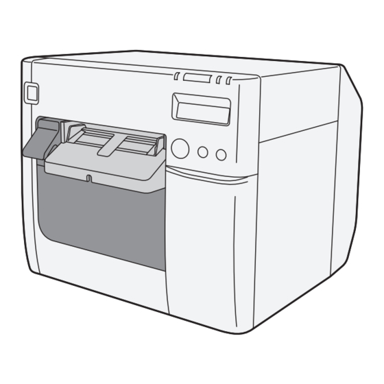
Page 14: Parts Name And Function
Parts Name and Function Front Control panel Power switch cover Power switch Release lever Paper ejection guide Paper ejection table Ink cartridge cover Paper ejection Paper ejection tray Roll paper cover guide lock Control panel Power LED Paper LED Status LED Ink LED CUT button Cleaning button... - Page 15 Chapter 1 Product Overview Back Fanfold paper cover Paper feed guide Fanfold paper guide Connector (lower rear) Status sheet button LAN Connector USB connector Power connector Cable hook Link LED...
-
Page 16: Power Switch
Power Switch Before turning on the printer, be sure to check that the AC adapter is connected to the power supply. CAUTION ❏ When DIP switch 1 is OFF: • Turns the power on after the POWER button has been pressed while the power is OFF. •... -
Page 17: Cut Button
Chapter 1 Product Overview CUT button ❏ If "Media detection settings" is set to "Full-page label/Continuous paper/Transparent full-page label", feeds the paper to the autocutting position for the top of the next page, and performs autocutting. ❏ If "Media detection settings" is set to "Die-cut label (Blackmark)", "Continuous paper (Blackmark)", or "Die-cut label (Gap)/Transparent die-cut label", feeds the paper to the autocutting position according to the black mark or the gap between labels, and performs autocutting. -
Page 18: Status Sheet Button
STATUS SHEET button Press the status sheet button to print the status sheet. If you turn on the power while holding the status sheet button, and continue to hold it for 10 seconds or more, you can return the LAN interface settings to factory default settings. LCD contrast adjustment button Adjusts the LCD contrast. -
Page 19: Connectors
Chapter 1 Product Overview Connectors All cables are connected to the connector on the lower rear of the printer. • Power supply connector: Connects cable of the AC adapter. • USB/LAN Connector: Connects the printer with the host computer via interface. •... -
Page 20: Status/Error Indications
Status/Error Indications The printer status is indicated by a combination of LED lighting/flashing and LCD indication. When an error occurs, you can find out the cause and the remedy from the LED & LCD indication for the error. The LCD display language can be switched with the DIP switches. See "Setting the DIP Switches"... - Page 21 Chapter 1 Product Overview : Lit up : Blinking : Off : No change ## : Error code — Printer Status Status Power Paper M/B READ ERROR Maintenance box read error (*) — — INK LOW Ink cartridge low — —...
-
Page 22: Ink Cartridge And Maintenance Box Status
Ink Cartridge and Maintenance Box Status You can check the status of the printer, the ink cartridges of each color, and the maintenance box from the LCD. Row 1 displays the printer's status Row 2 displays the status of the ink cartridges and maintenance box. -
Page 23: Beeper
Chapter 1 Product Overview Beeper When an error occurs while “Beep Notification Setting at an Error” is enabled, the beeper performs “Sound the beeper on an error” shown in the below table. The beeper continues to beep until all the causes of error are removed. -
Page 24: Auto Nozzle Check System
Auto nozzle check system This product has an “Auto nozzle check system” that detects missing dots. You can select the “Nozzle check mode” depending on level of requirement for missing dots. The following table shows the timing for auto nozzle check for each nozzle check mode (printing operation mode). - Page 25 Chapter 1 Product Overview The following table shows the conditions for permitted missing dots and auto cleaning for each nozzle check mode. Anti-missing No Missing Dot Anti-missing Anti-missing Condition Read Mode Detection Dot Mode Color Mode (Default) Mode No 2 consecutive 1 missing dot or missing dots and Permitted missing dots...
- Page 26 • No Missing Dot Detection Mode The auto nozzle check and the auto head cleaning are not performed. This "Auto nozzle check" system cannot detect 100% of dot missing cases. In cases extremely high reliability and safety is required, Epson recommends the use of font constructed of 3 vertical dots or more in "Anti-missing Dot Mode"...
-
Page 27: Drivers, Utilities
Chapter 1 Product Overview Drivers, Utilities Various utilities are provided to system administrators and application developers. For details on how to get the software, see "Download" on page 178. Drivers Category Name Description Driver for printing from the application using Windows spooler service. -
Page 28: Utilities
Utilities Category Name Description Utility that carries out setting up this printer on one host PC. Deployment Install Navi Performs the initial settings of the host PC and this product in a wizard format. This utility is included in the supplied CD-ROM. Utility for installing multiple printers efficiently. -
Page 29: Setup
Chapter 2 Setup Setup This chapter describes setup and installation of the product and peripherals. Work Flow This chapter consists of the following sections along with the setup flow of the product and peripherals. 1.Checking the Items Included in the Package (page 30) 2.Installing the Printer (page 31) 3.Attaching the Power Switch Cover (page 32) 4.Setting Up the Printer (page 34) -
Page 30: Checking The Items Included In The Package
Checking the Items Included in the Package When using the printer for the first time, check the items included in the package. The items included in the package are as follows: User’ s Manual TM-C3500 Series Dedicated AC adapter AC cable *1 Ink cartridge Maintenance box USB cable... -
Page 31: Installing The Printer
Chapter 2 Setup Installing the Printer Install the printer in an appropriate location with sufficient space around it. Important Notes on Installation 10cm (3.93inch) 10cm (3.93inch) • The printer must be installed horizontally. • Leave enough space in front of the printer for the ink cartridge cover and the roll paper cover to be fully opened. -
Page 32: Attaching The Power Switch Cover
Attaching the Power Switch Cover Attaching the power switch cover prevents accidental pressing of the power switch. Before attaching the power switch cover, set DIP switch 1 to ON. (For details, see “Setting the switches”Setting the DIP Switches on page 48.) The printer power can then be switched by turning the AC supply on and off, and you can also control the printer power with a device such as a distribution board. - Page 33 Chapter 2 Setup To operate the power switch by inserting a long, thin object into a hole Attach the power switch cover after punching the hole in it. The hole cannot be punched in the power switch cover after it is attached to the printer. Punch a hole in the power switch cover by pushing the middle of it with a hard, fine-tipped object.
-
Page 34: Setting Up The Printer
Setting Up the Printer Set up the printer using Install Navi. Install Navi is included in the supplied CD-ROM. Turn on the computer to be connected to the printer. Make sure that the printer is turned off. Be sure to turn the printer off. Set the CD-ROM in the computer, and Launcher automatically starts up.... - Page 35 Chapter 2 Setup Later in the setup procedure, "Media Layout Creation" window appears. When "Media Layout Creation" window appears, if you do not use the roll paper included in the package, you have to create a new media layout. For the procedure to create a new media layout, see Media Layout Creation on page 36....
-
Page 36: Media Layout Creation
Media Layout Creation On "Media Layout Creation" window, select [Yes] and Click [Next]. The following window appears. Select either [Roll Paper] or [Fanfold Paper] and click [Next]. - Page 37 Chapter 2 Setup The following window appears. Select the media to be used and click [Next]. When fanfold paper is selected, you can select [Die-cut label (Gap)], [Die-cut label (Black- mark)], [Continuous paper (Blackmark)], or [Transparent die-cut label (Gap)].
- Page 38 The following window appears. Enter each item and click [Next]. Item Description Media Layout Name Enter any name. Unit Select the unit. Enter the width and length of the media to be used. Media Layout The information to be entered is different depending on the media type selected in Step 3.
- Page 39 Chapter 2 Setup "Confirming the Media Layout” screen appears. The newly set media layout information is displayed. Confirm the settings and click [Next]. "Restarting the Printer” screen appears. Restart the printer to apply the new settings.
-
Page 40: Shutter Adjustment
Shutter Adjustment Turn the printer OFF. Press down the release lever, and pull it to the front to open the roll paper cover. Refer to the shutter adjustment method label on the top of the printer, and open or close the shutters on the platen to match the width of the paper. If the shutter is set incorrectly, paper may be jammed or get dirty. - Page 41 Chapter 2 Setup Close the roll paper cover.
-
Page 42: Ejection Angle Of Printed Paper
Ejection Angle of Printed Paper Make sure paper is ejected straight from the paper ejection guides, as shown in the illustration. If paper is not ejected straight due to such causes as an obstruction, the print result may be distorted. -
Page 43: How To Display The Printer Driver
Chapter 2 Setup How to Display the Printer Driver Open the [Devices and Printers]. For Windows 10: Right click [Start] - [Control Panel] - [Hardware and Sound] - [Devices and Printers]. For Windows 8.1/Windows 8: Select [Control Panel] of Sidebar [Settings] on [Desktop], and click [Hardware and Sound], then [Devices and Printers]. - Page 44 Right-click [EPSON TM-C3500], and click [Printing Preferences]. The printer driver screen is displayed. The barcode printing position is moved based on the amount of margin.
-
Page 45: Registering The Media Layout
Chapter 2 Setup Registering the Media Layout If the paper size to use is not in Media Layout, register the user defined media. The registered layout will be stored in [Favorite Setting] to use from application of users. (For details on how to register the favorite setting, see Favorite Setting on page 83.) Display the printer driver window. -
Page 46: Attaching The Paper Ejection Tray
Attaching the Paper Ejection Tray If you attach the paper ejection tray, you can temporarily store the printed paper in the tray. Follow the steps below to install/adjust the ejection tray. Paper may not stay in the paper ejection tray depending on the paper curl and length. ... - Page 47 Chapter 2 Setup Slide the bottom tray to align it with the paper length. Pull up the lever at the bottom-right of the paper ejection tray to lock it.
-
Page 48: Setting The Dip Switches
Setting the DIP Switches Change the DIP switch settings in the following cases. • When attaching the power switch cover to prevent the power switch from being pressed • When changing the LCD display language • When changing the volume of the buzzer Setting Procedure Follow the steps below to change the DIP switch settings. -
Page 49: Function Of The Dip Switches
Chapter 2 Setup Function of the DIP Switches Factory Function settings Operation of the power switch Reset Power ON/OFF Internal use Fixed to OFF (Do not change) Internal use Fixed to OFF (Do not change) LCD display language settings See the table below Buzzer volume High When attaching the power switch cover to prevent the power switch to be pressed, set DIP... -
Page 50: Setting The Printer Driver
Setting the Printer Driver In addition to the printing preferences, the printer driver also provides the printer settings and various utility functions. • Banding Reduction • TM-C3500 PrinterSetting • Setting for EPSON Status Monitor 3 Banding Reduction You can reduce banding (extraneous lines in printing) to obtain better print quality. This function, however, lowers the print speed. - Page 51 Chapter 2 Setup "Advanced" screen appears. Check [Banding Reduction], and click [Close]. The screen returns to "General" window. Click [OK].
-
Page 52: Tm-C3500 Printersetting
TM-C3500 PrinterSetting TM-C3500 PrinterSetting is used to change various printer settings. - Page 53 Chapter 2 Setup From TM-C3500 PrinterSetting, you can change the following printer settings: Item Description Media source settings Media source settings Media detection settings General Nozzle Check Mode Printer Operation Settings Paper Loading Settings Beep Notification Setting at an Error ...
-
Page 54: Setting Epson Status Monitor 3
Setting EPSON Status Monitor 3 When EPSON Status Monitor 3 is used, the paper type and the ink level are displayed on a pop-up window when printing. In addition, when a fatal error occurs, an error window is displayed. [Not use] is set by default setting; however, if a fatal error occurs, an error window can be displayed. Use/Not use EPSON Status Monitor 3 [Not use EPSON Status Monitor 3] is set by default setting. - Page 55 Chapter 2 Setup Follow the steps below to change to [Use EPSON Status Monitor 3]. Turn the printer ON. Display the printer driver window. (See How to Display the Printer Driver on page 43.) Select [Driver Utilities] tab and click [Driver Preferences] under [Driver Prefer- ences].
- Page 56 Use EPSON Status Monitor 3 When [Use EPSON Status Monitor 3] is set, the following operations will be performed: • When printing, a window automatically appears, allowing you to check the printer status and the ink level. • Error information is displayed when an error occurs during printing. The EPSON Status Monitor 3 will not be activated if an error occurs when not printing.
- Page 57 Chapter 2 Setup • The following items can be set in [Monitoring preferences]. Selecting error indications: (See Error notification setting for [Not use EPSON Status Monitor 3] on page 58.) Displaying the [EPSON Status Monitor 3] icon on the task bar: (See Displaying the icon on page 60.)
- Page 58 Error notification setting for [Not use EPSON Status Monitor 3] Follow the steps below to set error notification for [Not use EPSON Status Monitor 3]. Turn the printer on. Display the printer driver window. (See How to Display the Printer Driver on page 43.) Select [Driver Utilities] tab and click [Driver Preferences].
- Page 59 Chapter 2 Setup Error notification setting for [Use EPSON Status Monitor 3] Follow the steps below to set error notification for [Use EPSON Status Monitor 3]. Turn the printer ON. Display the printer driver window. (See How to Display the Printer Driver on page 43.) Select [Driver Utilities] tab and click [Monitoring Preferences].
- Page 60 Displaying the icon Keeps icon on the task tray so that user can check as needed. The icon is not displayed when default setting. Follow the steps below to display the icon. Turn the printer ON. Display the printer driver window. (See How to Display the Printer Driver on page 43.)
-
Page 61: Handling
Chapter 3 Handling Handling This chapter describes basic handling of the printer. Replacing the Ink Cartridge When the ink ends, the INK LED lights. Follow the steps below to replace the ink cartridge. Turn the power on and make sure that the INK LED lights. Pull down the ink cartridge cover to the front to open it. - Page 62 With the label facing upwards, insert the new ink cartridge, and push it in slowly until it clicks into place. Close the ink cartridge cover. When the ink cartridge replacement is completed, the INK LED turns off, and printing can be performed. Cautions on using ink cartridges ❏...
- Page 63 Chapter 3 Handling ❏ Do not allow foreign objects to fall into the cartridge installation section. Doing so may cause printer malfunction. ❏ When ink is charged for the first time (right after purchase), ink is consumed for filling the print head nozzle (ink discharge holes) to get ready for printing.
-
Page 64: Replacing Maintenance Box
Replacing Maintenance Box Do not dismantle the Maintenance box. Do not touch the IC chip on the cartridge. Keep out of reach of children, and do not drink. Do not reuse a maintenance box which was removed and detached for a long period. ... - Page 65 Chapter 3 Handling Put the maintenance box into the plastic bag for disposal of used mainte- nance box. Slowly insert the new maintenance box. Close the maintenance box cover. After replacing the maintenance box, we recommend that you clean the platen. (See the "Cleaning the platen"...
-
Page 66: Replacing Roll Paper With Fanfold Paper
Replacing Roll Paper with Fanfold Paper Follow the steps below to replace the roll paper with fanfold paper. Press down the release lever, and pull it to the front to open the roll paper cover. Remove the used roll paper. Turn the printer ON. - Page 67 Chapter 3 Handling From TM-C3500 PrinterSetting, specify the media source and the media detection method. Then, click [Apply Settings]. After setting [Media source], set [Media detection settings]. Item Description Media source Select [Fanfold paper]. Select the media type. Die-cut label (Blackmark) Media detection settings ...
- Page 68 The completion window appears. Click [OK]. On the printer driver window, select [General] tab. Specify the media set- tings and click [OK]. Item Description Media Type Select the media type. Print Quality Select the print quality. Print Settings Select the media layout. If the media layout to be used is not included in the Media Layout list, create a new layout.
- Page 69 Chapter 3 Handling Open the fanfold paper cover and take out the paper feed guide. Pull the release lever to the front to open the roll paper cover. Insert the paper feed guide for fanfold paper into the groove inside the roll paper cover to install it.
- Page 70 Refer to the shutter adjustment method label on the top of the printer, and open or close the shutters on the platen to match the width of the roll paper. If the shutter is set incorrectly, paper may be jammed or get dirty. Close Open Paper/backing width (mm)
- Page 71 Chapter 3 Handling Release the lock of the paper ejection guide with a fine-tipped tool. Slide the paper ejection guide to the very left end, and lock it. Open the cover at the back of the printer, and unlock the fanfold paper guide.
- Page 72 Adjust the fanfold paper guide to the fanfold paper width. Lock the fanfold paper guide. Turn the printer ON.
- Page 73 Chapter 3 Handling Insert the fanfold paper into the paper slot, facing the print surface upward. Insert the paper until it is pulled into inside the printer (approximately 100 mm {3.94"}). The printer detects the edge of the fanfold paper, pulls it inside, and then starts feeding it to the print starting position.
- Page 74 Close the fanfold paper cover. To prevent liquid and dust from getting into the printer, keep the fanfold paper cover closed when using the printer. To prevent paper jams from occurring, insert fanfold paper into the fanfold paper slot on the back of the printer with the roll paper cover closed.
-
Page 75: Replacing Fanfold Paper With Roll Paper
Chapter 3 Handling Replacing Fanfold Paper with Roll Paper Follow the steps below to replace the fanfold paper with roll paper. Open the fanfold paper cover at the back of the printer. Remove the used fanfold paper. Turn the printer ON. Display the printer driver window. - Page 76 From TM-C3500 PrinterSetting, specify the media source and the media detection method. Then, click [Apply Settings]. After setting [Media source], set [Media detection settings]. Item Description Media source Select [Roll paper]. Select the media type. Full-page label, Continuous paper, Transparent full-page label ...
- Page 77 Chapter 3 Handling The confirmation window appears. Click [Yes] to send the settings to the printer. The following window appears. Click [OK]. The completion window appears. Click [OK].
- Page 78 On the printer driver window, select [General] tab. Specify the media set- tings and click [OK]. Item Description Media Type Select the media type. Print Quality Select the print quality. Select the media layout. Print Settings If the media layout to be used is not included in the Media Layout list, create a new layout.
- Page 79 Chapter 3 Handling Press down the release lever, and pull it to the front to open the roll paper cover. Remove the paper feed guide for fanfold paper. Unlock the roll paper guide.
- Page 80 Move the left paper guide toward the direction of the arrow in the illustra- tion below, and insert the roll paper all the way in with the print surface fac- ing upward. Lock the roll paper guide.
- Page 81 Chapter 3 Handling Refer to the shutter adjustment method label on the top of the printer, and open or close the shutters on the platen to match the width of the roll paper. If the shutter is set incorrectly, paper may be jammed or get dirty. Close Open Paper/backing width (mm)
- Page 82 Adjust the paper ejection guide to the roll paper width. Lock the paper ejection guide and close the roll paper cover. Turn the printer ON. After this, the printer feeds the paper automatically to remove any slack in the roll paper. Confirm that the LCD displays an "R".
-
Page 83: Setting The Printer Driver
Chapter 3 Handling Setting the Printer Driver Favorite Setting [Favorite Setting] is the function to administer print setting of the printer driver into one. The setting from [General] and [Options] tab such as Media Type, Media Layout (including User Defined Media) are included. [General] tab Favorite Setting [Options] tab... - Page 84 Features • When printing from application, the print setting registered on [Favorite Setting] can be selected as default setting. It is recommended to register the setting in favorite setting after executing print setting by clicking [Save As Favorite Setting]. • A number of setting can be registered on [Favorite Setting]. For example, if the print setting is registered on [Favorite Setting] for each document, the print set- ting can be completed by changing [Favorite Setting] when the document is changed.
- Page 85 Chapter 3 Handling Registering print setting on [Favorite Setting] Set the printer driver depending on paper to print. Set settings on [General] and [Options] tab. Select from Media Layout when using User Defined Media. Click [Save As Favorite Setting] to display [Save/Delete Favorite Setting]. The current setting will be displayed on the list of the right side.
-
Page 86: Information For User Definition
[Favorite Setting] includes the following setting. • Default Settings: The default setting when installing the printer driver. • Current Settings: The contents set on [General] and [Options] tab. These contents are displayed in the current settings on [Current Setting] and [Save/Delete Favorite Setting] window. •... -
Page 87: Exporting/Importing Printer Driver Settings
Chapter 3 Handling Exporting/Importing Printer Driver Settings You can export the printing references, favorite setting, user-defined information (paper layout, barcode) and printer driver operation settings into a BSF file (extension of ".BSF"). You can also import the settings from a BSF file to set up the printer driver. Export Settings Follow the steps below to export the settings. - Page 88 "Import/Export Settings" window appears. Click [Export Settings]. The window to save a file appears. Specify a name and save the BSF file. The process completion window appears. Click [OK]. To the BSF file, the print settings in "favorite setting" defined by the user are applied. The print settings in "Current settings"...
-
Page 89: Barcode Printing
Chapter 3 Handling Barcode Printing The printer driver has the built-in barcode font. Barcode printing is available if the barcode is not created on the application side. Setting the barcode font Barcode print settings can be changed on [Barcode and 2D Symbol] on [Driver Utilities] tab. - Page 90 Change settings of the following. • Display: Select [Barcodes]. • Font Name: Input an arbitrary character string. ASCII characters only. • Type: Select a barcode type from the following. The displayed items are changed accordingly. UPC-A UPC-E JAN13(EAN) JAN8(EAN) CODE39 Codabar CODE93 CODE128...
- Page 91 Chapter 3 Handling • Module: Sets the thin element width in dots. Upper Line: Minimum Mod- ule [by 360 dpi] Lower Line: Minimum Element Graphic resolu- Adjust Ratio tions Print direc- Category (Horizontal x tion *1 ANSI ANSI ANSI Width *2 vertical) (dpi) Grade Grade...
- Page 92 By the combination of the specific paper type and the Symbol, the following conditions are available. Wristband & CODE128 : Element = 5 dots (D-grade) Wristband & Codabar : Element = 5 dots, Element ratio = 2.5 (C-grade) • Bar Height: Sets the element height with dots.
- Page 93 Chapter 3 Handling Specifying the barcode data Specify the barcode data by referring to the following descriptions. About the composite symbol: The composite component type is selected automatically depending on the digit number of the data. (CC-C is selected only when GS1-128 is set.) Composite Component Type Encodable Digit Number CC-A...
- Page 94 JAN13(EAN) ❏ Normal • Specify the data of 11 to 12 digits. • For data of 12 digits, a check digit is automatically added. • For data of 13 digits, the 13th digit is regarded as a check digit, but not proved. ❏...
- Page 95 Chapter 3 Handling CODE93 ❏ Specify the data of 1 to 255 digits. ❏ A start code, 2 check digits, stop code is automatically added. ❏ A character () that indicates a start code is printed for the head of the HRI character. ❏...
- Page 96 CODE128 ❏ Specify the data of 2 to 255 digits. ❏ Specify either one of the code selection characters (CODE A, CODE B, CODE C) as a start code of the first 2 digits. ❏ A special character is indicated by combining ‘{‘ and the next character. ❏...
- Page 97 Chapter 3 Handling GS1-128 ❏ Specify the data of 2 to 255 digits. ❏ ‘()’ is the delimiter for the application identifiers. (printed as the HRI character, but not encoded.) ❏ The start codes (CODE A, CODE B, CODE C) and the stop code are added automatically. ❏...
- Page 98 GS1-128M ❏ Specify the data of 38 to 66 digits. ❏ ‘()’ is the delimiter for the application identifiers. (printed as the HRI character, but not encoded.) ❏ The start codes (CODE A, CODE B, CODE C) and the stop code are added automatically. ❏...
- Page 99 Chapter 3 Handling GS1 DataBar Omnidirectional/GS1 DataBar Truncated/GS1 DataBar Limited ❏ The first application identifier ‘01’ is not included in the data. ❏ When printing the HRI characters, the first application identifier ‘01’ is printed as ‘(01)’ before the packing identification code. ❏...
- Page 100 GS1 DataBar Expanded ❏ Specify the data of 2 to 255 digits. ❏ ‘()’ is the delimiter for the application identifiers. (printed as the HRI character, but not encoded.) ❏ Be sure to include all the application identifiers in the data. ❏...
-
Page 101: 2D Symbol Font Settings
Chapter 3 Handling 2D Symbol Font Settings The printer driver has the built-in 2D symbol font. 2D symbol printing is available if the 2D symbol is not created on the application side. Setting the 2D Symbol font 2D symbol printing settings can be changed on [Barcode and 2D Symbol] on [Driver Utilities] tab. - Page 102 Change settings of the following. • Display: Select [2D Symbols]. • Font Name: Input an arbitrary character string. ASCII characters only. • Type: Select a 2D symbol type. The displayed items are changed accordingly. • Rotation Settings: Select a setting when printing the 2D symbol rotated by the specified rate.
- Page 103 Chapter 3 Handling Make settings of the following items according to the selected [Type]. • PDF417 Module Width: Makes settings of the module width for PDF417. Module Height: Makes settings of the module height for PDF417 by the ratio to the module width. Column: Input the number of columns for PDF417.
- Page 104 • DataMatrix(Rectangle) Cell Size: Makes settings of the cell (module) size for DataMatrix. Number of Vertical Cells: Specify the number of cells for DataMatrix in the vertical direction. Number of Horizontal Cells: Specify the number of cells for DataMatrix in the horizontal direction. [Minimize]: Optimize the minimum number of cells automatically....
- Page 105 Chapter 3 Handling • Recommended value for setting the barcode/2D symbol font (2D symbol of matrix type) (AztecCode, QRCode) Minimum Cell Size Graphic reso- [by 360 dpi] lutions Category Print Status (*1) ANSI ANSI ANSI (Horizontal x Grade D Grade C Grade B or vertical) (dpi) or higher...
- Page 106 Specifying the 2D symbol data See the following description to specify the 2D symbol data. For the composite symbol and the HRI character, see "Specifying the barcode data" on page PDF417 ❏ Calculated automatically when the digit number and the line number are 0. ❏...
- Page 107 Chapter 3 Handling AztecCode ❏ Supports the full range mode and the compact mode. DataMatrix ❏ Supports the ECC200 versions - square and rectangular. Printing method Specify the selected 2D symbol font, specified point and language to the printing data, and print it. The font size of the 2D symbol can not be changed by [Specified Point] value.
-
Page 108: Barcode And 2D Symbol Font Printing On .Net Environment
Barcode and 2D Symbol Font Printing on .NET Environment Since .NET Framework supports only True Type font and Open Type font, the barcode and 2D symbol font which are registered in the printer driver can not be printed from the application. Therefore, True Type font is replaced with barcode and 2D symbol font by using font replacement function of the printer driver. - Page 109 Chapter 3 Handling Printing barcode and 2D symbol Sets specified number of point, language of the replaced True Type font by barcode and 2D symbol font to the print data. The number of point for barcode and 2D symbol is specified, check it from [Barcode and 2D Symbol] on [Driver Utilities].
-
Page 110: Print Preview
Print Preview If this function is checked, the print preview window is displayed when printing is performed from an application, allowing you to check the print result image before printing. Displays the print preview before printing if this check box is turned on. To improve 2D symbol scanning accuracy, we recommend no paper feed during 2D symbol printing. -
Page 111: Settings For Paper Handling After Print
Chapter 3 Handling Settings For Paper Handling After Print Follow the steps below to set whether to enable autocut after printing and paper feed settings. Display the printer driver window. (See "How to Display the Printer Driver" on page 43.) On [General] tab, set [Settings For Paper Handling After Print]. - Page 112 Item Description After printing, the paper is fed to the position where autocut- ting is possible and is automatically cut on a page-by-page After Every Page basis. When resuming printing, the paper is fed in the reverse direction to the printing position and then printing resumes. After printing, the paper is fed to the position where autocut- Only After Last ting is possible and only the last page is automatically cut.
-
Page 113: Beeper
Chapter 3 Handling Beeper Follow the steps below to set whether to sound the beeper after printing and the timing to sound the beeper. Display the printer driver window. (See "How to Display the Printer Driver" on page 43.) On [General] tab, select [Notification]. Item Description None... -
Page 114: Setting The Printer
Setting the Printer Media detection settings This product can perform the following four types of [Media detection settings]. The aforementioned [Media source settings] and the [Media detection settings] are related as below table. ❏ Full-page label/Continuous paper/Transparent full-page label Detects paper presence only and does not adjust the paper position. ❏... - Page 115 Chapter 3 Handling Setting procedure Follow the steps below to set the Media detection settings. Remove the paper. For roll paper: See step 1 in "Replacing Roll Paper with Fanfold Paper" on page For fanfold paper: See steps1 to 2 in "Replacing Fanfold Paper with Roll Paper"...
- Page 116 The "Media settings" screen is displayed. Set [Media detection settings]. Click [Apply Settings]. When fanfold paper is selected, the gap may not be detected depending on the paper you are using. If this happens, perform [Adjust the Label Gap Detection Sensor]. For details, see "Sen- sor Adjustment"...
-
Page 117: Nozzle Check Mode Settings
Chapter 3 Handling Nozzle Check Mode Settings The following modes are available for the printing operation mode setting. (The mode is set to [Anti- missing read mode] by default. If you use the default setting, there is no need to change the settings.) •... - Page 118 "Printer Operation Settings" window appears. Set [Nozzle Check Mode] under [Nozzle Check Mode Settings]. Then, click [Apply Settings]. The confirmation window appears. Click [Yes] to send the settings to the printer.
-
Page 119: Paper Loading Settings
Chapter 3 Handling Paper Loading Settings Follow the steps below to specify the settings for paper loading at power-on/paper cover close. The following types are available for the settings for paper loading at power-on/paper cover close. (The type is set to [Paper feed for positioning (With cutting)] by default. If you use the default setting, there is no need to change the settings.) Paper loading at power-on Settings... - Page 120 Paper feed for positioning (Without cutting) Settings Description Paper loading settings: Die-cut label (Blackmark), Continuous paper (Blackmark), Die-cut label (Gap)/Transparent die-cut label Paper is loaded based on the upper end of black mark/label detected by the black mark detector or label detector. After paper feed is finished, autocut is per- Paper feed for formed and the printer enters the standby status.
- Page 121 Chapter 3 Handling Turn the printer on. Display the printer driver window. (See "How to Display the Printer Driver" on page 43.) Select [Printer Utilities] tab and click [Printer Setting Utility] under [Printer Pref- erences]. TM-C3500 PrinterSetting window appears. Select [General]-[Printer Opera- tion Settings].
-
Page 122: Notification Settings
Notification Settings Sets following notification setting. • Beep Notification Setting at an Error Selects beep notification (sounds buzzer or not) when error occurs. (Default setting is [Beep]. The user does not need to change when using with default setting.) • LED Notification Setting at Ink Low Selects LED notification (lights LED or not) when ink level is low. - Page 123 Chapter 3 Handling "Notification Settings" window appears. Specify each item. Then, click [Apply Settings]. The confirmation window appears. Click [Yes] to send the settings to the printer.
-
Page 124: Panel Button Settings
Panel Button Settings Enable/disable the panel buttons of this printer. Operation Caused Panel Button Settings by Panel Button Feed Button Paper feed Enable / Disable Cut Button Paper cut Enable / Disable Enable(Also Enabled During Printing)/ Cleaning Button Head cleaning Ena ble(Disa bled Dur ing Pr inting) / Disable Follow the steps below to make the setting. - Page 125 Chapter 3 Handling "Panel Button Setting" window appears. Specify each item. Then, click [Apply Settings]. The confirmation window appears. Click [Yes] to send the settings to the printer.
-
Page 126: Operating Time Settings
Operating Time Settings Allows you to specify the following: Settings Description Allows you to specify the time before stopping the platen vacuum fan after print- Platen Vacuum ing completion. Operation Pause The time may be extended up to 12 hours in accordance with the way the printer Time Settings is used. - Page 127 Chapter 3 Handling Turn the printer on. Display the printer driver window. (See "How to Display the Printer Driver" on page 43.) Select [Printer Utilities] tab and click [Printer Setting Utility] under [Printer Pref- erences]. TM-C3500 PrinterSetting window appears. Select [Advanced Settings]- [Operating Time Settings].
-
Page 128: Paper Feed Adjustment
Paper Feed Adjustment Allows you to specify the following: Settings Description Cut Position Adjust the cut position. The unit is 1/180 inch. You can make adjustments in the Adjustment range of -63 to 63. Print Start Position Adjust the print start position (vertical direction). The unit is 1/180 inch. You can Adjustment make adjustments in the range of -63 to 63. - Page 129 Chapter 3 Handling Adjustment Method Turn the printer on. Display the printer driver window. (See "How to Display the Printer Driver" on page 43.) Select [Printer Utilities] tab and click [Printer Setting Utility] under [Printer Pref- erences]. TM-C3500 PrinterSetting window appears. Select [Printer Adjustment]- [Paper Feed Adjustment].
- Page 130 Cut Position Adjustment The paper feed pitch is adjusted as described below depending on the [Media detection settings]. Media detec- Description tion settings Specifying a positive value moves the cut position closer to the reference position (print start position). ...
- Page 131 Chapter 3 Handling Media detec- Description tion settings Specifying a positive value moves the cut position closer to the reference position (print start position). Specifying a negative value moves the cut position away from the reference position (print start position). Backing paper Print reference (Print start position)
- Page 132 Media detec- Description tion settings Specifying a positive value moves the cut position closer to the reference position (print start position). Specifying a negative value moves the cut position away from the reference position (print start position). Backing paper Print reference (Print start position) Print result...
- Page 133 Chapter 3 Handling Print Start Position Adjustment (Vertical Direction) The paper feed pitch is adjusted as described below depending on the [Media detection settings]. Media detec- Description tion settings Specifying a positive value moves the print start position and cut position away from the reference position (top of label).
- Page 134 Media detec- Description tion settings Specifying a positive value moves the print start position and cut position away from the reference position (blackmark position). Specifying a negative value moves the print start position and cut position closer to the reference position (blackmark position). Backing paper Print reference (Black mark position)
-
Page 135: Sensor Adjustment
Chapter 3 Handling Sensor Adjustment The threshold for the sensor can be adjusted when the sensor does not detect the label gap and black mark for the paper to be used. Follow the steps below to make adjustment. Load the paper to the printer. Turn the printer on. -
Page 136: Print Head Alignment
Print Head Alignment Adjust the print head alignment (gap) when vertical and horizontal lines appear misaligned or printed characters are blurred. The banding adjustment may not completely solve gaps between lines or prints over previous lines. Turn the printer on. Display the printer driver window. -
Page 137: Network Interface
Chapter 3 Handling Network Interface The LAN interface information for this printer is as shown below. The network setting can be checked by printing the status sheet. See "Status Sheet Printing (LAN interface model only)" on page 161. Factory settings The factory settings for this printer are as follows: Item Factory settings... -
Page 138: Troubleshooting
Troubleshooting Trouble Recovery Method Trouble status (Image/Illustration) No.1 No.2 No.3 No.4... - Page 139 Chapter 3 Handling Image/ Trouble Description Recovery method Illustra- tion The LCD displays the "Error Recovery Method" on An error has occurred content of the error. page 151. Perform nozzle check and check whether print nozzles are clogged. If the print nozzles are clogged, per- form head cleaning.
- Page 140 Image/ Trouble Description Recovery method Illustra- tion Adjust the alignment of paper feed. On the [Printer Utilities] tab, click [Printer Setting Utility]. As the paper feeding When the PrinterSetting screen is dis- amount varies depend- played, click [Printer Adjustment] - ing on the paper being [Print Head Alignment], and perform No.
- Page 141 Chapter 3 Handling Image/ Trouble Description Recovery method Illustra- tion If you have moved the Perform manual head cleaning until printer after the initial there are no more mixed colors. Print results look differ- ink charge, specified ent from what was colors may not be pro- No.
- Page 142 Image/ Trouble Description Recovery method Illustra- tion When the shutters on the platen on the outer side of the paper are set to open, air current may cause printing The shutters on the trouble; outer edges of the print platen on the outer side result may become blurry.
- Page 143 Chapter 3 Handling Image/ Trouble Description Recovery method Illustra- tion The width of the bars has to be cor- rected to print barcodes correctly. Use the barcode and 2D symbol fonts that are installed with the printer driver, or a barcode genera- tor application to correct the width of bars.
- Page 144 Image/ Trouble Description Recovery method Illustra- tion When the paper width and the set- tings for the shutters on the platen do not match, paper may be lifted; the The paper width and print head may touch and smudge the settings for the shut- the paper.
- Page 145 Chapter 3 Handling Image/ Trouble Description Recovery method Illustra- tion For thermal label printers, the label size is generally considered as “print- able area”, however for TM-C3400, it is considered as “label size” - “mar- gins” = printable area. Therefore, TM-C3400 comes with the Auto Fit Page function so that the same paper layout can be used even when the printable area is...
- Page 146 Image/ Trouble Description Recovery method Illustra- tion To perform borderless printing, use the label that is cut in half and still has edge cutoffs. Specify a printable area that is larger than the actual I want to perform bor- label size and print. derless printing "Setting the label size and paper layout for borderless printing"...
- Page 147 Chapter 3 Handling Image/ Trouble Description Recovery method Illustra- tion Check the paper you are using and The paper you are using the printer’s [Media detection set- does not match the tings]. [Media detection set- "Media detection settings" on tings]. page 114.
- Page 148 Image/ Trouble Description Recovery method Illustra- tion Check the paper you are using and The paper you are using the printer’s [Media detection set- does not match the tings]. [Media detection set- "Media detection settings" on tings]. page 114. The label gap may not be detected. Infrared light is used to detect the label gap;...
- Page 149 Chapter 3 Handling Image/ Trouble Description Recovery method Illustra- tion Check the paper you are using and The paper you are using the printer’s [Media detection set- does not match the tings]. [Media detection set- "Media detection settings" on tings]. page 114.
- Page 150 Image/ Trouble Description Recovery method Illustra- tion See “TM-C3400/C3500 Series Design Manual for Media Take-up Unit”. On the [Printer Utilities] tab, select [Printer Setting Utility]. (2) Select [Option] and [Enable Selection of Large-diameter roll paper (Use the Rear Feed Slot)] in I do not know how to [Media Source Settings Option].
-
Page 151: Error Recovery Method
Chapter 3 Handling Error Recovery Method The following table shows the error recovery methods. LCD display Description Recovery method Set the type of paper specified for "Media The type of the paper set in the printer is different from the speci- detection settings". - Page 152 LCD display Description Recovery method An ink cartridge is not loaded. Load an ink cartridge with sufficient ink left. NO INK CARTRIDGE "Replacing the Ink Cartridge" on page Remove the ink cartridge. Load the ink The ink cartridge information could not be read.
- Page 153 Chapter 3 Handling LCD display Description Recovery method Paper jam 1. Turn the printer off. Poor autocutter operation 2. Open the roll paper cover. Irregular ambient temperature 3. Check the paper path for a paper jam. If PRINTER ERROR ## jammed paper is found, remove it com- Malfunction ##: 20 to 54, 64 to 75,...
-
Page 154: When The Print Result Is Faint Or White Lines Or Black Lines Are Printed
When the print result is faint or white lines or black lines are printed Follow the steps below to clear the problem efficiently. For roll paper: C h e c k i f t h e p a p e r i s loaded correctly. - Page 155 Chapter 3 Handling Sel ect [Banding Reduc- When the paper type is set to other than [Plain] or [Plain Label], select tion]. [Banding Reduction] to reduce black lines or white lines when printing. On the printer driver's [General] tab, select [Advanced] from [Print Settings], click [Advanced...], and then select [Banding Reduction].
-
Page 156: When The Printer Is Not Found Even If Epsonnet Config Is Started
When the printer is not found even if EpsonNet Config is started When the printer is not found even if EpsonNet Config is started, follow the steps below. Restart EpsonNet Config. Exit EpsonNet Config without pressing the [Refresh] button and then start it again. Wait 30 seconds. -
Page 157: Help For Epson Printers
Chapter 3 Handling HELP for EPSON Printers You can view the help for the driver to handle errors. Follow the steps below to display the troubleshooting for the driver's LCD display. Display the printer driver window. (See "How to Display the Printer Driver" on page 43.) Click [Help] at the bottom-right of the window. - Page 158 "Error Recovery to LCD Display" appears.
-
Page 159: Setting Check Modes
Chapter 3 Handling Setting Check Modes Besides the ordinary print mode, the printer has the self-test mode and allows you to print the status sheet to check the various settings of the printer. Self-test Mode Printing errors such as dot missing can be checked on self-test mode. In addition, the firmware version, Post-Printing Verification Settings, and Media detection settings can be checked. - Page 160 Status Specification Nozzle check mode Aamd Anti-missing Dot Mode Aamr Anti-missing Read Mode Aamc Anti-missing Color Mode Anod No Missing Dot Detection Mode Media detection settings Cnod Full-page label/Continuous paper/Transparent full- page label Cbmd Die-cut label (Blackmark) Cbmc Continuous paper (Blackmark) Cgap Die-cut label (Gap)/Transparent die-cut label...
-
Page 161: Status Sheet Printing (Lan Interface Model Only)
Chapter 3 Handling Status Sheet Printing (LAN interface model only) Network setting can be checked by printing the status sheet for the LAN interface model. Following status sheet is printed when pressing the status sheet button on the rear of the printer. The network setting can be reset to the default value by turning on the printer while pressing the status sheet button and holding the button down for 20 seconds or more. -
Page 162: Reset
Reset The printer resets in the following cases (called "hardware reset"): ❏ When the printer is initialized with the RESET button ❏ After the printer's firmware is updated Cleaning the Printer Cleaning the platen When replacing the maintenance box, use the non-woven cloth and cotton swabs included in the maintenance box and clean the platen in the following procedure. - Page 163 Chapter 3 Handling Use the non-woven cloth included with the maintenance box to wipe off stains on the platen. Your hands or paper may be stained by the ink on the platen. If the three holes in the platen are clogged with ink, ink stains may occur inside the printer.
-
Page 164: Cleaning The Autocutter
Cleaning the Autocutter Adhesive from labels may stick to the fixed blade of the autocutter, which may prevent the autocutter from cutting paper cleanly. If this happens, follow the steps below to clean the autocutter. Turn off the printer, and unplug the AC cable from the outlet. Open the roll paper cover and remove the paper. -
Page 165: Media Arrangement
Chapter 3 Handling Media arrangement Media arrangement when feeding media for printing from the first sheet Roll paper This can be used with the following media forms. • Continuous paper (Blackmark) • Die-cut label (Blackmark) • Die-cut label (Gap) • Transparent die-cut label Loading Paper When feeding paper, bring the edge of the roll paper between the autocutting position and the edge of the paper ejection table, then close the roll paper cover. - Page 166 Fanfold Paper The following media is supported: • Continuous paper (Blackmark) • Die-cut label (Blackmark) Method for arranging the media • Continuous paper (Blackmark) Place the edge of the first black mark in a position 25 mm {0.98”} or more from the edge of the paper, and do not place a black mark before there.
-
Page 167: Media Arrangement For Printing On The Last Sheet
Chapter 3 Handling Media arrangement for printing on the last sheet Roll paper The following media is supported: • Continuous paper (Blackmark) • Die-cut label (Blackmark) • Die-cut label (Gap) • Transparent die-cut label Premise • The starting part of the paper roll and the roll core are not glued or taped down. •... - Page 168 Method for arranging the media • Continuous paper (Blackmark), and Die-cut label (Blackmark) Ensure a margin of 107.5 mm {4.32"} or more from the rear edge of the last ticket or label to be printed, and for labels, leave only the backing. Also, behind the last ticket or label to be printed, place a black mark [A in the figure] at the same interval up until that point [L in the figure], leave a gap of 5 ±...
- Page 169 Chapter 3 Handling Fanfold paper The following media is supported: • Continuous paper (Blackmark) • Die-cut label (Blackmark) Premise • Moving to the peel position as post-printing processing is not selected. • For Continuous paper (Blackmark) and Die-cut label (Blackmark), Enable "Notification setting at media size error".
-
Page 170: Setting The Label Size And Paper Layout For Borderless Printing
Setting the label size and paper layout for border- less printing This section explains the approaches for borderless printing and how to set the paper size and layout. Apply the settings when designing the label paper, making the driver settings, and setting the data size on the application. - Page 171 Chapter 3 Handling 70 mm (Backing paper width) 66.0 mm (Label width including fringes) 63.0 mm (Print area width) 60.0 mm (Label width) Paper feeding direction 1.5 mm 1.5 mm 1.5 mm 1.5 mm 2.0 mm 2.0 mm Print area specified in [User Defined Media Layout] in the printer driver Printing data position (Top: 63.0 ×...
-
Page 172: How To Make Media Settings
How to Make Media Settings Depending on the paper you are using, the print result may be faint or white lines or black lines may be printed. Follow the steps below to make paper settings. Load the paper and turn on the printer. Display the printer driver window. -
Page 173: Application Development Information
Chapter 4 Application Development Information Application Development Information This chapter describes how to control the printer and gives information useful for printer application development. Printer Control Method The control method for the printer differs depending on the use environment. Application specifications Control method Page Printing using the Epson printer driver installed... -
Page 174: Using Epson Inkjet Label Printer Sdk
Using Epson Inkjet Label Printer SDK The necessary environments to print with a customer's application using an Epson's printer driver are provided as SDK. The following items are included. Items Description EPSON Inkjet Label Printer SDK This explains the configuration overview of the Inkjet Label User's Guide Printer SDK, necessary functions to control Epson Inkjet label printers from an application, and settings that need to be per-... -
Page 175: Utilities And Manuals
Chapter 4 Application Development Information Utilities and Manuals The several kinds of utilities and manuals other than the printer driver are available for this printer. Name Manual Printer Driver TM-C3500 Series Technical Reference Guide EPSON Inkjet Label Printer SDK EPSON Inkjet Label Printer SDK User's Guide InstallNavi None EpsonNet Config... - Page 176 USB Printer Class Device Replacement Service This is a resident service on the computer. When the TM-C3500 is replaced for service or other reason, this detects the printer connection and automatically changes the output printer of the printer driver. This allows the printer to be replaced without changing settings in the application. (The printer is not replaced if a port is specified for the application output destination.
- Page 177 Chapter 4 Application Development Information Restrictions in USB Printer Class Device Replacement Service After the printer is replaced, the green check mark indicating [default printer] in "Devices and Printers" window may be shown on the previous printer that was applied before replacement. Or the check mark may not appear.
-
Page 178: Download
Download Drivers, utilities, and manuals can be downloaded from one of the following URLs. For customers in North America, go to the following web site: http://www.epsonexpert.com/ and follow the on-screen instructions. For customers in other countries, go to the following web site: https://download.epson-biz.com/?service=pos... -
Page 179: Maintenance
Chapter 5 Maintenance Maintenance This chapter describes the efficient management method of the printers and printer drivers by using utilities, targeted at the system administrators operating multiple TM-C3500 units and client computers. • Setting up printer before installation (media type, IP address) •... - Page 180 • Creating a package to install/set up the printer driver on a client computer. The printer driver setup can be completed only by executing from each client computer. Necessary information for an administrator of the printer (page 181) • Utility (page 181) •...
-
Page 181: Necessary Information For An Administrator Of The Printer
Chapter 5 Maintenance Necessary Information for an Administrator of the Printer This section describes the necessary information particularly for the administrator of the printer. Utility The utilities are provided to set up multiple printers and client computers. Setting During system configuration During maintenance Printer setting EPSON Deployment Tool... -
Page 182: Setting The Printer
Setting the Printer You can set the following items before charging ink in the printer: • Media source settings • Media detection settings • Network settings such as IP address You can set the media settings and IP address settings which are minimally necessary to use a printer before ink charging. -
Page 183: Setting The Printer Driver
Chapter 5 Maintenance Setting the Printer Driver The printer driver settings can be output to a configuration file (*.bsf) or imported from another configuration file. When using such operations, note the following point: The BSF file is used also when creating a package (driver installation package/driver setting change package) for client computer setup. - Page 184 • Barcode Font List • Barcode Font Replacement List...
-
Page 185: System Configuration
Chapter 5 Maintenance System Configuration Installing the Printer Set up a printer using Epson Printer Deployment of EPSON Deployment Tool and install the printer in the specified location. 1. Creating a printer settings list Create a settings list of the printers to be installed and the settings for the following items that can be set before ink charging. -
Page 186: Distributing The Printer Driver
Distributing the Printer Driver Create a driver installation package and distribute it to each client computer. The driver installation package is used to automatically install the printer driver and set up the printer driver. The package is created using Epson Driver Deployment of EPSON Deployment Tool and EpsonNet SetupManager. -
Page 187: Maintenance
Chapter 5 Maintenance Maintenance Changing the Printer Settings Follow the steps below to change the printer settings, for example, to change the media type: Network Printer To change the settings for network printers, use EPSON Monitoring Tool provided for administration. To change the settings for multiple printers at a time, create a backup file in advance and change the settings using EPSON Monitoring Tool. - Page 188 Local Printer To change the settings for local printers, use TM-C3500 Printer Driver. Follow the steps below to change the settings: Prepare a backup file and distribute it to the client computer. For details, see "Creating a Printer Backup File" on page 189 Connect the client computer to the printer whose settings are to be changed.
- Page 189 Chapter 5 Maintenance When the process is completed, the following window appears. Click [OK] and power on the printer again. When the media settings are changed, the printer driver settings must also be changed. For details, see "Changing the Printer Driver Settings" on page 192.
- Page 190 Backup file creation procedure Follow the steps below to create a backup file. Start TM-C3500 Printer Driver. Select [Printer Utilities] and click [Printer Setting Utility]. TM-C3500 PrinterSetting starts. Specify the printer settings. Click [Settings Save and Restore]. Confirm [Current Settings] and click [Save Settings].
- Page 191 Chapter 5 Maintenance "The "Save As" window appears. Specify a name and save the backup file. The following window appears. Click [Yes]. The process completion window appears. Click [OK].
-
Page 192: Changing The Printer Driver Settings
Changing the Printer Driver Settings To change the settings of the printer driver being used, for example, to add the user defined media, create a driver setting change package using Epson Driver Deployment of EPSON Deployment Tool and execute it on a client computer. The driver setting change package is a package integrating the settings in an environment where each client computer has different printer driver settings or where multiple printer drivers are installed in a client computer. -
Page 193: Monitoring The Network Printer
Chapter 5 Maintenance Monitoring the Network Printer The EPSON Monitoring Tool is an application for managing the network printer. You can monitor the status of the network printer from the administrator’s computer with this. For details, see the EPSON Monitoring Tool User’s Manual. EPSON Monitoring Tool Acquirable information •... -
Page 194: Replacing The Printer
Replacing the Printer If the printer needs replacement because of a failure or other reason, it cannot be used by simply replacing the printers. This explains the methods for replacing the printer without changing the application on the client computer. Local Printer Replace the printer using the USB Replacement Service. - Page 195 Chapter 5 Maintenance Network Printer Configure the IP address and other network settings of the existing printer and the settings of the existing printer in the new printer. There is no need to configure the printer driver on the client computer.
-
Page 196: For Inquiries
For Inquiries If you have any technical questions about this printer, or if any problems occur, please contact us with the following information. Contents of technical questions must be about our printers only. For those about products of Microsoft Corporation or other companies, please contact them. ... -
Page 197: Appendix
Chapter 6 Appendix Appendix Product Specifications Printing method Serial ink jet, dot matrix 4 color (KCMY) printing Paper feed Forward and reverse friction feed Autocutter Cutting method By separated-blade scissors Auto-cut type Full cut (cuts paper completely) Graphic resolution 360 dpi × 360 dpi, 720 dpi × 360 dpi Print speed 103 mm/s (printing width 56 mm, 360 dpi ×... -
Page 198: Hardware Requirements
Temperatures/ Printing 10 to 35C {50 to 95F}, 20 to 80%RH (no condensation) humidity Storage When packed (ink not loaded): -20 to 60C {-4 to 140F}, 5 to (See 85%RH (no condensation) "Environmental -20C or 60C {-4 to 140F}: up to 120 hours Conditions"... -
Page 199: Printing Specifications
Chapter 6 Appendix Printing Specifications Printable area Roll paper Minimum width 26 mm, Maximum width 104 mm Fanfold paper Minimum width 46 mm, Maximum width 104 mm Print speed 360 × 360 dpi Printing width 56 mm: 103 mm/s, 72 mm: 96 mm/s, (horizontal ×... - Page 200 Paper type Category Form Width Die-cut label (Blackmark) Plain label Roll paper 25.4 to 108 mm Matte label {1 to 4.25"} Glossy label (Label width) Die-cut label (Blackmark) Plain label Fanfold paper 46 to 108 mm Matte label {1.81 to 4.25"} (Label width) Wristband Wristband...
- Page 201 Chapter 6 Appendix Continuous paper (Blackmark) <Back side> <Printing side> Center of black marks Center of paper Paper feeding width Center of paper width direction Perforation position 0.5 mm or more (When using fanfold paper) Black mark receipt Black mark width Media type Plain / Matte Media source...
- Page 202 Media type Plain / Matte Media source Fanfold paper Paper width 50 to 108 mm {1.97 to 4.25"} Black mark width 13 mm {0.51"} or more Black mark length 4 mm {0.16"} or more (with a width of at least 4 mm around) 8.5 mm ...
- Page 203 Chapter 6 Appendix Full-page label Backing paper width Backing paper Label area Label width Edge cutoff Edge cutoff Media type Plain label / Matte label / Synthetic label / Glossy label Media source Roll paper Backing paper width 30 mm to 112 mm {1.18 to 4.41"} Label width 25.4 to 108 mm {1 to 4.25"} 2 mm ...
- Page 204 Die-cut label(Gap) Backing paper width Edge R Backing paper Label area Edge cutoff Label width Edge cutoff Media type Plain label / Matte label / Synthetic label / Glossy label Media source Roll paper Backing paper width 30 to 112 mm {1.18 to 4.41"} Label width 25.4 to 108 mm {1 to 4.25"} Label length...
- Page 205 Chapter 6 Appendix Die-cut label (Blackmark) <When removing all the fringes> <When removing fringes on the left and right edges> Paper width Paper width Label part Edge R Edge R Edge cutoff width Edge cutoff Label width Label width Edge cutoff Edge cutoff Backing paper Label area...
- Page 206 Media type Plain label / Matte label / Glossy label Media source Roll paper Backing paper width 30 to 112 mm {1.18 to 4.41"} Label width 25.4 to 108 mm {1 to 4.25"} Label length 8 to 1,117.6 mm {0.32 to 44"} Gap between labels 3 to 6 mm {0.12 to 0.24"} 2 mm ...
- Page 207 Chapter 6 Appendix Media type Plain label / Matte label Media source Fanfold paper Backing paper width 50 to 112 mm {1.97 to 4.41"} Label width 46 to 108 mm {1.81 to 4.25"} Label length 8 to 301.8 mm {0.32 to 11.88"} Gap between labels 3 to 6 mm {0.12 to 0.24"} 2 mm ...
- Page 208 <Back side> <Printing side> Center of black marks Center of Center of paper width Paper paper width feeding Black mark length Position of direction black mark when the paper is inserted back to front. P e r fo r a - tion posi- Standard tion...
- Page 209 Chapter 6 Appendix Wristband <Back side> <Printing side> Center of paper width Center of black marks Center of paper width Paper feeding direction Black mark paper Black mark width Media type WB-S/M/L series (Synthetic media) Media source Roll paper Paper width WB-S/M/L series: 36 mm {1.42"} Black mark width 13 mm {0.51"} or wider...
-
Page 210: Print Area And Cutting Position
Print Area and Cutting Position Continuous paper / Roll paper When “Borderless Printing” is disabled Top, bottom, left, right margins: 1.5 mm (Typical value) Paper width Paper feeding direction Center of paper width Auto-cut position *1 When auto cut is not performed : 5.0 mm or more *2 When auto cut is not... - Page 211 Chapter 6 Appendix When "Borderless Printing" is enabled Top, bottom, left, right margins: 0 mm (Typical value) Paper width Paper feeding direction Center of paper width Auto-cut position Auto-cut position Print area Paper width Paper If you enabled "Borderless Printing", printing is done with settings for no margins, but the printing might protrude beyond the paper/label, depending on the actual print position and the set position for the paper/label.
- Page 212 Continuous paper (Blackmark) / Roll paper When "Borderless Printing" is disabled Top, bottom, left, right margins: 1.5 mm (Typical value) Paper width Paper feeding direction Center of paper width Auto-cut position *1 When auto cut is not performed : 5.0 mm or more *2 When auto cut is not performed : 8.0 mm or...
- Page 213 Chapter 6 Appendix When "Borderless Printing" is enabled Top, bottom, left, right margins: 0 mm (Typical value) Print area width Paper feeding direction Center of paper width Auto-cut position Auto-cut position Print area Print area width Paper Black mark position ...
- Page 214 Continuous paper (Blackmark) / Fanfold paper When "Borderless Printing" is disabled Top, bottom, left, right margins: 1.5 mm (Typical value) Paper width Center of paper width Paper feeding direction Perforated line Auto-cut position Auto-cut position Perforated line Auto-cut position Print area Paper 1.5 mm 1.5 mm...
- Page 215 Chapter 6 Appendix When "Borderless Printing" is enabled Top, bottom, left, right margins: 0 mm (Typical value) Paper width Center of paper width Paper feeding direction Perforated line Auto-cut position Auto-cut position Perforated line Auto-cut position Print area Print area width Black mark position ...
- Page 216 Full-page label / Roll paper When "Borderless Printing" is disabled Top, bottom, left, right margins: 1.5 mm (Typical value) Paper width Paper feeding direction Center of paper width Auto-cut position Auto-cut position 1.5 mm 1.5 mm Print area width Print area 2.0 mm Label area 2.0 mm...
- Page 217 Chapter 6 Appendix When "Borderless Printing" is enabled Top, bottom, left, right margins: 0 mm (Typical value) Paper width Paper feeding direction Center of paper width Auto-cut position Auto-cut position Outer edge (Removed) Outer edge (Removed) Print area width 2.0 mm 2.0 mm Print area Label area...
- Page 218 Die-cut label(Gap) / Roll paper When "Borderless Printing" is disabled Top, bottom, left, right margins: 1.5 mm (Typical value) Paper width Center of paper width Paper feeding direction Perforated line Auto-cut position Auto-cut position *1 When auto cut is not performed: 5.0 mm or more *2 When auto cut is not performed: ...
- Page 219 Chapter 6 Appendix When "Borderless Printing" is enabled Top, bottom, left, right margins: 0 mm (Typical value) Paper width Center of paper width Paper feeding direction Perforated line Auto-cut position Auto-cut position *1 When auto cut is not performed: 8.0 mm or more *2 When auto cut is not performed:...
- Page 220 Die-cut label (Blackmark) / Roll paper When "Borderless Printing" is disabled Top, bottom, left, right margins: 1.5 mm (Typical value) Paper width Paper feeding direction Center of paper width Perforated line Auto-cut position Auto-cut position *1 When auto cut is not performed: 5.0 mm or more *2 When auto cut is not performed:...
- Page 221 Chapter 6 Appendix When "Borderless Printing" is enabled Top, bottom, left, right margins: 0 mm (Typical value) Paper width Paper feeding Center of paper width direction Perforated line Auto-cut position Auto-cut position *1 When auto cut is not performed: 8.0 mm or more *2 When auto cut is not performed:...
- Page 222 Die-cut label (Blackmark) / Fanfold paper When "Borderless Printing" is disabled Top, bottom, left, right margins: 1.5 mm (Typical value) Paper width Paper feeding Center of paper width direction Perforated line Auto-cut position Auto-cut position Perforated line Auto-cut position Print area Print area width Label area 1.5 mm...
- Page 223 Chapter 6 Appendix When "Borderless Printing" is enabled Top, bottom, left, right margins: 0 mm (Typical value) Paper width Paper feeding Center of paper width direction Perforated line Auto-cut position Auto-cut position Perforated line Auto-cut position Print area Label area Print area width Backing paper Edge cutoff 2.0 mm...
- Page 224 Wristband/roll paper (WB-S series) When “Borderless Printing“ is disabled Top, bottom, left. right margins: 1.5 mm (Typical value) Paper width Paper feeding direction 36 mm Center of paper width Black mark position (back) 5.5 mm Autocutting position Recommended print area for text and barcodes (*dimension) 11.0 mm 15.0 mm...
- Page 225 Chapter 6 Appendix When “Borderless Printing“ is enabled Top, bottom, left. right margins: 0 mm (Typical value) Paper width Paper feeding direction 36 mm Center of paper width 5.5 mm Autocutting position Recommended print area for text and barcodes (*dimension) 11.0 mm 15.0 mm Autocutting position...
- Page 226 Wristband/roll paper (WB-M series) When “Borderless Printing“ is disabled Top, bottom, left. right margins: 1.5 mm (Typical value) Paper width 36 mm Center of paper width Paper feeding direction 5.5 mm Autocutting position Recommended print area for text 11.0 mm and barcodes (*dimension) 15.0 mm 1.5 mm...
- Page 227 Chapter 6 Appendix When “Borderless Printing“ is enabled Top, bottom, left. right margins: 0 mm (Typical value) Paper width 36 mm Center of paper width Paper feeding direction 5.5 mm Autocutting position Recommended print area for text and barcodes (*dimension) 11.0 mm 15.0 mm Autocutting position...
- Page 228 Wristband/roll paper (WB-L series) When “Borderless Printing“ is disabled Top, bottom, left. right margins: 1.5 mm (Typical value) Paper width 36 mm Paper feeding direction Center of paper width 5.5 mm Autocutting position 15.0 mm Recommended print area for text and barcodes (*dimension) 28.0 mm 24.0 mm 1.5 mm...
- Page 229 Chapter 6 Appendix When “Borderless Printing“ is enabled Top, bottom, left. right margins: 0 mm (Typical value) Paper width 36 mm Paper feeding direction Center of paper width 5.5 mm Autocutting position 15.0 mm Recommended print area for text and barcodes (*dimension) 28.0 mm 24.0 mm Autocutting position...
-
Page 230: Paper Ejection Tray
Paper Ejection Tray See the "Attaching the Paper Ejection Tray" on page Continuous Paper type Plain Media, Fine Media, PET Film paper Paper form Fanfold paper (Blackmark) Paper size Width 76 to 105 mm × length 54 to 148 mm Paper 0.119 to 0.151 mm thickness... -
Page 231: Maintenance Box
Chapter 6 Appendix Maintenance Box Model number SJMB3500 Type Maintenance box with a built-in waste ink absorber Life None Temperatures Conforms to "Environmental Conditions" on page 232. Electrical Characteristics Power supply Dedicated AC adapter Input voltage (rated) 100 V to 240 V Frequency (rated) 50 Hz to 60 Hz Power... -
Page 232: Environmental Conditions
Environmental Conditions Item Specification Temperatures/ Printing 10 to 35C, 20 to 80%RH (no condensation) humidity Temperatures (C) Barcode 15 to 35C, 20 to 80%RH (no condensation) printing Storage When packed (ink not loaded): -20 to 60C, 5 to 85%RH (no condensation) -20C or 60C: up to 120 hours Ink loaded: -20 to 40C -20C: up to 120 hours... -
Page 233: External Dimensions
Chapter 6 Appendix External Dimensions • Height: 261 mm • Width: 310 mm • Depth: 283 mm 465 (When the paper ejection tray is expanded) 396 (When the paper ejection tray is closed) [Unit: mm]... -
Page 234: Restrictions
Select paper not to cause print stains before use. Nederland België Nieuwland Parc 159 Erasmuslaan 11 3351 LJ Papendrecht 1804 Eppegem Tel: +31(0)78 615 20 33 Tel: +32(0)2 270 34 88 E-mail: info@altec.nl E-mail: info@altec.be Website: www.altec.nl Website: www.altec.be...
Need help?
Do you have a question about the LASSIE2 Plus and is the answer not in the manual?
Questions and answers