Table of Contents
Advertisement
Quick Links
1
SERVICE MANUAL
Level 1&2
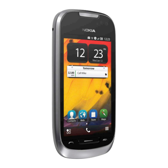
Nokia 701
RM-774
Transceiver characteristics
Band
GSM 850/900/1800/1900 MHz
WCDMA 850/900/1700/1900/2100 MHz
Display
3.5-inch nHD resolution (640x360); TFT-LCD
Camera
8 megapixel full focus (EDOF) CMOS, dual LED-flash,
1280x720 30fps HD video recording
Operating System
Symbian Belle
Connections:
WLAN IEEE802.11 b/g/n with UPnP support
Micro USB 2.0
Bluetooth 3.0 + EDR
NFC (Near Field Connection)
Stereo audio out via 3.5mm AV connector
Talk time
GSM: Up to 15 hours
WCDMA: Up to 6.75 hours
Note:
Talk times are dependent on network parameters
and phone settings
Conf idential | Copyright © 2011 Nokia | A ll rights reserved
Nokia 701 (RM-774)
L1L2 Service Manual
Standby
GSM: Up to 504 hours
WCDMA: Up to 551 hours
Version 4.0
Advertisement
Table of Contents


Need help?
Do you have a question about the 710 and is the answer not in the manual?
Questions and answers