Table of Contents
Advertisement
Quick Links
User Manual
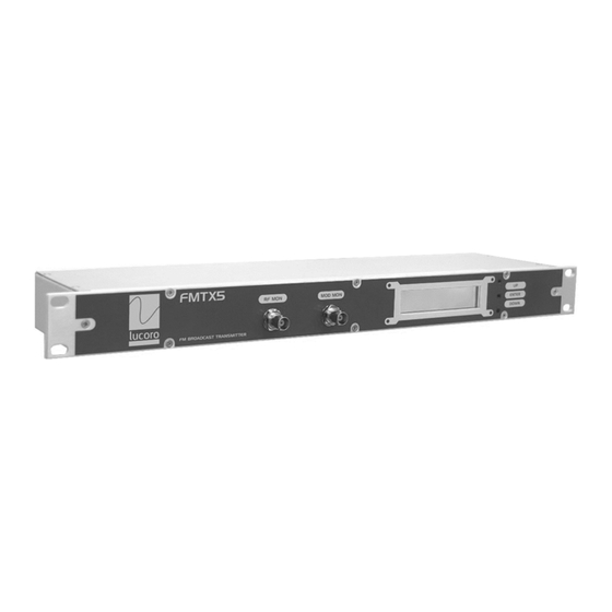
FMTX5
Stereo FM Transmitter with integrated
Audio Processor, Stereo Encoder
and RDS Encoder
WARNING!
This Transmitter is capable of generating RF potential. Touching
internal parts, or the connected antenna system, may cause RF
burns. Antenna systems should be installed such that exposure
by any person to RF fields cannot exceed safe limits. The
permitted limits vary from country to country. Expert advice
should be sought about the safe installation of this transmission
system.
RISK OF FIRE!
RF (Radio Frequency) energy could cause ignition of combustible
surfaces during fault conditions. Installation should be left to
qualified personnel. RF can cause burns to skin. Ensure antenna
systems and feeder cables are not situated near, or could fall
onto, any combustible surface.
Advertisement
Table of Contents

Related Manuals for lucoro FMTX5

Summary of Contents for lucoro FMTX5
- Page 1 User Manual FMTX5 Stereo FM Transmitter with integrated Audio Processor, Stereo Encoder and RDS Encoder WARNING! This Transmitter is capable of generating RF potential. Touching internal parts, or the connected antenna system, may cause RF burns. Antenna systems should be installed such that exposure by any person to RF fields cannot exceed safe limits.
- Page 2 WARNING! Never operate this device without a suitable 50 ohm load connected to the RF OUTPUT socket, or without a suitably installed and matched antenna system connected. Although the output of this transmitter is protected against antenna load faults, MIS-OPERATION MAY RESULT IN DAMAGE NOT COVERED BY ANY WARRANTY.
-
Page 3: Before Operating
RadioTEXT messages (eg. “Now playing…”). At the heart of the FMTX5 is a high quality PLL modulator, and the RF Power Amplifier uses the latest high-gain Enhancement Mode MOSFET device, achieving new levels of efficiency and reliability. - Page 4 Use of this device as part of a transmission system, or combined transmission system not specified by the manufacturer, may require further testing to ensure that it remains compliant with the essential requirements and other relevant provisions of current EU Low Voltage, EMC and Radio Equipment Directives.
- Page 5 The transmitter should be serviced by qualified service personnel if it does not appear to operate normally, exhibits a marked change in performance, has been subjected to shock, damage, moisture, or if foreign objects have ingressed. The user should not attempt to service the transmitter beyond that which is described in the Operating Instructions.
-
Page 6: Controls And Connectors
Controls and Connectors 1. RF MON BNC connector for monitoring of the RF output. Output level will be the RF output level attenuated by approximately 40dB. Not to be used for measurement of harmonics. 2. MPX MON BNC connector for monitoring of the input to the modulator (baseband spectrum). - Page 7 10. USB Port. Connect a Windows™ PC or Laptop to program the RDS content. Free software can be downloaded at: https://lucorobroadcast.com/support 11. RF OUT 'N' Socket. Connect a matched, pre-tested antenna system with a return loss of >=14dB to this socket. Ensure all parts of the feeder and antenna system are rated for 10W or above 12.
-
Page 8: Display & Menu
“ALARM!” will show in place of the forward power reading, and the RF output will cease. Try resetting the FMTX5, by switching the power off, waiting 15 seconds and then switching the power back on. Should the reflected RF power be too high, “ALARM!” will show in place of the reflected power reading, and the RF output will cease. - Page 9 2. Press ‘ENTER’ to select the RF Power value. Use the ‘UP’ and ‘DOWN’ buttons to select the desired RF power output level. 3. Press ‘ENTER’ button to save the new setting. Setting the Transmission Frequency 1. Press the ‘ENTER’ button. The Settings Menu will appear. 2.
-
Page 10: Installation
Installation Connect a suitable rated test load to the RF OUPUT socket before connecting the unit to mains power. IMPORTANT! FAILURE TO DO SO MAY RESULT IN DAMAGE NOT COVERED BY WARRANTY. Begin by setting the correct operational mode. The unit is supplied from the factory ready for audio operation. If the audio inputs are to be used, skip this step. - Page 11 Using the front panel display and buttons, set the desired transmission frequency. See ‘Setting the Transmission Frequency’. After changing the carrier frequency, the modulation (deviation) level may have increased or decreased slightly. Using a calibrated test set, check the deviation, and adjust if necessary. ELECTRIC SHOCK AND RF BURN HAZARD! DISCONNECT THE POWER BEFORE REMOVING ANY COVERS.
-
Page 12: Operation
Operation The transmitter is designed for continuous reliable transmission, however it is advisable to check the installation periodically checked for correct operation and free airflow. The following are LCD display fault indicators and their meaning: Should ALARM! appear in place of the forward power reading, the system has detected there is no forward power. -
Page 13: Network Connection
Network Connection The FMTX5 will be supplied with a notification of its factory-set IP address, username and password. KEEP THESE DETAILS SAFE. Whilst the transmitter’s network configuration can be changed, the username and password are fixed. Enter the factory-set IP address in the address bar of an internet browser. - Page 14 Schedule regular checks, on an on-going basis, to ensure that the Router is running the very latest manufacturer’s firmware. Lucoro Broadcast take no liability whatsoever for damage or losses caused by a successful network attack.
-
Page 15: Audio Processor
Audio Processor The high-quality integrated audio processor is more than an audio limiter found on most transmitters. It has all of the features of expensive broadcast processors, including: Slow gain-riding section (AGC). This will optimise all sources for equal volume over time. So if one studio operator drives the mixing desk louder or quieter than others, the level will compensate accordingly. - Page 16 When setting-up the transmitter for the first time, the ‘fixed’ RDS content must be programmed via the USB interface, using a Windows™ PC or Laptop running the free software available at lucorobroadcast.com/support. 1. Connect a USB cable to the USB port on the rear of the transmitter. If the transmitter is not in service apply power.
-
Page 17: Radio Text
PS (Station Name): Maximum 8 characters including punctuation and spaces. Enter the station name, as you would like it to appear on RDS displays (eg. “Hits FM”). PI (Hex Code): Issued by the broadcast regulator, this is a 4 digit Hexadecimal code unique to your station (eg. - Page 18 The FMTX-series uses a transparent ASCII protocol, to suit a number of radio playout systems with the minimum of additional data processing or interfacing requirements. IMPORTANT! The 9-way D-Sub connector on the rear of the transmitter is used for a number of control and monitoring functions. The RS232 input for the RDS dynamic RadioTEXT feature shares this connector, therefore pin connections are not the same as a standard RS232 port.
- Page 19 Remember to send the RDS TA Off character immediately after each travel bulletin. Misuse of the RDS Traffic Announcement feature will result in sanctions by the broadcasting authority. RDS TA can also be activated and deactivated via the transmitter’s 9-way ‘D’-sub connector. Broadcasters planning to use the RDS TA feature, either via RS232 or via the 9-way ‘D’-sub connector, MUST ensure that the ‘TP’...
- Page 20 Declaration of Conformity Lucoro Broadcast Clay Pit Lane Roecliffe York YO51 9FS hereby take sole responsibility to confirm that the products: FMTX5 which this declaration refers to, conforms to all applicable requirements of EU Directive 2014/53/EU and is CE marked...
-
Page 21: Technical Specifications
Technical Specifications Frequency range 87.5 to 108.00MHz Frequency stability Better than ±200Hz Output power 0.5 – 6W (nominal) Harmonic & spurious output -75dBc typical AM Noise <0.5% @ ±40kHz deviation <0.15%@ ±75KHz deviation RF output connector ‘N’ type (F) Monitoring: BNC (F) -40dB 50 ohms BNC (F) 1V P-P 10K ohms Audio Interface:... - Page 22 WEEE - Waste Electrical and Electronic Equipment The equipment that you bought has required the extraction and use of natural resources for its production. It may contain hazardous substances that could impact health and the environment. In order to avoid the dissemination of those substances in our environment and to diminish the pressure on the natural resources, we encourage you to use the appropriate take-back systems.
- Page 23 No part of this document may be reproduced or transmitted, in any form, by any means, without prior written consent of the Lucoro Broadcast. Lucoro Broadcast shall not be liable for any direct, indirect, incidental, consequential or other damage or loss alleged in connection with the supply or use of this product.
Need help?
Do you have a question about the FMTX5 and is the answer not in the manual?
Questions and answers