Table of Contents
Advertisement
Advertisement
Table of Contents

Subscribe to Our Youtube Channel
Related Manuals for Toro TITAN MX5480


Summary of Contents for Toro TITAN MX5480
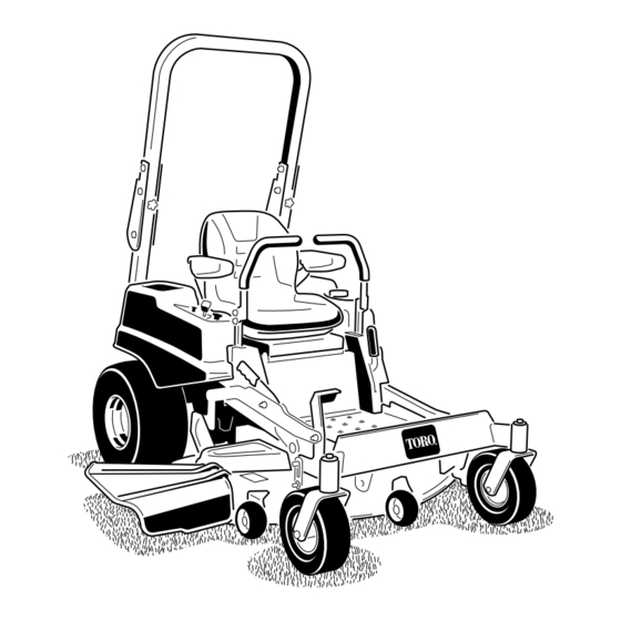
- Page 1 Form No. 3375-775 Rev A TITAN MX4880, MX5480, and MX6080 Zero-Turn-Radius Riding Mower Model No. 74871—Serial No. 313000001 and Up Model No. 74872—Serial No. 313000001 and Up Model No. 74873—Serial No. 313000001 and Up g020432 *3375-775* A Register at www.Toro.com. Original Instructions (EN)
-
Page 2: Introduction
You are responsible for operating the product properly and safely. WARNING You may contact Toro directly at www.Toro.com for product and accessory information, help finding a dealer, or to register CALIFORNIA your product. -
Page 3: Table Of Contents
Introduction ..............2 if you do not follow the recommended precautions. Safety ................4 Safe Operating Practices........... 4 Toro Riding Mower Safety ........6 Slope Indicator ............7 Safety and Instructional Decals ......... 8 Figure 2 Setup ................14 1. -
Page 4: Safety
In these instances, Toro has refined the statement to convey the meaning of the standard while better matching the product this Operator's Manual pertains. Safety information in addition to the instructions found in the ANSI standard below can be found in Toro Riding Mower Safety at the end of this section. - Page 5 Weight transfer to the front wheels may cause drive A hitch kit is available for this machine and can be obtained wheels to slip and cause loss of braking and steering. by contacting an Authorized Toro Dealer. Do not tow...
-
Page 6: Toro Riding Mower Safety
• Extinguish all cigarettes, cigars, pipes and other sources • Use only genuine Toro replacement parts to ensure that of ignition. original standards are maintained. • Use only an approved fuel container. Toro Riding Mower Safety •... -
Page 7: Slope Indicator
Slope Indicator G011841 Figure 3 This page may be copied for personal use. 1. The maximum slope you can safely operate the machine on is 15 degrees. Use the slope chart to determine the degree of slope of hills before operating. Do not operate this machine on a slope greater than 15 degrees. Fold along the appropriate line to match the recommended slope. -
Page 8: Safety And Instructional Decals
Safety and Instructional Decals Safety decals and instructions are easily visible to the operator and are located near any area of potential danger. Replace any decal that is damaged or lost. 93-7009 1. Warning—don't operate the mower with the deflector up or removed;... - Page 9 110-6691 1. Thrown object hazard—keep bystanders a safe distance from the machine. 2. Thrown object hazard, mower—do not operate without the deflector, discharge cover, or grass collection system in place. 3. Cutting/dismemberment of hand or foot—stay away from moving parts. 112-9840 115-9644 1.
- Page 10 Battery Symbols Some or all of these symbols are on your battery 1. Explosion hazard 6. Keep bystanders a safe distance from the battery. 117–1158 2. No fire, open flame, or 7. Wear eye protection; smoking. explosive gases can 1. Bypass lever position for 2.
- Page 11 115-9630 1. Read the Operator's Manual before performing any 4. Check the hydraulic oil every 25 hours maintenance. 2. Check the engine oil every 8 hours 5. Check the caster wheel tire pressure every 25 hours 3. Check the drive wheel tire pressure every 25 hours 6.
- Page 12 120-5466 1. Warning—read the Operator's Manual. 5. Loss of traction/control hazard, slopes—loss of traction/control on a slope, disengage the blade control switch (PTO), proceed off the slope slowly. 2. Warning—read the instructions before servicing or performing 6. Crushing/dismemberment hazard of bystanders, maintenance;...
- Page 13 120-7113 1. Fuel 2. Full 3. Half 4. Empty...
-
Page 14: Setup
Setup Loose Parts Use the chart below to verify that all parts have been shipped. Procedure Description Qty. – No parts required Connect the battery. – No parts required Check the mower adjustment. Ignition Key Hose coupling Operator's Manual Complete the Setup. Engine Operator's Manual Operator Training Material Connecting the Battery... -
Page 15: Completing The Setup
Completing the Setup Parts needed for this procedure: Ignition Key Hose coupling Operator's Manual Engine Operator's Manual Operator Training Material Procedure Setting Up the Motion Control Levers If needed, remove the upper bolt, washer and nut and raise the motion control levers to the upright position. Secure the motion control levers. -
Page 16: Product Overview
Product Overview G015763 Figure 5 1. Drive wheel 4. Motion control levers 7. Front caster wheel 10. Deflector 2. Operator seat 5. Parking brake 8. Anti-scalp roller 3. Roll over protection system 6. Footrest 9. Foot pedal deck lift and (ROPS) height-of-cut G014766... -
Page 17: Controls
It operates when the blade control switch (PTO) is its capabilities. Contact your Authorized Service Dealer or engaged. Use these times for scheduling regular maintenance Distributor or go to www.Toro.com for a list of all approved (Figure 7). attachments and accessories. -
Page 18: Operation
Using the Rollover Protection Operation System (ROPS) Note: Determine the left and right sides of the machine from the normal operating position. WARNING To avoid injury or death from rollover: keep the roll Think Safety First bar in the fully raised locked position and use the Please carefully read all of the safety instructions and decals seat belt. -
Page 19: Adding Fuel
G015035 DANGER In certain conditions, gasoline is extremely flammable and highly explosive. A fire or explosion from gasoline can burn you and others and can damage property. • Fill the fuel tank outdoors, in an open area, when the engine is cold. Wipe up any gasoline that spills. -
Page 20: Checking The Engine Oil Level
tank allows the fuel to expand. Overfilling may result in WARNING fuel leakage or damage to the engine or emission system. Gasoline is harmful or fatal if swallowed. Long-term 1. Clean around the fuel tank cap and remove the cap. exposure to vapors can cause serious injury and illness. -
Page 21: Operating The Throttle
Setting the Parking Brake G020305 Figure 14 Releasing the Parking Brake G008959 Figure 17 1. On 2. Off Operating the Ignition Switch G020306 Figure 15 1. Turn the ignition key to the Start position (Figure 18). When the engines starts, release the key. Important: Do not engage starter for more than 5 seconds at a time. -
Page 22: Starting And Stopping The Engine
Starting and Stopping the Note: If the fuel system was depleted of fuel—add fuel to the machine and use additional starting cycles Engine when starting the engine. Starting the Engine 1. Sit down on the seat (Figure 19) and fasten the seat belt. 2. -
Page 23: Operating The Mower Blade Control Switch (Pto)
Disengaging the Blade Control Switch (PTO) 00:60 Sec G009174 Figure 23 The Safety Interlock System WARNING If safety interlock switches are disconnected or damaged the machine could operate unexpectedly causing personal injury. • Do not tamper with the interlock switches. •... -
Page 24: Driving Forward Or Backward
Using the Motion Control Levers 3. While sitting on the seat, engage the parking brake, move the blade control switch to Off, and lock the motion control levers in neutral. Start the engine. While the engine is running, release the parking brake, engage the blade control switch, and rise slightly from the seat;... -
Page 25: Stopping The Machine
Stopping the Machine To stop the machine, move the traction control levers to neutral and move to locked position, disengage the blade control switch (PTO), and turn the ignition key to off. Set the parking brake when you leave the machine; refer to Operating the Parking Brake (page 20). - Page 26 G010236 Figure 28 1. Deck lift pedal 4. Lock position. lowest height-of-cut (use only for deck removal) G010219 2. Cut height pin 5. Lock position. transport Figure 27 position Transport Lock Position 3. Height-of-cut positions Using the Lock Positions Adjusting the Height-of-Cut The deck can be locked in the highest height-of-cut or The height-of-cut can be adjusted from 1-1/2 to 4-1/2 inch transport position or the lowest height-of-cut position.
-
Page 27: Adjusting The Anti-Scalp Rollers
Adjusting the Anti-Scalp Positioning the Seat Rollers The seat can move forward and backward. Position the seat where you have the best control of the machine and are most Whenever you change the height-of-cut, it is recommended comfortable. to adjust the height of the anti-scalp rollers. To adjust, move the lever sideways to unlock seat (Figure 30). -
Page 28: Pushing The Machine By Hand
Adjusting the Tilt The motion control levers can be tilted forward or backward for maximum operator comfort. 1. Loosen the upper bolt holding the control lever to the control arm shaft. 2. Loosen the lower bolt just enough to pivot the control lever forward or backward. -
Page 29: Using The Side Discharge
Using the Side Discharge The mower has a hinged grass deflector that disperses clippings to the side and down toward the turf. DANGER Without a grass deflector, discharge cover, or complete grass catcher assembly mounted in place, you and others are exposed to blade contact and thrown debris. -
Page 30: Operating Tips
Operating Tips cutting height higher than usual and cut the grass at this setting. Then cut the grass again using the lower, normal setting. Fast Throttle Setting When Stopping For best mowing and maximum air circulation, operate the engine at the fast throttle position. Air is required to If the machine's forward motion must be stopped while thoroughly cut grass clippings, so do not set the height-of-cut mowing, a clump of grass clippings may drop onto your lawn. -
Page 31: Maintenance
Maintenance Recommended Maintenance Schedule(s) Maintenance Service Maintenance Procedure Interval • Change the engine oil. After the first 8 hours • Change the hydraulic system filter and oil. After the first 50 hours • Check the safety interlock system. • Check the engine oil level. •... - Page 32 Figure 33 Located on the seat pan underside 1. Read the Operator's Manual before performing any 4. Check the hydraulic oil every 25 hours maintenance. 2. Check the engine oil every 8 hours 5. Check the caster wheel tire pressure every 25 hours 3.
-
Page 33: Premaintenance Procedures
Premaintenance Lubrication Procedures Greasing the Bearings Raising the Seat Service Interval: Every 25 hours—Grease all lubrication points. Make sure the motion control levers are the neutral lock Grease Type: No. 2 General Purpose Lithium Base Grease position and parking brake is set. Lift and hold the lever behind the seat forward to disengage the seat latch and then 1. -
Page 34: Engine Maintenance
Engine Maintenance Cleaning the Element Service Interval: Every 100 hours—Service the paper element. (more often in dusty, dirty WARNING conditions) Contact with hot surfaces may cause personal Every 200 hours/Yearly (whichever comes injury. first)—Replace the paper element. (more often in dusty, dirty conditions) Keep hands, feet, face, clothing and other body 1. - Page 35 engine with oil below the low mark because the engine 2. Disengage the PTO, move the motion control levers to may be damaged. the neutral locked position and set the parking brake. 1. Park the machine on a level surface, disengage the 3.
-
Page 36: Servicing The Spark Plug
4. Slowly pour approximately 80% of the specified oil into the filler tube and slowly add the additional oil to bring it to the Full mark (Figure 39). G008796 Figure 39 G008748 Figure 40 Changing the Engine Oil Filter Note: Ensure the oil filter gasket touches the engine and then an extra 3/4 turn is completed. -
Page 37: Cleaning The Cooling System
Removing the Spark Plug Installing the Spark Plug 1. Disengage the PTO, move the motion control levers to Tighten the spark plug(s) to 16 ft-lb (22 N-m). the neutral locked position and set the parking brake. 2. Stop the engine, remove the key, and wait for all moving parts to stop before leaving the operating position. -
Page 38: Fuel System Maintenance
Fuel System Maintenance DANGER In certain conditions, gasoline is extremely flammable and highly explosive. A fire or explosion from gasoline can burn you and others and can damage property. • Perform any fuel related maintenance when the engine is cold. Do this outdoors in an open area. Wipe up any gasoline that spills. -
Page 39: Electrical System Maintenance
Electrical System 1. Disengage the blade control switch (PTO), move the motion control levers to the neutral lock position and Maintenance set the parking brake. 2. Stop the engine, remove the key, and wait for all moving parts to stop before leaving the operating position. Servicing the Battery 3. -
Page 40: Servicing The Fuses
Charging the Battery 3. Install a new fuse having the same amperage as the fuse that you removed (Figure 48). WARNING Charging the battery produces gasses that can explode. Never smoke near the battery, and keep sparks and flames away from battery. Important: Always keep the battery fully charged. -
Page 41: Drive System Maintenance
Drive System Hydraulic System Maintenance Maintenance Oil Type: 20w-50 engine oil. Checking the Tire Pressure System Capacity: approximately 4.495 liter (152 oz) with a filter change. Service Interval: Every 25 hours—Check tire pressure. Important: Use oil specified or equivalent. Other fluids Maintain the air pressure in the front and rear tires as could cause system damage. - Page 42 Removing Hydraulic System Filters 1. Stop engine, wait for all moving parts to stop, and allow engine to cool. 2. Remove the key and engage the parking brake. 3. Locate the filter and guards on each transaxle drive system (Figure 51). 4.
-
Page 43: Mower Deck Maintenance
File down any nicks and sharpen the blades as necessary. If a blade is damaged or worn, replace it immediately with a genuine Toro replacement blade. For convenient sharpening and replacement, you may want to keep extra blades on hand. - Page 44 3. Measure from the tip of the blade to the flat surface here. Figure 54 1. Cutting Edge 3. Wear/slot Forming G014973 2. Curved Area 4. Crack Figure 56 Checking for Bent Blades 1. Blade, in position for measuring Note: The machine must be on a level surface for the 2.
- Page 45 1/8 inch (3mm), the blade spindle could be bent. from both cutting edges. Contact an Authorized Toro Dealer for service. B. If the variance is within constraints, move to the next blade..
-
Page 46: Mower Deck Leveling
Figure 61 1. Blade 2. Balancer Installing the Blades 1. Install the blade onto the spindle shaft (Figure 59). Figure 62 Important: The curved part of the blade must be pointing upward toward the inside of the mower to 1. Blades side to side 3. -
Page 47: Inspecting The Belts
Note: Make sure that the deck hangers are all the way down (at the top of the slot) and the deck lift foot lever is pushed back against the stop (Figure 65). 6. Tighten the four leveling adjust locking nuts (Figure 65). Figure 63 1. - Page 48 1. Install the new belt around the mower pulleys and the G015789 clutch pulley under the engine (Figure 67). Figure 66 2. Using a spring removal tool (Toro part no. 92-5771), 1. Loosen the screws 3. Remove belt cover install the idler spring over the deck post and place 2.
-
Page 49: Removing The Mower
G010309 Figure 69 1. Hair pin cotter 3. Washer 2. Link bar G015790 Figure 68 2. Remove the hardware from the front and rear deck hangers on both sides of the deck (Figure 70). 1. Position the belt cover and 3. -
Page 50: Installing The Mower
Installing the Mower 1. Park the machine on a level surface and disengage the blade control switch. 2. Move the motion control levers outward to the neutral lock position, stop the engine, remove the key, set the parking brake and wait for all moving parts to stop before leaving the operating position. -
Page 51: Cleaning
Cleaning Washing the Underside of the Mower Service Interval: After each use—Clean the mower housing. Wash the underside of the mower after each use to prevent grass buildup for improved mulch action and clipping dispersal. 1. Park the machine on a level surface and disengage the blade control switch. -
Page 52: Waste Disposal
Storage Note: If the mower is not clean after one washing, soak it and let it stand for 30 minutes. Then repeat the process. Cleaning and Storage 8. Run the mower again for 1 to 3 minutes to remove 1. Disengage the blade control switch (PTO), set the excess water. - Page 53 D. Restart the engine and run it until it stops. E. Dispose of fuel properly. Recycle as per local codes. Important: Do not store stabilizer/conditioned fuel over 90 days. 13. Check and tighten all bolts, nuts, and screws. Repair or replace any part that is damaged.
-
Page 54: Troubleshooting
Troubleshooting Problem Possible Cause Corrective Action The starter does not crank. 1. Blade control switch (PTO) is engaged. 1. Move blade control switch (PTO) to disengaged. 2. Parking brake is not on. 2. Set the parking brake. 3. Drive levers are not in neutral lock 3. - Page 55 Problem Possible Cause Corrective Action The machine does not drive. 1. By pass valves is not closed tight. 1. Tighten the by pass valves. 2. Pump belt is worn, loose or broken. 2. Change the belt. 3. Pump belt is off a pulley. 3.
-
Page 56: Schematics
Schematics G014723 Wire Diagram (Rev. B) - Page 57 Notes:...
- Page 58 Notes:...
- Page 59 Notes:...
- Page 60 Toro importer. If all other remedies fail, you may contact us at Toro Warranty Company. Australian Consumer Law: Australian customers will find details relating to the Australian Consumer Law either inside the box or at your local Toro Dealer.
Need help?
Do you have a question about the TITAN MX5480 and is the answer not in the manual?
Questions and answers