Table of Contents
Advertisement
Additional copies of this manual may be purchased from
YOUR AUTHORIZED CLARK DEALER
CLARK MATERIAL HANDLING COMPANY
700 Enterprise Drive
Lexington, Kentucky 40510 [ www.clarkmhc.com ]
●
Printed Date : Mar. 2023
ELECTRIC RIDER LIFT TRUCKS
[Do not remove this manual from the truck]
ECX 20/25/30/32
TMX 12/15s/15/17/20/25
GEX 16/18/20s/20/25/30s/30/32
GTX 16/18/20s
Part No. OM-1039 (Eng)
Book No. OM 1039 (Rev 1.4)
Mar. 2023
Advertisement
Chapters
Table of Contents

Related Manuals for Clark ECX 25


Summary of Contents for Clark ECX 25
- Page 1 ELECTRIC RIDER LIFT TRUCKS Additional copies of this manual may be purchased from YOUR AUTHORIZED CLARK DEALER [Do not remove this manual from the truck] ECX 20/25/30/32 TMX 12/15s/15/17/20/25 GEX 16/18/20s/20/25/30s/30/32 GTX 16/18/20s Part No. OM-1039 (Eng) CLARK MATERIAL HANDLING COMPANY Book No.
- Page 2 Operator’s Manual You must be trained and authorized to operate a lift truck. YOU can prevent accidents First: Learn safe operating rules and your company rules. Next: Read your Operator’s Manual. If you do not understand it, ask your supervisor for help. Learn about the unit you operate.
-
Page 3: A Message To Clark Lift Truck Operators
They require specific instructions and rules for safe operation and maintenance. Safe operation of lift trucks is of primary importance to CLARK. Our experience with lift truck accidents has shown that when accidents happen and people are killed or injured, the causes are: •... - Page 4 If you think you need training in operating or inspecting your lift truck, ask your supervisor. CLARK lift trucks are built to take hard work, but not abuse. They are built to be dependable, but they are only as safe and efficient as the operator and the persons responsible for maintaining them.
-
Page 6: Table Of Contents
Contents of this Manual A Message to CLARK Lift Truck Operators....... ii Introduction ................ vi How to Use this Manual ..........viii Safety Signs and Safety Messages ........x Section 1. General Safety Rules ........1-1 Section 2. Operating Hazards .......... 2-1 Section 3. -
Page 7: Introduction
CLARK lift truck in a safe and correct manner. Your CLARK lift truck has been designed and built to be as safe and efficient as today’s technology can make it. As manufactured, it meets all the applicable mandatory requirements of ANSI / ITSDF B56.1 Safety Standard for Powered Industrial Trucks. - Page 8 The procedures for a periodic planned maintenance program that covers inspections, operational checks, cleaning, lubrication, and minor adjustments are outlined in this manual. Your CLARK dealer is prepared to help you with a Planned Maintenance Program by trained service personnel who know your lift truck and can keep it operating safely and efficiently.
-
Page 9: How To Use This Manual
Also, the Index helps you locate information about various topics. NOTICE: The descriptions and specifications included in this manual were in effect at the time of printing. CLARK Material Handling Company reserves the right to make improvements and changes in specifications or design. - Page 10 If the truck you operate is not equipped with a manual, ask your supervisor to obtain one and have it attached to the truck. And, remember, your CLARK dealer is pleased to answer any questions about the operation and maintenance of your lift truck and will provide you with additional information should you require it.
-
Page 11: Safety Signs And Safety Messages
Damage to the truck, death, or serious injury to you or other persons may result if these messages are not followed. If warning decals are damaged, they must be replaced. Contact your CLARK dealer for replacements. NOTICE This message is used when special information, instruc-... - Page 12 Section 1. General Safety Rules General Safety Rules Contents Daily Inspection ............. 1-2 Do’s and Don’ts ............1-3 Seat Belts ..............1-4 No Riders ..............1-5 Pedestrians ............. 1-6 Operator Protection ..........1-7 Fork Safety ............. 1-8 Pinch Points ............1-9 Travel ..............
-
Page 13: Daily Inspection
Daily Inspection At the beginning of each shift, inspect your truck and fill out a daily inspection sheet. Check for damage and maintenance problems. Have repairs made before you operate the truck. CAUTION DO NOT MAKE REPAIRS YOURSELF. Lift truck mechanics are trained professionals. -
Page 14: Do's And Don'ts
Section 1. General Safety Rules Do’s and Don’ts Don't mix drugs or alcohol with your job. Do watch for pedestrians. Don't block safety or emergency equipment. Do wear safety equipment when required. Don't smoke in "NO SMOKING" areas or when refueling. Do’s and Don’ts... -
Page 15: Seat Belts
Seat Belts ALWAYS BUCKLE UP Seat belts can reduce injuries. Seat Belts... -
Page 16: No Riders
Section 1. General Safety Rules No Riders No Riders... -
Page 17: Pedestrians
Pedestrians Estar atento cuando se maneja. Mirar en el sentido de marcha. Los peatones pueden estar usando la misma vía Watch where you are going. Look in the direction of que usted. Sonar la bocina en todas las intersecciones o travel. -
Page 18: Operator Protection
Section 1. General Safety Rules Operator Protection Keep under the overhead guard. Always keep your body within the confines of the truck. Operator Protection... -
Page 19: Fork Safety
Fork Safety Never allow anyone to walk under raised forks. DANGER There is special equipment to raise 2372604 people for overhead work. DO NOT USE LIFT TRUCKS. Fork Safety... -
Page 20: Pinch Points
Section 1. General Safety Rules Pinch Points WARNING Keep hands, feet and legs out of the upright. WARNING Don't use the upright as a ladder. CAUTION Never try to repair the upright, carriage, chain, or attachment yourself! Always trained mechanic. Pinch Points... -
Page 21: Travel
Travel Travel with the load near floor/ground with upright tilted back to cradle the load whenever possible. Never lift or lower the load when the truck is in motion. When handling bulky loads that restrict your vision, operate your truck reverse improve visibility. -
Page 22: Grades, Ramps, Slopes, And Inclines
Section 1. General Safety Rules Grades, Ramps, Slopes, and lnclines Unloaded Forks Downgrade WARNING Never turn on a grade, either loaded or unloaded. Loaded Forks Upgrade Grades, Ramps, Slopes, and lnclines 1-11... -
Page 23: Surface And Capacity
Surface and Capacity Avoid these conditions. They can cause a truck to tip over or lose traction for braking or driving. WARNING Know the weight of your truck and load. Especially when using elevators. Know the capacity of the elevator you intend to use. -
Page 24: Tip-Over
Section 1. General Safety Rules Tip-Over Lateral Tip-over Lateral tip-over can occur with a com- • bination of speed and sharpness of turn. This combination will exceed the stability of the truck. This condition is even more likely with an unloaded truck. -
Page 25: What To Do In Case Of A Tip-Over
What to do in Case of a Tip-over If your truck starts to tip over, WARNING DO NOT JUMP!!! IMPORTANT Your chances for survival in a tip-over are better if you stay with the truck, in your seat. Brace yourself as illustrated below! 1. -
Page 26: Parking
Section 1. General Safety Rules Parking • Never park on a grade. • Always come to a complete stop before leaving truck. • Be sure travel control is in NEUTRAL. • Lower forks fully to floor and tilt forward. • Set parking brake. •... -
Page 27: General Tire Maintenance, Inspection, And Repair
General Tire Maintenance, Inspection, and Repair 1. Park the truck as described on page 1-15 and check for correct tire inflation air pressure. See specifications in this OM for cor- rect tire pressure for your truck. CAUTION Check tire pressure from a position facing the tread of the tire, not the side. - Page 28 Section 2. Operating Hazards Operating Hazards Contents Loose Loads ............2-2 Long or Wide Loads / Rear Swing ......2-3 Low Overhead Clearance Fast Turns and High Loads ........2-4 Docks/Drop Offs ............. 2-5 Right-Angle Stacking ..........2-6 Chain Slack ............. 2-7 Pallets and Skids ...........
-
Page 29: Loose Loads
Loose Loads WARNING Loose or unbalanced loads dangerous. Observe these precautions. Never carry loose or uneven material. Center wide loads. Stack and band loose material. Loose Loads... -
Page 30: Long Or Wide Loads / Rear Swing
Section 2. Operating Hazards Long or Wide Loads / Rear Swing WARNING With long or wide loads, you need more room. So slow down and watch your clearance. A long load reduces the capacity of the truck. Know and understand your truck load rating. When extra-long material makes it necessary to travel with the load elevated, do so with extreme care and be alert to load end- swing when turning. -
Page 31: Low Overhead Clearance Fast Turns And High Loads
Low Overhead Clearance Fast Turns and High Loads WARNING Know the height of your truck, with and without a load. Check your clearances. Keep the load low and tilted back. WARNING Watch overhead clearance: Moving into overhead structures can tip a truck over, or spill a load. -
Page 32: Docks/Drop Offs
Section 2. Operating Hazards Docks/Drop Offs WARNING To avoid these hazards, you must: • Talk to the truck driver yourself; make sure the driver does not move the trailer until you are done! • Apply trailer brakes. • Use wheel chocks. •... -
Page 33: Right-Angle Stacking
Right-Angle Stacking SLOWLY WARNING When right-angle stacking or moving with a raised load to clear low objects, avoid sharp turns and move slowly. Right-Angle Stacking... -
Page 34: Chain Slack
Section 2. Operating Hazards Chain Slack WARNING Slack chains mean rail or carriage hang-up. Raise the forks before you move, or broken chains can result. WARNING Keep hands, feet and legs out of the upright. WARNING Don't use the upright as a ladder. CAUTION Never try to repair the upright, car- riage,... -
Page 35: Pallets And Skids
Pallets and Skids WARNING Do not move or store materials on damaged pallets or skids. Items can fall through them causing severe injury or death! Be sure the pallet or skid you are using is in good condition and does not have defective or missing components and fasteners. - Page 36 Section 3. Common Truck Common Truck Contents Truck Description ..........3-2 Operator Controls ..........3-3 Contents...
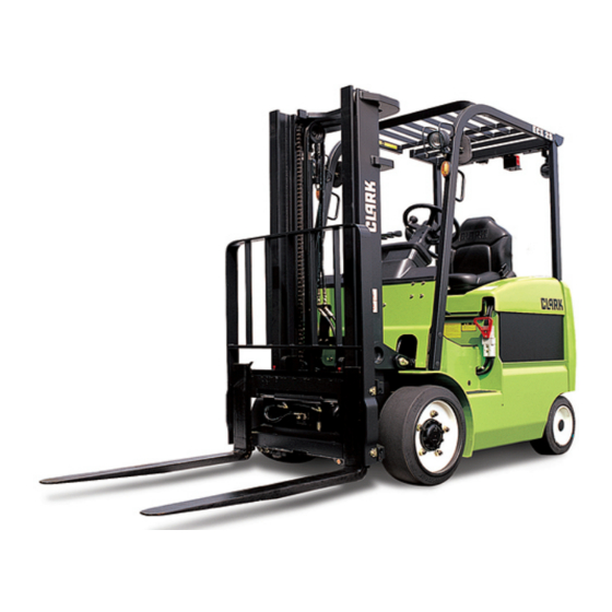
- Page 37 5. Steer Axle, Wheels/Tires 6. Upright and Carriage 7. Load Backrest 8. Forks 9. Drive Axle, Wheels/Tires The truck shown above is a typical representation of a CLARK electric sit down rider lift truck. Your model may vary Truck Description...
- Page 38 Section 3. Common Truck Operator Controls Key/Start Switch • Connects the battery with all truck operating systems (drive, lift, and steer electrical circuits) except the horn. • Connects battery to the diagnostic display hour meter and bat- tery charge status. The key switch must always be turned to the ON position to operate the truck.
- Page 39 Parking Brake The parking brake pedal or lever (depending on your model) mechanically operates the parking brake. Parking Brake Pedal To apply the parking brake, push the Parking Brake Release pedal down with your left foot until pedal stops. The parking brake release is located just above the brake pedal as shown.
- Page 40 Section 3. Common Truck Steering System steering handwheel operates steering control valve that directs the oil flow to the steering cylinder connected to the steer axle. The steering control valve can also act as a pump to provide manual steering if the hydraulic pump stops. Horn Button The horn button is located in the center hub of the steering handwheel.
- Page 41 IMPORTANT The hydraulic levers shown are Tilt typical representations CLARK lift truck. Your model may vary slightly. Lift Control Function With the lift control lever, you are able to raise and lower the fork carriage on the upright. The lifting and lowering...
- Page 42 CAUTION When attachments are added or if the truck is modified, the capacity of the truck may be affected. Contact your authorized CLARK dealer for a new nameplate showing the revised capacity. IMPORTANT OSHA requires prior written approval from the manufac- turer before any modifications affecting capacity or safety may be made.
- Page 43 Operator Safety Warning Decal WARNING Read the manual Buckle up! Apply brake when leaving truck Watch Out For Other People Most lift truck 8009529 INJURIES are to other people near the lift truck. IMPORTANT Safety and warning decals are placed in conspicuous Prevent Overturns! locations on the truck to remind you of essential pro-...
- Page 44 Section 3. Common Truck Upright Warning Decal This safety decal is on the upright to warn of the danger of injury from movement between rails, chains, sheaves, fork carriage, and other parts of the upright assembly. Do not climb on or reach into the upright.
- Page 45 3-10...
- Page 46 Section 4. Operator Compartment and Controls Operator Compartment and Controls Contents ECX Operator Compartment .......... 4-2 TMX Operator Compartment ........4-3 GEX/GTX Operator Compartment ......4-4 Contents...
- Page 47 ECX Operator Compartment 1. Steering Handwheel 2. Horn Button 3. Directional Control Lever 4. Pylon Release Lever 5. Brake Pedal 6. Seat 7. Key Switch 8. Parking Brake Pedal 9. Lift Control Lever 10. Tilt Control Lever 11. Accelerator 12. Standard Display/Command System 13.
- Page 48 Section 4. Operator Compartment and Controls TMX Operator Compartment 3, 8 1. Steering Handwheel 2. Horn Button 3. Directional Control Lever 4. Pylon Release Lever 5. Brake Pedal 6. Seat 7. Key Switch 8. Parking Brake Lever 9. Lift Control Lever 10.
- Page 49 GEX/GTX Operator Compartment 1. Steering Handwheel 2. Horn Button 3. Directional Control Lever 4. Pylon Release Lever 5. Brake Pedal 6. Seat 7. Key Switch 8. Parking Brake Lever 9. Lift Control Lever 10. Tilt Control Lever 11. Accelerator 12. Standard Display/Command System 13.
- Page 50 Section 4. Operator Compartment and Controls TMX Dash Display The primary design of the Dash Display is to provide the operator with an easily understandable, visual feedback of the status of the truck and it's system components. Standard Display 1. Pump controller & 5.
- Page 51 ECX Dash Display The primary design of the Dash Display is to provide the operator with an easily understandable, visual feedback of the status of the truck and it's system components. Standard Display 1. Park Brake 6. Battery Discharging 2. Seat Belt Alert Indicator 3.
- Page 52 Section 4. Operator Compartment and Controls GEX,GTX Dash Display The primary design of the Dash Display is to provide the operator with an easily understandable, visual feedback of the status of the truck and it's system components. 05/8/10 [WED] 1. Battery indicator 9.
- Page 53 Seat Belt: At start up this symbol displays along with an audio alarm for 4 seconds. This display reminds you to fasten your seat belt. Parking Brake: The symbol is displayed and "-01" status code appears on the numeric display when parking brake is applied.
- Page 54 Section 4. Operator Compartment and Controls Pump controller & Motor overheat warning indicator lamp & ICON (For AC Only): This indicator lamp is to warn of conditions where the temperature of pump motor and controller exceeds the limited value. If this lamp turns on, pump motor output is reduce in half....
- Page 55 Speed limit rate indicator (ECX) This indicating lamp shows the traveling speed limit rate. One segment will turn off when the speed limit rate is reduced by 10%. Displays the maximum allowable travel speed. When all segments are lit, no restriction is present.
- Page 56 Section 4. Operator Compartment and Controls Down arrow button (Mode button): Pressing this button in normal operating condition, it will move to Menu mode. Up arrow button (Enter button): Pressing this button, it will move to upper menu. Left arrow button (Slow speed button): In normal operating condition, it will select/release Slow speed.
- Page 57 4-12...
- Page 58 Section 5. Operating Procedures Operating Procedures Contents Before Operating the Truck ......... 5-2 Starting from a Safe Condition ......5-3 Contents...
- Page 59 Before Operating the Truck sure that have read understand information this Operator's Manual before operating the lift truck. The Operator's Manual Holder is located on the back of the seat. WARNING • This equipment can be dangerous if not used properly. Safe operation is the responsibility of the operator.
- Page 60 Section 5. Operating Procedures Starting from a Safe Condition Always start from a safe condition. Before operating a lift truck, make sure that: 1. Parking brake is applied. 2. Forks are fully lowered to the floor or ground. 3. You are familiar with how all the controls function and have read the Operator Manual.
- Page 61 Adjusting the Seat Adjust the seat to a comfortable position for you. Adjust the seat by rotating the release lever Back Reclining upward at the front under of the Adjustment seat. Put the seat in a position that will provide easy reach to all controls.
- Page 62 Section 5. Operating Procedures Adjusting the armrest of the driver's seat • Loosen the armrest adjustment clamping screw (1). • Move the armrest (2) to the desired position. • Tighten the clamping screw (1) again. WARNING The clamping screw must be tight.
- Page 63 Tilting the mast forward • Push the control lever (1) forward. Tilting the mast back • Pull the control lever (1) back. Raising the fork carriage WARNING Do not step on the raised forks. Increased danger of falling and being squeezed. •...
- Page 64 Section 5. Operating Procedures Using the Display LCD Back Light ( • LCD back light is linked to the Key switch. When the start key turns on. The LCD back light will illuminate. DISPLAY Initial Start-up ( • KEY ON - All the Icons and Buzzers will be ON for 1 second to check the indicating conditions....
- Page 65 • Speed (MPH) is shown when the truck is moving. Message display (GEX/GTX) The model name, POWER selection, travel direction, Normal warning and error message are displayed. Error In normal operating condition: Model name/POWER/Travel Warning BATTERY LOW direction. When several messages are simultaneously displayed, it will be displayed in the order of Error, Warning and Normal condition.
- Page 66 Section 5. Operating Procedures Diagnostic Display Code Condition Likely Corrective Action -001 Seat switch open Sit on seat -061, -065 ,-140, Overheat of motor and Restart after cooling down -203, -207 controller Replace with charged bat- -066, -208 Low battery voltage tery Before starting, place the Forward/Reverse lever to...
- Page 67 Positioning Forks and Upright When driving, with or without a load, it is good practice to have the forks slightly raised and tilt the upright (forks) backward. Having the forks raised and tilting back prevents the fork tips from catching on possible obstructions and reduces the wear on the fork blades from striking or dragging on the floor or ground.
- Page 68 Section 5. Operating Procedures Controlling Speed With the direction control in FORWARD or REVERSE, the parking brake released, put your foot on the accelerator pedal and push down smoothly until the truck is moving at the desired speed. Braking To stop the truck, lift your foot from the accelerator pedal and put it on the brake pedal.
- Page 69 Operating Safely IMPORTANT Safe operation is the responsibility of the operator. Watch where you are going. Don't go if you can't see. Before driving, check all around to be sure that your intended path of travel is clear of obstructions and pedestrians. While driving, alert...
- Page 70 Section 5. Operating Procedures Keep all other persons clear of the load and upright mechanism while attempting to handle a load. No riders... Do not carry passengers. The operator is the only one who should be on the truck. Always be in full control of your lift truck... Never operate a lift truck or its attachments if you are not in the designated operator's position.
- Page 71 Grades, ramps, and inclines... Use special care when operating on ramps, inclines, and uneven areas. Travel slowly. Travel straight up and down. Do not turn or drive at an angle across an incline or ramp. When the truck is loaded, travel with the load upgrade. When the truck is empty, travel with lifting mechanism (upright) downgrade.
- Page 72 Section 5. Operating Procedures CAUTION Operate your lift truck only in areas that have been approved for your lift truck type designation. Certain areas contain flammable gases, liquids, dust, fibers, or other hazardous materials. Lift truck operations in these areas must have special approval. These areas must be designated to show the type of lift truck approval required for operation in the area.
- Page 73 Load Handling Handle only loads that are within the truck rated capacity as shown on the nameplate. This rating specifies the maximum load that should be lifted. However, other factors such as special load handling attachments, loads having a high center of gravity, or uneven terrain may dictate that the safe working load be less than the rated capacity.
- Page 74 Section 5. Operating Procedures The capacity load shown on the nameplate is represented by a cube in which the weight is evenly distributed, with the center of gravity located a standard distance from the face of the forks. If the weight of the actual load to be handled is not evenly distributed, put the heaviest part closest to the carriage.
- Page 75 Picking Up and Moving Loads When picking up a load from the ground, approach the load slowly and carefully align the truck square with the load. The forks should be adjusted to fit the load or pallet being handled and spread as wide as possible to provide good stability and balance.
- Page 76 Section 5. Operating Procedures Stacking To put a load on a stack: 1. Approach slowly and align the lift truck and load squarely with the stack. 2. Raise (elevate) the load as the lift truck is nearing the stack. 3. Move forward, slowly, until the load is almost touching the stack.
- Page 77 Lower (drop) the forks slightly to clear (disengage) the load pallet. Tilt the forks forward sli ghtly, if nece ssary. Check your travel path, then carefully back away until the forks are clear of the stack. Stop and lower the forks to the travel position (6 to 8 inches above the ground), then tilt back to travel.
- Page 78 Section 5. Operating Procedures After Operating the Truck Always leave your lift truck in a safe condition. When you leave your truck, or park it, follow these safety rules: • Park in a safe area away from normal traffic. • Never park on a grade. •...
- Page 79 5-22...
- Page 80 Section 6. Operator Maintenance and Care Operator Maintenance and Care Contents Inspecting Your Truck ........... 6-2 Visual Checks ............6-3 Functional Checks ..........6-4 Concluding the Inspection ........6-5 NOTICE The Occupational Safety and Health Act (OSHA) requires that truck users examine their trucks before each shift to be sure they are in safe working order.
-
Page 81: Inspecting Your Truck
In general, the daily inspection should include the visual and functional checks described on the following pages. As an aid in carrying out this inspection, CLARK has prepared a form called the “Driver's Daily Checklist.” We recommend that you use this form to make a daily record of your inspections and truck condition. -
Page 82: Visual Checks
Section 6. Operator Maintenance and Care Visual Checks First, perform visual inspection of the truck and its major components: 1. Walk around your lift truck and take note of obvious damage that may have been caused by operation during the last shift. -
Page 83: Functional Checks
Functional Checks Check the operation of the truck as follows: NOTICE Before performing these checks, familiarize yourself with the operating procedures. Be sure there is enough over- head clearance to fully raise the upright. 1. With key switch off, be sure all controls and systems operate freely and return to neutral properly. -
Page 84: Concluding The Inspection
Section 6. Operator Maintenance and Care Concluding the Inspection Make a record on the “Driver's Daily Checklist” of all the operating and truck problems that you find. Review the checklist to be sure it has been completed and turn it in to the person responsible for lift truck maintenance. - Page 86 Section 7. Emergency Towing Emergency Towing Contents Towing Precautions ..........7-2 Towing Procedures ..........7-3 Contents...
- Page 87 Towing Precautions If your lift truck becomes disabled but can be moved freely on its own wheels without further damage, use the following procedures to tow it safely to a repair area. IMPORTANT It is important for your safety and to the care of your lift truck to use the proper equipment and carefully follow these recommendations for safe towing.
- Page 88 (This bolt is made of a special high tensile steel and is not commercially available. Replace it, when necessary, only with a genuine CLARK replacement part). 5. Use an approved, solid metal tow bar with towing couplers that connect to the towing pins in the counterweight or that connect to the frame or chassis through the counterweight of each truck.
- Page 89 8. Park the disabled truck in authorized areas only. Fully lower the forks to the floor, put directional control lever in the NEUTRAL position and turn the key switch to the OFF position. Engage the parking brake. Remove the key and, when necessary, block the wheels to prevent the truck from rolling.
- Page 90 Section 8. Planned Maintenance Planned Maintenance Contents Lift Truck Maintenance ..........8-2 Contents...
- Page 91 In addition to the daily inspection, CLARK recommends that you set up and follow a periodic planned maintenance (PM) and inspection program. PM inspections should only be performed by a trained and authorized fork lift mechanic.
- Page 92 Your local CLARK dealer is prepared to help you with your Planned Maintenance Program, if you want assistance. Your CLARK dealer has specially trained service personnel who are authorized to check your lift truck according to the applicable safety regulations.
- Page 93 The maintenance time intervals referred to in this manual relate to truck operating hours as recorded by the diagnostic system (or hour meter) and based on experience which CLARK has found to be convenient and suitable under typical (normal or average) operating...
-
Page 94: Section 8. Planned Maintenance
Section 8. Planned Maintenance Periodic Maintenance Checks PM Interval: A = 8-10 hours or daily B = 50-250 hours or every month C = 450-500 hours or every 3 months D = 900-1000 hours or every 6 months E = 2000 hours or every year PERIODIC CHECKS and A B C D E PLANNED MAINTENANCE (PM) - Page 95 Carefully read and understand these instructions and the specific maintenance procedures before attempting to do any repair work. When in doubt of any maintenance procedure, please contact your local CLARK dealer. 1. Powered industrial trucks can become hazardous if mainte- nance is neglected. Therefore, suitable maintenance facilities, trained personnel, and procedures shall be provided.
- Page 96 Section 8. Planned Maintenance 9. Before starting to drive the truck: a. Be seated in a safe operating position and fasten your seat belt. b. Make sure parking brake is applied. c. Put directional control in NEUTRAL. d. Turn the key switch to the ON position. e.
- Page 97 Parts, including tires, are to be installed per the manufacturer's procedures. Always use genuine CLARK parts. 21. Use special care when removing heavy components from the truck, such as counterweight, upright, etc. the truck can become unstable and tipover.
- Page 98 Superintendent of Documents, U.S. Government Printing Office, Washington, DC 20210. IMPORTANT Your new CLARK lift truck has been built to meet all appli- cable mandatory requirements of ANSI/ITSDF B56.1 Safety Standard for Powered Industrial Trucks. Each truck also includes certain safety devices, e.g., horn and over- head guard, safety restraint system, seat belt as standard equipment.
- Page 99 CLARK prepared an Electric Truck Planned Maintenance Report Form (PM Report Form). Copies of this form may be obtained from your authorized CLARK dealer. We recommend that you use this form as a checklist and a record of your inspection and truck condition.
- Page 100 Section 8. Planned Maintenance Visual Inspection Begin the PM routine with a visual inspection of the lift truck and its components. 1. Walk around the truck and take note of any obvious damage and maintenance problems. Check for loose fasteners and fittings. 2.
- Page 101 Check for any loose parts or fittings. Check for leaks, any damaged or loose rollers, and rail wear (metal flaking). Inspect all lift line hydraulic connections for leaks Load Backrest Check the condition of the load backrest. Inspect the welds on the load backrest and carriage.
- Page 102 The lift chains operate under heavy load- ings and function more safely and have longer life if they are regularly and correctly lubricated. CLARK chain lubricant is recommended; it is easily sprayed on and provides superior lubrication. Heavy motor oil may also be used as a lubricant and corrosion inhibitor.
- Page 103 WARNING Uprights and lift chains require special attention to main- tain them in safe operating condition. • Uprights can drop suddenly. Look at the upright, but keep hands out. • Lift chain repairs and adjustments should be made by trained service personnel. Forks Inspect the load forks for cracks, breaks, bending and wear.
- Page 104 Section 8. Planned Maintenance Wheels and Tires Check the condition of the drive and steer wheels and tires. Remove objects that are embedded in the tire. Inspect the tires for excessive wear and breaks or "chunking out" and bond failure between the tire and the rim. Check all wheel lug nuts or bolts to be sure none are loose or missing.
- Page 105 Service and Parking Brakes Operate service and parking brakes; all hydraulic controls; lift, tilt, and auxiliary (if installed); accelerator; directional controls; and steering system. Be sure all controls operate freely and return to neutral properly. Check the service brake system. Push the brake pedal fully down and hold.
- Page 106 Section 8. Planned Maintenance Lift Mechanisms and Controls Check the function of the lift system and controls. Pull back on the tilt control lever and hold until the upright reaches the full back tilt position. Push forward on the lever to return the upright to the vertical position.
- Page 107 Steering System NOTICE The steering system, steer axle, and steering linkage on your truck should be inspected periodically for abnormal looseness and damage, leaking seals, etc. Also, be alert for any changes in steering action. Hard steering, exces- sive free play (looseness), or unusual sound when turning or maneuvering indicates a need for inspection or servic- ing.
- Page 108 Section 8. Planned Maintenance Transistorized Traction Control Test for correct function of the traction control. Check creep speed, 1A range, and plugging. CAUTION Check and make sure the travel area is clear before each movement and before each change of direction. 1.
- Page 109 Checking the Hydraulic Fluid Check the hydraulic sump tank fluid level. Correct fluid level is important for proper system operation. Low fluid level can cause pump damage. Hydraulic fluid expands as its temperature rises. Therefore, it is preferable to check the fluid level at operating temperature (after approximately 30 minutes of truck operation).
- Page 110 Section 8. Planned Maintenance Air Cleaning the Truck Always maintain a lift truck in a clean condition. Do not allow dirt, dust, lint, or other contaminants to accumulate on the truck. Keep the truck free from leaking oil and grease. Wipe up all oil spills. Keep the controls and floorboards clean, dry, and safe.
- Page 111 Electric Truck Battery Maintenance BATTERY BATTERY SERVICE SERVICE AREA AREA SMOKING SMOKING Battery charging installations must be located in areas designated for that purpose. These areas must be kept free of all non-essential combustible materials. Facilities must be provided for: •...
- Page 112 Section 8. Planned Maintenance Battery Handling 1. Change (remove) or service storage batteries only in an area designated for this purpose. 2. Be sure this area has provisions to flush and neutralize spillage, to ventilate fumes from gassing batteries, and for fire protection. 3.
- Page 113 7. Keep all tools and other metallic objects away from the terminals. WARNING BATTERY SERVICE: Battery service must be done by trained and authorized personnel. Battery acid can cause severe burns and injury. Battery Charging 1. Persons maintaining storage batteries must wear protective clothing such as face shield, long sleeves, and gloves.
- Page 114 Section 8. Planned Maintenance 3. When charging batteries, the vent caps must be kept in place to avoid electrolyte spray. Care must be taken to assure that vent caps are open (clean) and functioning. The battery (or compartment) cover(s) must be open to dissipate heat and gas. IMPORTANT If batteries discharge rapidly during normal operation or do not charge to the correct specifications, contact a...
- Page 115 Refer to the battery manufacturer or supplier for their recommended battery maintenance and care procedures. BATTERY SAVER and CLEANER, CLARK Part No. 886398, may be used to clean and protect the truck battery. New Truck Batteries: Apply a light coat of BATTERY SAVER and CLEANER to entire surface of battery.
- Page 116 Section 8. Planned Maintenance How to Get Maximum Battery Life 1. Follow normal battery maintenance procedures, re-charging before 80% discharged and with periodic equalizing charges. Let cool eight hours after charging before using. 2. Don’t add acid to a battery. Only a person trained and qualified to do battery maintenance should determine if this is necessary.
- Page 117 • Do not repair cable by cutting out the damaged section and splicing. • Replace the entire cable of traction and pump motors should be replaced with new cables having over 194F (90C). Inquire the cable at an authorized CLARK service agency. 8-28 Lift Truck Maintenance...
- Page 118 Section 9. Specifications Specifications Contents TMX 12-25 ............... 9-2 ECX 20-32 ............... 9-5 GEX 16-20s ............. 9-7 GEX 20-32 ............... 9-9 GTX 16-20s ............9-11 Contents...
-
Page 119: Tmx 12-25
TMX 12-25 CLARK products and specifications are subject to improvements and changes without notice or obligation. Model Designation - Rated Load Capacity TMX 12 1130kg@600mm load center [2500lb@24in] [1250kg@500mm] TMX 15s 1360kg@600mm load center [3000lbs@24in] [1500kg@500mm] TMX 15 1360kg@600mm load center [3000lbs@24in] [1500kg@500mm]... - Page 120 Section 9. Specifications Truck Weights (with TSU and minimum battery weight) Gross Vehicle Empty Vehicle Loaded Drive Empty Drive Weight (kg [lbs]) Weight (kg [lbs]) Axle (kg [lbs]) Axle (kg [lbs]) TMX 12 4418 [9749] 3288 [7249] 3947 [8701] 1866 [4114] TMX 15s 4947 [10908] 3587 [9708]...
- Page 121 Brake Fluid: SAE DOT3 or DOT4 Lubricant Specifications Axle ends, Wheel bearings: NLGI Grade No. 1 General Purpose (CLARK MS-9B / MS-107B) Steering linkage, Upright rails, Rollers, Trunnion bushings, Tilt cylinder rod ends, brake pedal shaft: NLGI Grade No. 2 General Purpose (CLARK MS-107C) NOTICE Always use genuine CLARK replacement parts.
-
Page 122: Ecx 20-32
Section 9. Specifications ECX 20-32 CLARK products and specifications are subject to improvements and changes without notice or obligation. Model Designation - Rated Load Capacity ECX 20 1814kg@600mm load center [4000lbs@24in] [2000kg@500mm] ECX 25 2268kg@600mm load center [5000lbs@24in] [2500kg@500mm] ECX 30... - Page 123 Brake Fluid: SAE DOT3 or DOT4 Lubricant Specifications Axle ends, Wheel bearings: NLGI Grade No. 1 General Purpose (CLARK MS-9B / MS-107B) Steering linkage, Upright rails, Rollers, Trunnion bushings, Tilt cylinder rod ends, brake pedal shaft: NLGI Grade No. 2 General Purpose (CLARK MS-107C) NOTICE Always use genuine CLARK replacement parts.
-
Page 124: Gex 16-20S
Section 9. Specifications GEX 16-20s CLARK products and specifications are subject to improvements and changes without notice or obligation. Model Designation - Rated Load Capacity GEX 16 3200lbs (1460kg) @ 24in (610mm) LC 1600kg @ 500mm LC GEX 18 3600lbs (1640kg) @ 24in (610mm) LC 1800kg @ 500mm LC... - Page 125 Brake Fluid: AW ISO32 (CLARK MS-68) Lubricant Specifications Axle ends, Wheel bearings: NLGI Grade No. 1 General Purpose (CLARK MS-9B / MS-107B) Steering linkage, Upright rails, Rollers, Trunnion bushings, Tilt cylinder rod ends, brake pedal shaft: NLGI Grade No. 2 General Purpose (CLARK MS-107C) NOTICE Always use genuine CLARK replacement parts.
-
Page 126: Gex 20-32
Section 9. Specifications GEX 20-32 CLARK products and specifications are subject to improvements and changes without notice or obligation. Model Designation - Rated Load Capacity GEX 20 1814kg@600mm load center [4000lbs@24in] [2000kg@500mm] GEX 25 2268kg@600mm load center [5000lbs@24in] [2500kg@500mm] GEX 30s... - Page 127 Brake Fluid: AW ISO32 (CLARK MS-68) Lubricant Specifications Axle ends, Wheel bearings: NLGI Grade No. 1 General Purpose (CLARK MS-9B / MS-107B) Steering linkage, Upright rails, Rollers, Trunnion bushings, Tilt cylinder rod ends, brake pedal shaft: NLGI Grade No. 2 General Purpose (CLARK MS-107C) NOTICE Always use genuine CLARK replacement parts.
-
Page 128: Gtx 16-20S
Section 9. Specifications GTX 16-20s CLARK products and specifications are subject to improvements and changes without notice or obligation. Model Designation - Rated Load Capacity GTX 16 3200lbs (1460kg) @ 24in (610mm) LC 1600kg @ 500mm LC GTX 18 3600lbs (1640kg) @ 24in (610mm) LC 1800kg @ 500mm LC... - Page 129 Brake Fluid: AW ISO32 (CLARK MS-68) Lubricant Specifications Axle ends, Wheel bearings: NLGI Grade No. 1 General Purpose (CLARK MS-9B / MS-107B) Steering linkage, Upright rails, Rollers, Trunnion bushings, Tilt cylinder rod ends, brake pedal shaft: NLGI Grade No. 2 General Purpose (CLARK MS-107C) NOTICE Always use genuine CLARK replacement parts.
-
Page 130: Index
Adjusting the Seat...... 5-4 After Operating the Truck ..5-19 Air Cleaning the Truck ..... 8-21 Fast Turn and High Loads..2-4 A Message to CLARK Lift Fastener Checks, Critical ..8-19 Truck Operators ......ii Forks ........8-14 Auxiliary Control Lever... - Page 131 Replacement Criteria: ..... 8-13 Maintenance......... vi Lift Mechanisms and Controls ........8-17 Safe Maintenance Practices..8-6 Lift truck Maintenance ....8-2 Safety Signs and Safety Load Backrest ......8-12 Messages ........x Load Handling ......5-14 Seat Adjustment ......3-3 Long and Wide Loads ....
- Page 132 Unloading........ 5-16 Upright Warning Decal ....3-9 Visual Checks ......6-3 Visual Inspection ..... 8-11 What to do in Case of a Tip-over......... 1-14 Wheels and Tires..... 8-15 Index-3...
Need help?
Do you have a question about the ECX 25 and is the answer not in the manual?
Questions and answers