Table of Contents
Advertisement
Quick Links
Advertisement
Table of Contents

Related Manuals for Zenitel Vingtor Stentofon VSP 12-Way


Summary of Contents for Zenitel Vingtor Stentofon VSP 12-Way
- Page 1 Amplified Batteryless Telephone System VSP 12-Way TECHNICAL MANUAL A100K10873...
- Page 2 About this Document Document Scope This document is intended for qualified technicians who will install and service the VSP 12-Way Amplified Batteryless Telephone System on marine vessels. The document provides relevant information on system features, available equipment, typical configurations, simplified wiring and programming, and technical data for the system.
-
Page 3: Table Of Contents
Contents 1 General Description ......................4 System ........................4 Station Types ......................5 2 Functional Description ....................6 Power ........................6 Calling ........................6 Amplifier .........................7 Call Signal ......................7 2.4.1 Stations for Use in Safe Areas .................7 2.4.2 Stations for Use in Hazardous Areas ...............7 Handset ........................7 3 Installation ........................8 Connection ......................8 Cabling ........................8... -
Page 4: General Description
General Description 1.1 System The VSP Amplified Batteryless Telephone System is designed for safe, loud and clear communication, and as a replacement for the conventional Sound Powered Telephones. The conventional facilities are retained and a low power consumption amplifier with capacitor-battery ensures excellent communication. Through the use of dynamic microphone- and receiver-inserts, speech and hearing levels that are 4 times louder can be obtained as compared to the Sound Powered Telephones. -
Page 5: Station Types
1.2 Station Types The VSP 12-Way system is a range of stations with up to 12 extensions designed to provide clear and secure communication in any area and under all conditions on board a vessel or rig. The various station types can be mounted to suit particular onboard environments. -
Page 6: Functional Description
Functional Description Speaker line +24 VDC Line 12 D1-D12 INDUCTOR HANDSET MOTOR J7/J8 Q1-5 TP11 AMPLIFIER TP12 J6/J6 HAND TP13 Line 2 CRANK Line 1 P11-P22 Mic line SIGNAL TONE Figure 2: Main station VSP-211-L principle diagram 2.1 Power ● An AC voltage appears between TP10/TP11 and TP12/TP13 when the hand crank is activated. -
Page 7: Amplifier
2.3 Amplifier Only the Main Station VSP-211-L has a built-in microphone amplifier. This amplifier is used by all stations in the system. ● The capacitor C7 will be charged and act as the battery power for the transistorized amplifier. - The voltage across C7 is limited to 39 VDC by the Zener diode Z1. - The voltage will slowly decrease to less than 20 V during a period of 15 to 20 minutes. -
Page 8: Installation
Installation In a VSP system, one station MUST BE a VSP-211-L where the transistorized amplifier is located. This amplifier is used by all stations. The other stations in the system can be any other VSP station type, depending on the requirements and environments. 3.1 Connection All stations in a VSP system are connected in parallel, i.e. -
Page 9: Figure 3: Cabling Diagram Based On System Configuration Example
WHEELHOUSE 24 VDC Alternative power for common battery use Ext. no. 1 VSP-211-L 1 2 3 4 5 6 7 8 9 10 11 12 13 14 15 16 23 24 ENGINE CONTROL ROOM ENGINE ROOM 24 VDC VSP-36-PELP EHS-24 External Power Ext. -
Page 10: Compass Safety
3.3 Compass Safety The station units must be installed at least 155 cm away from the vessel’s magnetic compass. 3.4 Setting Extension Number Each VSP station must have its own extension number, 1 to 12, set by DIP switches. To set the extension number: 1. -
Page 11: Operation
Operation To make a call to another station: 1. Set the rotary switch (Line Selector) to the extension number of the station you wish to call. 2. Turn the crank clockwise until a loud beeping tone is heard from the station. -
Page 12: Troubleshooting
Troubleshooting 5.1 Conversation Lines One station is not working ● Verify that the station has the correct address set on the DIP switches ● Check the cable and terminal connections numbers 1, 2, 3 and 4 in the non-working station One or more stations are not working ●... -
Page 13: Specifications
Specifications 6.1 Electrical Specifications Built-in system amplifier Operating voltage (C7 battery): 39 – 20 VDC Operating voltage (external supply): 24 VDC Frequency range (-3dB): 180 – 4500 Hz S/N ratio: < -55 dB TDH-N: < 1% Amplifier input impedance: Z = 213 ohm @ 1 kHz Z = 180 ohm @ 250 Hz (R = 52 ohm) Microphone signal level:... - Page 14 Type Approval Certificates: Certificate no.: TAA00001JF Valid until: 2022-12-10 Issued by: DNV GL Certificate no.: ELE225816CS001 Valid until: 2021-10-10 Issued by: RINA - Registro Italiano Navale Certificate no.: BG17T00006_03 Valid until: 2021-4-9 Issued by: China Classification Society Certificate no.: 16-LD1543066-PDA Valid until: 2021-07-12 Issued by:...
-
Page 15: Dip Switch Settings For Extension Numbers
DIP Switch Settings for Extension Numbers Extension numbers 1 to 12 are set using the following DIP switch configurations. DIP SWITCH SETTING DIP SWITCH SETTING 10 11 12 10 11 12 J2 J3 - JUMPERS MUST BE INSERTED J2 J3 - JUMPERS MUST BE INSERTED Extension No. -
Page 16: Station & Mounting Dimensions
Station & Mounting Dimensions 8.1 VSP-122 A100K10873 VSP 12-Way Batteryless Telephone System Technical Manual... -
Page 17: Vsp-122P
8.2 VSP-122P A100K10873 VSP 12-Way Batteryless Telephone System Technical Manual... -
Page 18: Vsp-211-L
8.3 VSP-211-L 8.4 VSP-213-L A100K10873 VSP 12-Way Batteryless Telephone System Technical Manual... -
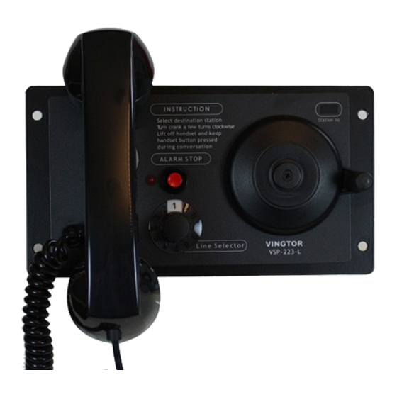
Page 19: Vsp-223-L
8.5 VSP-223-L A100K10873 VSP 12-Way Batteryless Telephone System Technical Manual... - Page 20 Zenitel and its subsidiaries assume no responsibility for any errors that may appear in this publication, or for damages arising from the information therein. VINGTOR-STENTOFON products are developed and marketed by Zenitel. The company’s Quality Assurance System is certified to meet the requirements in NS-EN ISO 9001. Zenitel reserves the right to modify designs and alter specifications without notice.
Need help?
Do you have a question about the Vingtor Stentofon VSP 12-Way and is the answer not in the manual?
Questions and answers