Table of Contents
Advertisement
Quick Links
Installation, Operation and Maintenance Manual
Please read and save these instructions for future reference. Read carefully before attempting to assemble, install,
operate or maintain the product described. Protect yourself and others by observing all safety information. Failure
to comply with these instructions will result in voiding of the product warranty and may result in personal injury
and/or property damage.
IMPORTANT: VCFI fans must be installed with the supplied CAT-5e communication cable or shielded CAT-5e
(by others) that complies with the following specifications. Cable must be twisted pair, shielded 26 ga. CAT-5e
cable with a drain wire and must be compliant with ISO 11801. Cable must use shielded RJ45 connectors with
a soldered drain and wiring configuration must follow EIA/TIA T568B wiring pinout. Individual CAT-5e cable
lengths must not exceed 200 ft. in order to prevent network communication issues.
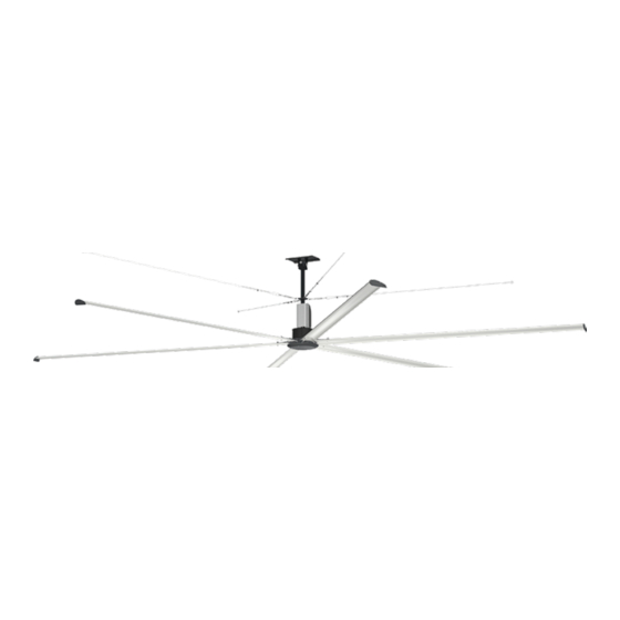
Models VCFI-3 and VCFI-6 are the ideal choice for providing year-round comfort in air circulation and destratification
applications. Featuring an aerodynamic, extruded aluminum airfoil design and a high efficiency direct drive motor,
model VCFI delivers maximum airflow at a fraction of the operating cost of other HVLS fans. And, with its universal
ceiling mount, the VCFI fan is the easiest HVLS fan to install in the market!
General Safety Information
IMPORTANT: To reduce the risk of fire, electric shock,
or injury to persons, Model VCFI fans must be installed
with a mount assembly, motor assembly and airfoils that
are marked (on their cartons) to indicate suitability with
this model. Other mounts, motors, and airfoils cannot
be substituted.
WARNING
To reduce the risk of fire, electric shock, or injury to
persons, observe the following:
1. Use this unit only in the manner intended by the
manufacturer. If you have questions, contact the
manufacturer.
2. Before servicing or cleaning unit, switch
power off at service panel and lock the service
disconnecting means to prevent power from
being switched on accidentally. When the service
disconnecting means cannot be locked, securely
fasten a prominent warning device, such as a tag,
to the service panel.
High Volume, Low Speed Ceiling Fans
WARNING
To reduce the risk of fire, electric shock, or injury to
persons, observe the following:
1. Installation work and electrical wiring must be
done by qualified person(s) in accordance with all
applicable codes and standards, including fire-
rated construction.
2. When cutting or drilling into wall or ceiling, do
not damage electrical wiring and other hidden
utilities.
WARNING
This appliance can be used by children aged from 8
years and above and persons with reduced physical,
sensory or mental capabilities or lack of experience
and knowledge if they have been given supervision or
instruction concerning use of the appliance in a safe
way and understand the hazards involved. Children
shall not play with the appliance. Cleaning and user
maintenance shall not be made by children without
supervision.
High Volume, Low Speed Ceiling Fans
Document 483907
Model VCFI
1
Advertisement
Table of Contents

Related Manuals for VENCO VCFI Series


Summary of Contents for VENCO VCFI Series
- Page 1 Document 483907 Model VCFI High Volume, Low Speed Ceiling Fans Installation, Operation and Maintenance Manual Please read and save these instructions for future reference. Read carefully before attempting to assemble, install, operate or maintain the product described. Protect yourself and others by observing all safety information. Failure to comply with these instructions will result in voiding of the product warranty and may result in personal injury and/or property damage.
- Page 2 4. Do not allow the power cable to kink or come in AVERTISSEMENT contact with oil, grease, hot surfaces or chemicals. Pour réduire le risque d’incendie, de choc électrique Replace cord immediately if damaged. ou de blessure corporelle, respecter ce qui suit : 5.
-
Page 3: Removing From Storage
Storage Inspection & Maintenance During Storage Fans are protected against damage during shipment. If While in storage, inspect fans once per month. Keep a the unit cannot be installed and operated immediately, record of inspection and maintenance performed. precautions need to be taken to prevent deterioration of If moisture or dirt accumulations are found on parts, the unit during storage. - Page 4 so that the tips of the airfoils are a minimum of 3 ft. VCFI-3 VCFI-6 away from the furthest point that a person could Fan Size reach or otherwise come in contact, to prevent *Max. Fan Max Torque *Max. Fan Max. Torque (ft.) Weight (lbs) (ft∙lbf)
-
Page 5: Fan Components
Fan Components NOTE: Additional parts (provided by others) may be Verify that all of the following parts and hardware have been received prior to beginning installation. required to complete the fan installation, including ® Contact your local representative or the manufacturer if additional wiring, steel angle or Unistrut channel, and replacement parts are required. -
Page 6: Required Tools
Optional Fan Components Gripple ® Hardware Kit (Optional) Bag # 915067 Wood Beam Hardware Kit (Optional) Bag # 915429 No. 4 Gripple ® GUY WIRE 20 Ft. Guy Wire (4) No. 4 GRIPPLE ® CONNECTOR Wood Beam Bracket (2) 1/2 in. - 13 GRADE 8 NYLON LOCKNUT Quick Link (8) Turnbuckle (4) -
Page 7: Mounting Installation
Mounting Installation DANGER 1/2 in. - 13 X 2-1/2 in. GRADE 8 HEX BOLT STEEL BEAM Always disconnect, lock and tag power source before installing or servicing. Failure to disconnect power TORQUE TO 45 FT LBF (61.0 N m) source can result in fire, shock or serious injury. DANGER I-BEAM CLAMPING PLATE Pour écarter les risques d’incendie, de choc électrique... - Page 8 Hardware/Tools Needed (Not Included): STRUCTURAL STEEL ANGLES (BY OTHERS) STEEL TRUSS / BAR JOIST • 1/2 in. – 13 Grade 8 Hex Bolt (4), length determined by wood beam thickness • Torque Wrench TORQUE TO 80 FT LBF • 3/4 in. Socket and Wrench (108.5 N m) STRUCTURAL STEEL ANGLES (BY OTHERS)
- Page 9 4. Torque hardware to 80 ft∙lbf (108.5 N∙m). Z-PURLIN TORQUE TO 80 FT LBF (108.5 N m) 5. Turn to page 10 to continue with Motor/Hub to Downtube Installation. Z-PURLIN BRACKET 1/2 in. - 13 x 1-3/4 in. GRADE 8 HEX BOLT Z-Purlin Mounting Kit 1/2 in.
- Page 10 Motor/Hub to Downtube Installation Components required from Bag # 915065: motor/hub assembly to their corresponding female connectors in the downtube. • Motor/Hub Assembly (1) • Rear VFD Cover (1) DOWNTUBE AND MOUNT ASSEMBLY • 3/8 in. – 16 x 2-3/4 in. Grade 8 Hex Bolt (2) •...
- Page 11 8. Plug in the motor power, motor ground, and hall 9. Install rear VFD cover to the back of the VFD using cables as shown. Note that the connectors on the (4) M4-0.7 x 10mm machine screws. Hall and motor power cables only fit in one specific orientation.
- Page 12 Modbus Address Settings - Dipswitch 3 Modbus Position Position Position Position Position Position Address 6, 7, 8 Do Not Modify Safety Retention Cable Installation IMPORTANT: Do not put excessive tension on the 1. From the top of the downtube, pull the safety safety retention cable during installation.
- Page 13 cable clamps in this manner may result in unsafe operating conditions. Refer to drawing below for correct orientation. 5. Pull the dead-end of the safety cable through the steel cable clamps to tighten the cable. LIVE END DEAD END The cable should be pulled taut, 5-1/2 IN.
-
Page 14: Guy Wire Installation
Guy Wire Installation IMPORTANT: Guy wires must be installed 45º to 60º IMPORTANT: Steel cable clamps consist of two parts: from vertical to ensure proper functioning. the u-bolt and the saddle. Steel cable clamps must be installed with the u-bolt over the dead-end of the guy Standard Steel Cable Clamp wire and the saddle over the live-end of the guy wire. - Page 15 ® Gripple Hardware (Optional) 3. Attach all (4) turnbuckles to the guy wire attachment ring located on the downtube using IMPORTANT: Guy wires must be installed 45º to 60º (4) supplied quick links. Pull the loose end of each from vertical to ensure proper functioning. guy wire through the No.
-
Page 16: Hub Plate Installation
Components required from Bag # 915066 OR 854832: 3. With the blade in position on the motor strut, install (2) 5/16 in. 18 x 2 in. hex bolts, (4) 5/16 in. washers, • Airfoil Blade (3 OR 6) and (2) 5/16 in. 18 nylon locknuts per blade as –... -
Page 17: Led Light
LED Light Installation (Optional) LED Light LIGHT COMMUNICATION PLUG 1/4 in. - 20 x 3/4 in. GRADE 5 HEX BOLT Components required from Bag # 915436: (6 PER ASSEMBLY) LIGHT POWER PLUG • Hub Covering Plate (1) • LED Light Assembly (1) •... - Page 18 Wiring and Electrical – Factory Wiring Installation Fire Alarm Relay Installation Communication Wiring & Fan Control Installation The following instructions apply to fans that were supplied with plug-and-play factory wiring. IMPORTANT: VCFI fans must be installed with the supplied CAT-5e communication cable or DANGER shielded CAT-5e (by others) that complies with Always disconnect, lock and tag power source before...
-
Page 19: Power Wiring Installation
Power Wiring Installation c. Repeat step 5b. for subsequent fans until all fans in the chain are connected in series. DANGER d. Follow the “Fan Networking” instructions on Always disconnect, lock and tag power source before page 11 to complete network setup for the fans. installing or servicing. -
Page 20: Pre-Start-Up Checks
Disconnect and Fuse Installation 3. Insert the electrical plug into the receptacle and twist to lock the plug in place. 1. If provided, mount and wire the optional safety 4. Secure any loose power cable to the building disconnect switch outside of the sweep of the fan’s structure to ensure it does not interfere with fan airfoil blades. -
Page 21: Operation
Operation IMPORTANT: If unusual vibration or oscillating of this manual if a problem develops. movement is observed during fan operation, 2. With the system in full operation, measure current immediately discontinue use of the fan and contact the input to the VFD and compare with the FLA ratings manufacturer or a suitably qualified maintenance/repair in the table above to determine if the motor/VFD technician. -
Page 22: Troubleshooting
Troubleshooting Each fan bears a manufacturer’s nameplate with the DANGER fan’s model number and a unique serial number for Disconnect and secure to the ‘OFF’ position all identification. This information will assist the local electrical power to the fan prior to inspection or representative and the manufacturer in providing service servicing. -
Page 23: Modbus Registers
Modbus Registers The VCFI fan’s VFD is configured for Modbus RTU communication as standard. The Modbus register list is for applications where a building management system or field-supplied control are to be used for fan operation. Register Name R/W Retentive Signed Format Range Default Description... -
Page 24: Maintenance Log
_________________________________________________ _________________________________________________ Our Commitment As a result of our commitment to continuous improvement, Venco reserves the right to change specifications without notice. Phone: 1.833.881.0565 • Fax: 715.355.2399 • E-mail: info@vencoproducts.com • Website: www.vencoproducts.com 483907 • VCFI, Rev. 5, June 2020...
Need help?
Do you have a question about the VCFI Series and is the answer not in the manual?
Questions and answers