Table of Contents
Advertisement
Quick Links
Advertisement
Table of Contents

Related Manuals for VENCO VD-EX


Summary of Contents for VENCO VD-EX
- Page 1 INSTALLATION – OPERATION - MAINTENANCE USER MANUAL WALL MOUNTED EXPROOF AXIAL FANS 2019.02 VENCO Havalandırma ve Makina San.ve Tic. A.Ş. 2004. Cad. No:5 45400 OSB Turgutlu – MANİSA / TÜRKİYE Tel: 0090 (236) 332 5070 Fax: 0090 (236) 332 5030 www.venco.com.tr venco@venco.com.tr...
-
Page 2: Table Of Contents
Before operating VENCO branded VD-EX Wall Mounted Axial Type Exproof Fans, please examine carefully the instruction manual and keep it. Do not use devices as a workbench or a storage area. VENCO VD-EX Wall Mounted Axial Type Exproof Fans can only be operated in conditions of intended design and technical specifications. -
Page 3: General Identification Of Device Type And Model
2. GENERAL IDENTIFICATION OF DEVICE TYPE and MODEL VENCO VAX-EX type Exproof Axial fans are the preferred fans for ventilation projects, where there is a risk of explosion, flammability and ignition. It is designed according to EN 14986:2017, EN ISO 80079-36:2016, EN 60079-0:2013 standard. -
Page 4: Technical Specifications
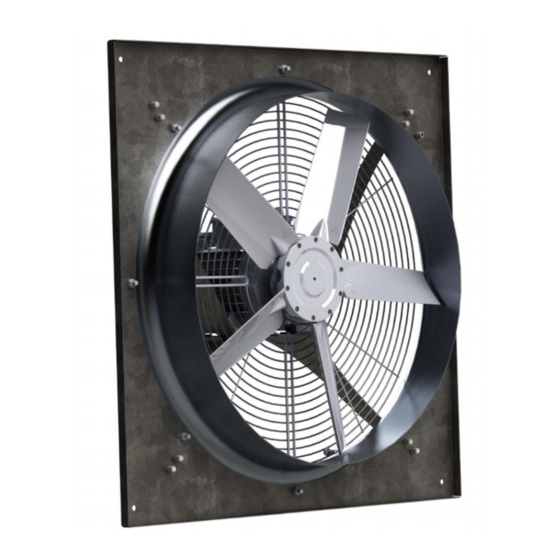
4. TECHNICAL SPECIFICATIONS VENCO VAX-EX Type Wall Mounted Exproof Axial Fans; Certificate Number : Ex Code: Ø Ø Full size from 315 mm to 710 mm diameter 1000 m³/h – 22000 m³/h air flow Hot deep galvanized sheet metal casing ... - Page 5 Sample pictures of the assembled device; VD-EX Fan Diameter Min. (mm) Max. (mm) 1,25 2,25 1,58 2,58 2019.10 4 / 8...
-
Page 6: Operation
ALL ELECTRICAL CONNECTIONS SHALL BE DONE ACCORDING TO EN 60204-1 BY TRAINNED AND AUTHORIZED PERSONNEL. SWITCH THE ENERGY SUPPLY OFF BEFORE YOU BRING ABOUT THE ELECTRICAL CONNECTION OF THE FAN. MAKE SURE THAT THE ENERGY SUPPLY CANNOT BE SWITCHED ON AGAIN PREMATURELY. THE ELECTRICAL CONNECTION MAY ONLY BE CARRIED OUT BY TRAINED PERSONNEL. -
Page 7: Handling & Storage
7. HANDLING & STORAGE Fans are delivered in packages in their boxes according to their models.Transport the fan to the place of assembly in its original packaging. During motor and wire connections mustn’t be damaged. Load and unload the fan carefully, in order to avoid possible damage. Use suitable lifting equipment. The fan should be stored in a safe, clean, dry, vibration free, location. -
Page 8: Fault Detection
In addition to routine maintenance motor bearings will in the longer term require attention. If the motor bearings are greased through extended lubricators, a quality of grease should be periodically applied in accordance with the information on the fan or motor nameplate and/or instructions provided. MAINTENANCE, REPAIR AND REPLACEMENT OF PARTS MUST BE CARRIED OUT BY ATEX TRAINED PERSONNEL. -
Page 9: Annex
ANNEX 11.1 Annex-1: Electrical Wiring Diagrams Motor connection without termic: Motor connection with termic: 2019.10 8 / 8...
Need help?
Do you have a question about the VD-EX and is the answer not in the manual?
Questions and answers