Table of Contents
Advertisement
Quick Links
EN
EN
FR
IT
ES
CDA3000-PLC
System manual
Sub-automation unit
with c-line D
RIVES
VT505W
H1 H2 H3
Parameter
VAL
Hz
stop
start
return
enter
X1
X2
U
V
W
!
ACHTUNG
Kondensatorent-
RB+
ladezeit >3 Min.
Betriebsanleitung
RB
beachten!
WARNING
L-
capacitor disscharge
time >3 minutes.
Pay attention to the
operation manual!
ATTENTION
L1
temps de decharge
du condensteur
L2
>3 min. observer le
mode dèmploi!
L3
VT150W
F6
F7
F8
F9
F10
F1
F2
F3
F4
F5
V
Y
+
PgUp
Z
Info
W
/
7
8
9
X
-
=
M
P
S
PgDn
N
Q
T
Help
4
5
6
O
R
U
D
G
J
E
H
K
1
2
3
F
I
L
.
A
±
Clr
shift
B
0
Esc
C
Space
Enter
X4
X3
Advertisement
Table of Contents

Related Manuals for Lust CDA3000-PLC

Summary of Contents for Lust CDA3000-PLC
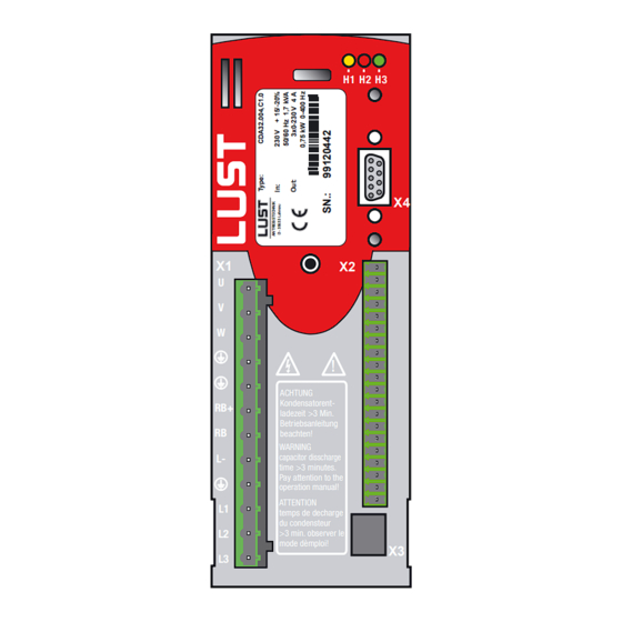
- Page 1 CDA3000-PLC VT150W System manual PgUp Info PgDn Help VT505W ± shift Space Enter H1 H2 H3 Parameter stop start return enter ACHTUNG Kondensatorent- ladezeit >3 Min. Betriebsanleitung beachten! WARNING capacitor disscharge time >3 minutes. Pay attention to the operation manual!
- Page 2 System manual CDA3000-PLC Id.-No.: 0840.12B.1 Stand: 05/.2003 Valid from CDA3000-software version V700.10 We reserve the right to make technical changes.
- Page 3 How to use this guide Directory Introduction System survey Sub-automatisation units Commissioning of PLC-system Order data of system components Sub-automatisation unit with c-line D RIVES...
- Page 4 Pictographs Attention! Faulty operation can cause damage or mal- function of the drive system. Here you will find further comparable applications. The symbol stands for hurdles and barriers, which have to be cleared during realization of the concept. Note: What you have to know, information in short form.
-
Page 5: Table Of Contents
Introduction Thinking in machine sub-automation units ...1-2 Typical machine sub-automation units ....1-4 System survey Software package CDA3000, PLC ......2-2 2.1.1 PLC-Editor ............2-2 2.1.2 PLC-Firmware ............2-11 2.1.3 .............2-20 RIVE ANAGER Operator panels for c-line D ......2-21 RIVES ..........2-31 MART Training ..............2-32 Service-know-how for your projects ....2-34 Sub-automation units Time-controlled luggage belt-drive .......3-2... -
Page 7: Introduction
1 Introduction Due to the increased pressure to reduce costs a new slogan is born in the automation industry. Sub-automation unit - a catchword, which will be used more and more. What is the difference between this solution and others, what are the advantages? This manual clears these and other questions. -
Page 8: Thinking In Machine Sub-Automation Units
1 Introduction Thinking in Thinking in machine sub-automation units requires in the drive units a machine sub- free-programmable core inside, named PLC. Because the contribution to the solution of sub-automation units depends more and more on the flexi- automation units bility of the PLC-user plattform within the drive system. - Page 9 1 Introduction Special at this solution is that the sub-automation unit can be used in other machine types, requiring the same sub-automation unit, without changing the program. picture 1.2 sub-automation unit - drill unit Coupling of sub-automation units to one „function unit“ allows the co-ordi- nation of complex procedures.
-
Page 10: Typical Machine Sub-Automation Units
1 Introduction The complete automatic process is clearly structured resp. is divided in closed machine sub-automation units. Sub-automation units, allowing unitizing of machine types and having a high reusability. Serial commis- sioning can be made without special knowledge or PC, simply via S MART - plug-in, load and run. -
Page 11: System Survey
2 System survey The system consists of the following components: • Drive CDA3000 with accessories and option modules • Software package CDA3000-PLC • Different operator panels with accessories VT150W PgUp Info Help PgDn Programming system for VT505W Operator-Panels Help ±... -
Page 12: Plc-Editor
2 System survey Software pak- The software package CDA3000-PLC consists of three parts: kage CDA3000, • PLC-program editor on CD-ROM. The PLC-editor is additionally to the D RIVE ANAGER On CD-ROM you will find this system manual as well as PLC and device standard software. - Page 13 2 System survey The PLC-program editor offers the following functions: • Program production − Editor for program production − Generating a text declaration file <project name>.txt for varia- bles to show application specific texts in the D RIVE ANAGER − Syntax check of command code −...
- Page 14 2 System survey PLC-Program process A program is divided in two parts: 1. Text declaration for used variables, flags, counter and timer 2. PLC-program The Text declaration is for marking of used variables, counters and timers in the PLC-program with the application specific function. A text file will be generated out of the text declaration, evaluated in the D RIVE , shows the parameters with application specific texts.
- Page 15 The file <Project name>.txt will be copied in the D RIVE file „LUST DriveManager\firmdata\<Project name>.txt“. This NAGER file is only available on the PC, generated this program resp. loaded the source code in the drive controller.
- Page 16 2 System survey There are 3 ways to open an available PLC-program: • Double-click on file *.plc. Then D opens and it starts RIVE ANAGER the PLC-editor and opens the program. • Opening via D menu „File/Open/PLC-process program RIVE ANAGER ...“...
- Page 17 2 System survey PLC-command syntax Comm Operand Note Jump command Ny/END Absolute jump (Ippi = 0/1) Ny/END Condition of input (Oppi = 0/1) Ny/END Condition of output (Mxxx = 0/1, = != Myyy) Ny/END Condition of flag (Mxxx & | ^ Ippi) Ny/END Logical link flag-input (Mxxx &...
- Page 18 2 System survey Comm Operand Note PARA[n, i], PARA[n], Set parameter PARA[Hxxx,Hyyy], PARA[Hxxx] = Hyyy, Fyyy BRKPT = 0 Deactivate brakepoint logic BRKPT = 1 Activate brakepoint logic Read variables with image of output Hxxx = OUTPUT, INPUT resp. input Hxxx, Fxxx = ACTFRQ Read actual frequency [Hz] Hxxx, Fxxx = ACTSPEED...
- Page 19 2 System survey Comm Operand Note Mxxx = STA_ACTIV Motor/Control active (1) Mxxx = STA_LIMIT Limitation (1) Mxxx = STA_REF Reference reached (1) Condition brake Mxxx = STA_BRAKE (1 -> Brake active) Mxxx = STA_OFF Condition de-energized (1) Mxxx = STA_C_RDY Condition control ready (1) Mxxx = STA_WUV Warning undervoltage (1)
- Page 20 2 System survey Comm Operand Note Go relative by value Hxxx and wait W R Hxxx for program processing until target position is reached. Go absolutely by value of Hxxx (pro- A Hxxx gram processing continuous) Go relatively by value of Hxxx (pro- A Hxxx gram processing continuous) Referencing to 0 (reference position...
-
Page 21: Plc-Firmware
2 System survey 2.1.2 PLC-Firmware Firmware CDA3000-PLC with software version number V700.xx is suita- PLC-functionality ble for the frequency inverter CDA3000. It contains a routine for sequen- tial processing of a user-programmed procedure. Number of programs in drive memory: Number of commandlines per program:... - Page 22 2 System survey PLC-Parameters All PLC-control commands are mapped via parameters. They are subject to the already known data set handling of CDA3000. The parameters can be processed via D in the PLC-function window (s. picture RIVE ANAGER 2.5). New ist, that the whole PLC-program is saved as machine code in two parameters.
- Page 23 2 System survey Para- Description meters Interrupt program at line x (Breakpoint). 455- Program will be interrupted at line, mentioned in PLCBN; parameter 450-PLCST PLCBN is going to status BRKPT. Restart of program with 450-PLCST=GO(1) 461- Flag (0/1) PLC_M Access to process program M000...M255 Integer variables (32 bit) Value range from 2 to 2...
- Page 24 2 System survey An easy setting of the a.m. parameters allows the PLC-function window (expanded main window -> PLC or via „basic settings/PLC“ according to selected PLC-preset-solution): picture 2.5 D - PLC-function window RIVE ANAGER 2-14 Sub-automatisation unit with c-line D RIVES...
- Page 25 2 System survey Pre-set solutions Special pre-set solutions are included in the fimware to optimize parame- ter setting of PLC-applications: PLC_1 - PLC-start via terminal, analog reference & fixed fre- quency Function: • Analog speed pre-set for two rotation directions via ISA0 •...
- Page 26 2 System survey • All further I/O’s are available at the PLC-process program. Des. Des. ISD01 Ready message OSD02/14 ISD00 OSD02/11 ENPO ENPO Power stage hardware OSD02/12 enable +24 V DGND +24 V OSD01 OSA00 OSD00 AGND DGND ISA01 +24 V ISA00 ISD03 +10 V Ref.
- Page 27 2 System survey PLC_3 PLC-position control Function: • Position control with PLC-program and control via inputs ISD01 (start positioning - reference 2) and ISA01 (start homing mode) • Control mode FOR • Encoder evaluation via ISD02/03 • Motor control via input ISD00 •...
- Page 28 2 System survey Switch-on/off the position controller via the following commands: N010 SET PCTRL = 1 ; Activate position controller N020 SET PCTRL = 0 ; Deactivate position controller The P-gain 819-PCG of the position controller is adjustable by the (Function window „basic setting“) or via parameter RIVE ANAGER...
- Page 29 2 System survey Error Description Internal error: No code available, program instructions not executable or jump to unused address. Error occurs during loading of process program, if there is still a process E-PLC 216 program is running in the controller and the new program contains other line numbers.
-
Page 30: Drive Manager
RIVE ANAGER can be set with each D -version from V3.20. With the RIVE ANAGER a serial commissioning of the CDA3000-PLC is possible RIVE ANAGER with only one device data set. Condition is an installed D for working with PLC-functiona-... -
Page 31: Operator Panels For C-Line Drives
2 System survey Operator panels With the graduated raw of operator panels high-quality, efficient, multiple use products are available for the system. They guarantee a high-opera- for c-line D RIVES ting comfort and a high-functionality and are equipped with an attractive design, too. - Page 32 2 System survey Further displays as well as customized operator panels are available upon request. operator panels can be used for operating and parameter setting of drive controllers of c-line Drives: • CDA3000 (Standard, HF, PLC) • CDD3000 • CTC3000 Interfaces The operator panels are available with serial L Interface RS232 or...
- Page 33 2 System survey The CAN -interface of operator panels has a master slave structure open (s. picture 2.12). Master Slave Adress Adress Adress Adress picture 2.12 CAN -network with operator panel open It is the job of the operator panels (Master) to initialise and to reconfigure the drive controllers (Slaves);...
- Page 34 2 System survey Article code of panel: Characteristics of panel: VT050 00000N VT050 000CNN Serial port MSP (25 pin female) RS232/RS422/RS485/TTY 20 mA Serial port ASP-8 ( pin female) RS232 Networks Integrated open Characteristics Project-languages Password-level /Bit-Password - / 8 bit Pages/pages-help 127 / 127 Variables per page...
- Page 35 2 System survey Mounting frame Technical data VT150W Article code of panel: Characteristics of panel: VT150W 00000N VT150W 000CNN Display Type Text LCD Background lighting Lines and characters 4 x 20 Representional format [mm] 70,4 x 20,8 Character matrix in text mode [Pixel] 5 x 7 Size of characters [mm] 2,95 x 4,75...
- Page 36 2 System survey Article code of panel: Characteristics of panel: VT150W 00000N VT150W 000CNN Depending on size of project Dynamic texts memory ISA-Alarms/Information messages - / 1024 Alarm buffer Recipes Dimensions Outer W x H x D [mm] 148 x 188 x 41 Mounting frame W x H [mm] 123 x 175 Technical data...
- Page 37 2 System survey Technical data VT505W Article code of panel: Characteristics of panel: VT505W 00000N VT505W 000CNN Display Type Graphic, LCD 4 blue levels STN Touch Screen Matrix 20 x 16 Background lighting CCFL-tube Lifetime [hours] 15000 Resolution 320 x 240 (5,6“) LInes and characters 16x40 / 8x20 / 4x10 Representional format [mm]...
- Page 38 2 System survey Article code of panel: Characteristics of panel: VT505W 00000N VT505W 000CNN Dimensions Outer W x H x D [mm] 210 x 158 x 54 Mounting frame W x H [mm] 198 x 148 Technical data Power supply 24 Vdc (18 ..
- Page 39 2 System survey Technical data VT155W Article code of panel: Characteristics of panel: VT155W 00000N VT155W 000CNN Display Type Graphic, LCD 4 grey levels STN Touch Screen Analog/20x8 (12x16 pixel) Background lighting Resolution 240x128 pixel Lines and characters 16x40 / 8x20 / 4x10 Representional format [mm] 94,5x54,5 Character matrix in text mode [Pixel]...
- Page 40 2 System survey Article code of panel: Characteristics of panel: VT155W 00000N VT155W 000CNN Dimensions Outer W x H x D [mm] 166 x 100 x 43,6 Mounting frame W x H [mm] 157 x 91 Technical data Power supply 24 Vdc (18 ..
-
Page 41: Smart Card / Key Pad
MART the KP200-XL. Parallel to the already used KP200 we offer the KP200-XL, which has to be ordered with a separate article number. Attention: The CDA3000-PLC-operation with K KP200 and/or SC can cause malfunction and is not allowed. MART 2-31... - Page 42 2 System survey Training To introduce the CDA3000-PLC system we offer different trainings. Trai- nings methods are lectures, discussions, demonstrations and practical examples. Training how to program CDA3000-PLC Target: Learning how to handle and program the CDA- PLC software Contents: •...
- Page 43 2 System survey Handling and programming of operator panels Target: Learning how to handle and program Lust-opera- tor panels Contents: • Survey of operator panel components • Characteristics and efficiency of operator panels • Connection of operator panels with the drive controller •...
-
Page 44: Service-Know-How For Your Projects
2 System survey Service-know- Use the know-how of our qualified application engineers. Get decisive advantages to realize efficient sub-automation units with our experience. how for your Solutions, made exactly for your requirements, your demands. projects Compatibility from the beginning: • Projectmanagement −... -
Page 45: Sub-Automation Units
3 Sub-automation units By the mentioned examples in this chapter it deals only with programming exercises for the CDA3000-PLC. Neither the conceptional formulation nor the solutions are checked under safety specifications. The examples show which solutions are possible with integrated sequence control and how a typical program looks like. -
Page 46: Time-Controlled Luggage Belt-Drive
3 Sub-automation units Time-control- Description of the function led luggage If the luggage interrupts the light beam of the light-barrier L1, the con- belt-drive veyor belt FB starts. Max. conveyor speed will be pre-selected via poten- tiometer P1. Cycle length of conveyor FB will be set by means of potentiometer P2. If the time set with potentiometer F2 is passed, the inverter M1, FU1 will be switched-off and the belt runs off. - Page 47 3 Sub-automation units Process program ; Process programme for CDA-PLC, example luggage belt-drive ;Initialisation ;Reference setpoint via analog input ISA0 with caling in the device parameters %TEXT(luggage belt) DEF H000=max_cycle length DEF H001=auxiliary variable DEF H002=analog input %P00 N010 SET H000=20000; max.
-
Page 48: Drill Feed Unit
3 Sub-automation units Drill feed unit The drilling appliance consists of a drilling spindle, feed unit and conveyor unit. In the following we like to explain the sub-automation unit „drilling“ and with it spindle and feeding drive. Basic position The drilling unit is in basic position, if •... - Page 49 3 Sub-automation units Technology scheme Help VT50 Info Shift CDA3000,HF CDA3000 + PLC picture4.2 Drill feed unit Process program ;Program example feed unit ;Inputs: ;M001=Start feed ;IS01=Pre-stop opener ;IS02=Upper limit switch opener ;IS03=Lower limit switch closer %TEXT (feed) DEF H000 = Reference_0 DEF H001 = Timer_1 DEF M002 = Initialisation DEF H002 = Quick-jog frequency...
- Page 50 3 Sub-automation units ; Process program for CDA-PLC %P00 N005 SET H000=0; Reference 0 N010 SET H001=1000; Value for timer 1 N015 JMP (M002=1) N031; Jump over initialising N020 SET H002=70; Reference feed Hz N030 SET H003=20; Slow-jog N031 SET H004=200; Waiting time working point N032 SET M002=1 N040 SET H010=H002;...
-
Page 51: Shredder With Overload Detection
3 Sub-automation units Shredder with Shredder (hacking machines) are used in various applications, for example in the food industry, construction industry or in offices. Fre- overload detec- quently, problems during this process are caused by blocking of the drive. tion The example shows a shredder with overload detection and automatic free-running (back-off) of the roller at blocking. - Page 52 3 Sub-automation units Technology scheme VT505W CDA3000 + PLC picture4.3 Shredder with overload detection Process program ; Process program for CDA shredder ; Inputs ; IS00 - Start control ; IS01 - Start process program ;Ausgänge ; OS00 - Warning overload ;...
- Page 53 3 Sub-automation units %P00 ;Init N005 SET H001 = 500; Reaction time at overload (ms), Z000 N010 SET H002 = 500; Break time at overload (ms) N015 SET H003 = 3000; Reversing time (ms) N020 SET H004 = 20000; Timer repeats reverse N025 SET H005 = 0;...
- Page 54 3 Sub-automation units ; IS02 - Stop ; IS03 - Fault reset ; outputs ; OS00 - c_rdy ; OS01 - Reference reached ; OS02 - Warning current limit %TEXT(shredder) DEF H000 = Value timer reverse DEF H001 = Value timer repeat DEF H002 = Max repeat DEF H003 = Repeat DEF M000 = STA_WIS...
-
Page 55: Unwinder For Wire
3 Sub-automation units N200 SET ENCTRL=1; Enable control N201 SET REFFRQ = F001; Start reverse N210 JMP (IS02=1) N030; Stop required N220 JMP N210 ;End of program Further typical applications are block-protection controls for mixing plants, mills and shredder. Unwinder for The unwinding process, described herein, supplies materials to a dry or wet wire drawing machine. - Page 56 3 Sub-automation units Technology scheme picture4.4 Unwinder for wire Process program ; Process program for CDA-PLC, unwinder ; (Winder with dancer control) ;Dancer control via process controller in firmware %TEXT(Winder) DEF H001=Threshold value DEF H002=Waiting time DEF H000=Analog value DEF M001=Warning_current %P00 ;Initialising N010 SET H001=10;...
-
Page 57: Diameter Depending Speed Control
3 Sub-automation units ;Set-up mode N100 SET ENCTRL=1; Release control N110 WAIT H002; Waiting time start N115 SET M001=STA_WIS; Threshold apparent current exceeded? N120 JMP (IS02=0) N020; SEt-up mode interrupted N125 JMP (M001=0) N115; Detect load surge? N130 SET ENCTRL=0; Control off N140 JMP N020 Further typical applications are warbler and dancer controls for winders. - Page 58 3 Sub-automation units Technology scheme ω CDA3000 + PLC ω picture4.5 Diameter-depending speed control Process program ; Process program for CDA-PLC polishing disc ; Information: ; Speed reference via ISA0, with the following customer-specific ; settings: 0V = 10m/s 10V = 34,5m/s ->...
-
Page 59: Simple Positioning Drive With Plc_3
3 Sub-automation units N010 SET F000=PARA[416]; Call for analog value 0 N015 SET F000*2.45; Scaling in m/s N020 SET F001=F000 N021 SET F001+10; Reference in m/s +Offset 10m/s N022 SET F002=F001; Save reference N030 SET F003=PARA[417]; Call for analog value 1 N035 SET F003*0.128;... - Page 60 3 Sub-automation units Description of the function If the material is on the carriage as well as reference positions 1 and 2 are set via operator panel OP homing can be start via button b1. After successful homing the carriage runs automatically in the rest position 1. Via button b2 the feed to position 2 can be actuated.
- Page 61 3 Sub-automation units ;----------------------------------------------- %P00 ; Initialisation of reference position ; deactivated -> reference positions should not set at every ; start of motor control ; N010 SET H000 = 0; ; N020 SET H001 = 655360; 10 U * 65536 Inkr. ;...
- Page 62 3 Sub-automation units 3-18 Sub-automatisation unit with c-line D RIVES...
-
Page 63: Commissioning Of Plc-System
4 Commissioning of PLC-system 4 Commissioning of PLC-system The following commissionings are described in this chapter: • First commissioning of CDA3000 with PLC-firmware • First commissioning of operator panels at the drive controller The serial commissioning of a frequency inverter with PLC-function is identically with the standard serial commissioning. - Page 64 V3.20-98) copy the D -text files in the D RIVE ANAGER RIVE ANAGER file (C:\program files\Lust Antriebstechnik GmbH): - 3_700_*.pit to „Lust DriveManager\language\001\“ - 3000_ERR.txt to „Lust DriveManager\language\001\“ - 3_700_*.mcw to „Lust DriveManager\firmdata\“ Install the PLC-software on the frequency inverter via menu „Extras/ Load device software“.
- Page 65 4 Commissioning of PLC-system 7. Programming of PLC-functions Select „PLC...“ in the main windows of the D . With this RIVE ANAGER function mask all functions and terms of the PLC can be program- med and tested. picture 4.7 PLC-main window 8.
-
Page 66: First Commissioning Of Operator Panels
VTWIN software on your PC. 4.2.1 Configuration of 1. Installation of RS232-driver for LustBus-protocol RS232-interface If the VTWIN software does not include the Lust-specific software driver for communication via serial RS232-interface (e. G. V4.50 or V4.64), follow the stated steps: - Close VTWIN application - Extract the driver package *.zip. - Page 67 Open directory „MOTOR DRIVE/LUST“ in component window. Draw the icon of drive controller „c-line Drive“ to the interface-icon (MSP or ASP) in the project window. If Lust directory is missing please install the driver as described in 1.). Now the drive is physically connected with the operator panel.
-
Page 68: Configuration Of Can Open -Network
4 Commissioning of PLC-system 4.2.2 Configuration of Conditions for bus-operation: -net- • Drive is equiped with CAN-module (CAN -protocol) open open work • Drive is connected with the operator panel via CAN-Bus • Parameters of the fieldbus interface are set correctly in the connec- ted drive (e.g. - Page 69 4 Commissioning of PLC-system 4. Setting the Baud rate of CAN -network open Open double-click icon interface (FIELD NETWORK (CAN)) the window „port properties“ and set the Baud rate to the requested speed. Please note that the adjustment of the baudrate has to be set in the drive as well.
- Page 70 4 Commissioning of PLC-system Sub-automatisation unit with c-line D RIVES...
- Page 71 Order codes for PLC-software package Order designation Short description Article no. CD-ROM incl. - PLC-Program editor - PLC-Training program PLC-Editor 0842.V11.1 - System manual CDA3000-PLC - Firmware CDA3000-PLC - Licence PLC-Editor DriveManager full version on CD- DRIVEMANAGER V3.20 0842.V08.2 DriveManager-180-days-testver- DRIVEMANAGER V3.20, TEST 0842.V09.2...
- Page 72 5 Order data of system components Order codes for Operator Panel and accessories Bestell- Kurzbeschreibung Artikelnummer bezeichnung VT050 00000N operator panel VT50 (RS232) 1002.0001.0 operator panel VT50 (CAN VT050 000CNN 1002.0002.0 open VT150W 00000N operator panel VT150 (RS232) 1002.0003.0 operator panel VT150 (CAN VT150W 000CNN 1002.0004.0 open...
- Page 73 5 Order data of system components Order codes for trainings and services Order designation Explanation Net price 8 hours incl. post-processing without PLC-Projectmanagement on request travel costs 8 hours incl. post-processing without PLC-Engineering on request travel costs 8 hours incl. post-processing without PLC-Software producing on request travel costs...
- Page 74 5 Order data of system components Sub-automatisation unit with c-line D RIVES...
- Page 76 Lust Antriebstechnik GmbH Gewerbestrasse 5-9 • D-35633 Lahnau Tel. 0 64 41 / 9 66-0 • Fax 0 64 41 / 9 66-137 Internet: http://www.lust-tec.de • e-mail: info@lust-tec.de ID no.: 0840.12B.1 • 05/2003 Technische Änderungen vorbehalten. We reserve the right to make technical changes.
Need help?
Do you have a question about the CDA3000-PLC and is the answer not in the manual?
Questions and answers