Table of Contents
Advertisement
Quick Links
13 SEER Single- -Package Dual Fuel System with
For your convenience, please record the model and serial numbers of your new equipment in the spaces
provided. This information, along with the installation data and dealer contact information, will be helpful
should your system require maintenance or service.
UNIT INFORMATION
Model # _____________________________________
Serial # ______________________________________
ACCESSORIES (List type of model #)
_____________________________________________
_____________________________________________
_____________________________________________
Our products are designed, tested and built in accordance with DOE standardized procedures; however, actual operating results and
efficiencies may vary based on manufacturing and supplier tolerances, equipment configuration, operating conditions and installation
practices.
OWNER'S MANUAL
R- -410A Refrigerant Three Phase
2 1/2 to 5 Nominal Tons
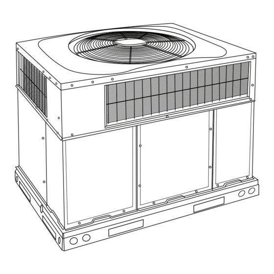
PDD3
Fig. 1 - - Unit PDD3
NOTE TO EQUIPMENT OWNER:
NOTE TO INSTALLER:
This manual must be left with the equipment owner.
Specifications are subject to change without notice.
INSTALLATION INFORMATION
Date Installed________________________________
DEALERSHIP CONTACT INFORMATION
Company Name_______________________________
Address______________________________________
_____________________________________________
Phone Number _______________________________
Technician Name _____________________________
_____________________________________________
A09034
51802230301
09/2016
Advertisement
Table of Contents

Subscribe to Our Youtube Channel
Related Manuals for Carrier PDD3


Summary of Contents for Carrier PDD3
- Page 1 2 1/2 to 5 Nominal Tons PDD3 A09034 Fig. 1 - - Unit PDD3 NOTE TO EQUIPMENT OWNER: For your convenience, please record the model and serial numbers of your new equipment in the spaces provided. This information, along with the installation data and dealer contact information, will be helpful should your system require maintenance or service.
-
Page 2: Safety Considerations
SAFETY CONSIDERATIONS CAUTION Installation and servicing of this equipment can be hazardous due to mechanical and electrical components. Only trained and CUT HAZARD qualified personnel should install, repair, or service this equipment. Failure to follow this caution may result in personal injury. Untrained personnel can perform basic maintenance functions such as cleaning and replacing air filters. -
Page 3: Unit Introduction
burners do not light within 15 minutes of the initial call for CAUTION heat, there is a lockout. 11. Set the temperature selector on room thermostat to desired setting. CUT HAZARD WARNING Failure to follow this caution may result in personal injury. When removing access panels or performing maintenance functions inside your unit, be aware of sharp sheet metal FIRE AND EXPLOSION HAZARD... -
Page 4: Operating Your Unit
4. Remove the control access panel. (See Fig. 2.) MODE control. Refer to your thermostat owner’s manual for more information. 5. Move the selector switch on the internal gas valve to the OFF position. To better protect your investment and to eliminate unnecessary service calls, familiarize yourself with the following facts: 6. - Page 5 MAIN STEP 1 STEP 2 STEP 3 STEP 5 STEP 4 STEP 6 STEP 7 MAIN STEP 8 STEP 9 STEP 10 A07662 Fig. 4 - - To Start Unit Gas Heat 51802230301 Specifications are subject to change without notice.
- Page 6 MAIN STEP 1 STEP 2 STEP 3 STEP 4 STEP 5 STEP 6 A07663 Fig. 5 - - To Shut Off Unit Gas Heat MAIN STEP 2 STEP 4 & 5 STEP 1 STEP 3 A09194 Fig. 6 - - To Start Unit Electric Cooling 51802230301 Specifications are subject to change without notice.
-
Page 7: Maintenance And Service
MAIN STEP 1 STEP 2 STEP 3 A07797 Fig. 7 - - To Shut Off Unit Electric Cooling Defrost Mode WARNING When your heat pump is providing heat to your home or office and the outdoor temperature drops below 45F (7.2C), moisture may FIRE, EXPLOSION, ELECTRICAL SHOCK AND begin to freeze on the surface of the coil. - Page 8 To replace or inspect filters in accessory filter rack (See Fig. 2): 1. Remove the filter access panel using a 5/16- -in. nut driver. 2. Remove the filter(s) by pulling it out of the unit. If the filter(s) is dirty, clean or replace with a new one. When installing the new filter(s), note the direction of the airflow arrows on the filter frame, which should be pointing at the indoor coil.
-
Page 9: Refrigerant Circuit
Condenser (Outdoor) Fan CAUTION WARNING BURN HAZARD Failure to follow this caution may result in personal injury. PERSONAL INJURY UNIT DAMAGE HAZARD Components in heating section may be hot after unit has been started up. When observing flame, be careful not to get Failure to follow this warning could result in personal close to or touch heating components. - Page 10 Before you call for service... SYSTEM switch or MODE control is in the COOL or HEAT and not OFF..check for several easily- -solved problems. ( ) If your unit still fails to operate, call your servicing dealer for If insufficient heating or cooling is suspected: troubleshooting and repairs.
Need help?
Do you have a question about the PDD3 and is the answer not in the manual?
Questions and answers