Table of Contents
Advertisement
Quick Links
Advertisement
Table of Contents

Related Manuals for Dometic 9108672221


Summary of Contents for Dometic 9108672221
- Page 1 9100 Series Power Patio Awning Operation Manual .....2 WARNING Cancer and Reproductive Harm www.P65Warnings.ca.gov REVISION C Form No. 3312736.048 11/19 | ©2019 Dometic Corporation...
-
Page 2: Table Of Contents
For curved sides, please see the separate Hardware List in the Dealer Service Manual for the appropriate model. Use these instructions to ensure correct operation of product. Dometic Corporation reserves the right to modify appearances and specifications without notice. TABLE OF CONTENTS INTRODUCTION ..................................2... -
Page 3: Important Safety Instructions
IMPORTANT SAFETY INSTRUCTIONS This manual has safety information and instructions to help ● This product MUST be [installed / serviced] by a you eliminate or reduce the risk of accidents and injuries. qualified service technician. ● Do NOT modify this product in any way. Modifica- Recognize Safety Information tion can be extremely hazardous. -
Page 4: Open Awning
OPEN AWNING Open Awning Verify valance is in correct position, and adjust if necessary. If awning is over-extended, press 1. PINCH HAZARD. Maintain a toggle down (retract) briefly on (fixed/wired) re- horizontal distance of at least 16″ between fully mote awning switch until valance is in correct open awning and any permanent object. -
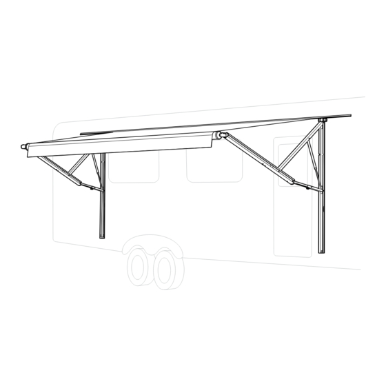
Page 5: Set Awning Position
SET AWNING POSITION Adjust Awning Pitch (Optional) FIG. 4 The FRTA (fabric roller tube assembly) will be lower Top Arm than RV’s awning rail when hardware is fully ex- Assembly tended. This pitch (slope) will help accommodate water runoff. If a steeper pitch is desired, the FRTA must be lowered. -
Page 6: Close Awning
SET AWNING POSITION Loosen adjustable knob on adjustable pitch arm 4. While holding top arm assembly in place, tighten assembly (bottom arm) that’s farthest from entry adjustable knob to set in place. See (FIG. 4). door. See (FIG. 3). FIG. 5 ... -
Page 7: Prepare Awning For Travel
CLOSE AWNING Prepare Awning For Travel 2. Disable awning for travel to service center: a. Close awning and remove fuse for power 1. IMPACT OR CRUSH HAZARD. source to awning. Make sure ignition interlock is working correctly b. Retest ignition interlock. See step (1). before traveling with RV. -
Page 8: Pull Strap Method
CLOSE AWNING MANUALLY (POWER FAILURE) 3. Insert pull strap (provided) into utility slot of FRTA, FIG. 7 and slide to center (of FRTA). See (FIG. 8). FIG. 8 Motor Connector Hardware Connector (2) Screws In Top Casting 4. Connect 16 Gauge (minimum) wire leads (user supplied) to motor connector, and tape in place (with electrical tape). -
Page 9: General Care And Use
A pply a very small dab of VLP (Vinyl Liquid abrasives to clean parts, as their protective sur- Patch) on tip of cotton swab. faces will be damaged. V LP is available from Dometic Cor- poration. Reference part...
Need help?
Do you have a question about the 9108672221 and is the answer not in the manual?
Questions and answers