
Related Manuals for Renishaw TRS2

Summary of Contents for Renishaw TRS2
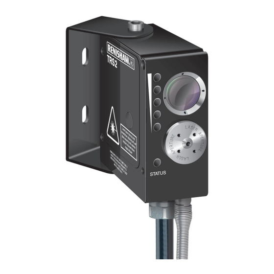
- Page 1 Installation guide TRS2 non-contact broken tool detection system www.renishaw.com/trs2 #renishaw...
- Page 2 Compliance information for this product is available by scanning the QR code or visiting www.renishaw.com/mtpdoc...
-
Page 3: Table Of Contents
Dimensions of hard-wired TRS2 units and laser warning labels . . . . . . . . . . . . . . . . - Page 4 Parts list . . . . . . . . . . . . . . . . . . . . . . . . . . . . . . . . . . . . . . . . . . . . . . . . . . . . . . . . . . . . . . . . . . . . . . . . . .6-1 TRS2 non-contact broken tool detection system...
-
Page 5: Before You Begin
Renishaw office. Renishaw warrants its equipment and software for a limited period (as set out in the Standard Terms and Conditions), provided that they are installed and used exactly as defined in associated Renishaw documentation. -
Page 6: Software Notices
NOTICE TO UNITED STATES GOVERNMENT CONTRACT AND PRIME CONTRACT CUSTOMERS This software is commercial computer software that has been developed by Renishaw exclusively at private expense . Notwithstanding any other lease or licence agreement that may pertain to, or accompany... -
Page 7: Safety
Renishaw product literature, and to ensure that adequate guards and safety interlocks are provided . If the TRS2 unit fails, the output signal may falsely indicate beam not blocked . Do not rely on signals from the TRS2 unit to halt the movement of the machine . -
Page 8: Warnings
• Prevent the laser beam from straying outside of the immediate work area . A laser warning sign/beam terminator is supplied with the TRS2, which may be fixed to the outside of the machine window for this purpose . CAUTION – LASER SAFETY The laser used in the Renishaw TRS2 non-contact broken tool detection system emits visible red light at a wavelength of 670 nm and has a power output of less than 1 mW . -
Page 9: Trs2 Basics
The hard-wired version does not have a connector socket; electrical connections to the machine controller are hard-wired directly to the TRS2 . Both versions of the TRS2 can be adjusted to detect a broken tool over the range of 300 mm (11.81 in) to 2 m (78 .74 in) . -
Page 10: Signal Strength Indication
The TRS2 is designed to function over a 300 mm (11 .81 in) to 2 m (78 .74 in) range, although it is optimised for use at 1 m (39 .37 in) or less . At the minimum distance of 300 mm (11 .81 in), the TRS2 can detect a solid centred tool that has a diameter of 0 .2 mm (0 .008 in) or greater . -
Page 11: Dimensions Of Hard-Wired Trs2 Units And Laser Warning Labels
Dimensions of hard-wired TRS2 units and laser warning labels 38 (1 .50) 73 (2 .87) 4 .5 (0 .18) Ø4 .7 (0 .19) 68 (2 .68) Receiver lens Signal TRS2 access strength Labels panel indication Laser aperture Status LED 4 .5 (0 .18) 14 .5 (0 .57) -
Page 12: Dimensions Of Trs2 Units With Connector
51 (2 .01) (1 .10) 107 (4 .21) 73 (2 .87) TRS2 without mounting bracket 153° 41 (1 .61) 14 (0 .55) TRS2 with mounting bracket 122° Dimensions given in mm (in) TRS2 non-contact broken tool detection system: TRS2 basics... -
Page 13: Trs2 Specification
Ø0 .2 mm (0 .008 in) detection Detection range TRS2 adjustable between 300 mm (11 .81 in) and 2 m (78 .74 in) . Factory set to 350 mm (13 .78 in) . Supply voltage 11 Vdc to 30 Vdc... - Page 14 Each TRS2 unit is tested with a Ø0.5 mm (0.02 in), blue finish, HSS jobber drill at a range of 350 mm (13.78 in). Test conditions: dry tool, spinning at 5000 r/min, which must be detected by the TRS2 within 1 second .
-
Page 15: System Installation
. • The tool must be able to move in the Z axis relative to the TRS2 unit, so that tools of different lengths can be checked . •... -
Page 16: Mounting Configurations
Mounting configurations Mount the TRS2 unit on a rigid part of the machine (see the figure below for possible mounting configurations). Tighten the mounting screws as follows: For M6 mounting screws, tighten to 14 Nm (10.30 lbf.ft) using a 10 mm A/F spanner and a 5 mm A/F hex driver . -
Page 17: Air Supply
If it is necessary to switch off the air supply, ensure that the coolant supply is switched off first. The air supply to the TRS2 system must conform to BS ISO 8573-1: air quality of class 1.7.2 and be moisture-free. -
Page 18: Connecting And Purging The Air Supply
Connect the free end of the air pipe into the air preparation pack inlet . Take a length of Ø4 mm air pipe that will connect the air preparation pack outlet to the TRS2 . Cut to length as short as possible to minimise the drop in air pressure . Make a note of this pipe length . - Page 19 TRS2 unit Ø4 mm air pipe Cable conduit Spring cover CAUTION: If it is necessary to switch off the air supply, ensure that the coolant supply is switched off first to prevent contamination of the TRS2 access panel . www.renishaw.com/trs2...
-
Page 20: Air Blast Pack
Air blast pack The air blast pack is an optional device available from Renishaw (see page 6-1, “Parts list”) . It can be used prior to the broken tool detection cycle to clean coolant and swarf from a tool . When checking a tool that is rotating at either 200 r/min or 1000 r/min, it is recommended that the air blast is used for optimum performance . -
Page 21: Electrical Connections
Power supply The TRS2 can draw its power from the CNC machine’s 12 V to 24 V nominal dc supply . Its input voltage range is 11 Vdc to 30 Vdc maximum and it presents a typical load of up to 65 mA at 12 Vdc and up to 43 mA at 24 Vdc. -
Page 22: Setting Up The Trs2 System
Preparation To set the operating range of the TRS2 you will need to change the settings of the receiver focus screw and laser focus screw . If these screws cannot be accessed when the TRS2 unit is mounted in the machine, range setting can be performed off the machine . - Page 23 2 Nm (1 .48 lbf .ft), taking care to ensure the laser focus screw does not move . CAUTION: Do not adjust the laser focus screw with the locking ring tightened . Finally, remove the paper target from the tool . www.renishaw.com/trs2...
-
Page 24: Spindle Speed Selection
Spindle speed selection For a tool to be detected by the TRS2 system, it must be rotating at a fixed speed of 5000 r/min, 1000 r/min or 200 r/min. The required spindle speed must be selected in the macro software. •... - Page 25 (11 .81 in to 78 .74 in) When the TRS2 unit is rear mounted, fit the M6 locking screw and washer to the underside of the unit and tighten to 14 Nm (10 .30 lbf .ft) using a 5 mm A/F hex driver .
-
Page 26: Using The Signal Monitor Function
The signal monitor function is available only on the version of TRS2 that is fitted with a connector. If the operator is unable to see the signal strength indicators on the front of the TRS2, the signal monitor function can be used to monitor the reflected light signal level: Connect the pink (+) and blue (–) wires to a digital voltmeter (DVM). -
Page 27: Maintenance
About cleaning Cleaning may be required if the air to the TRS2 becomes contaminated or if the system is left with the air off when coolant is present . Excessive contamination of the access panel will block the laser beam and prevent the TRS2 from functioning . -
Page 28: Cleaning The System
Cleaning the system CAUTION: Before removing the TRS2 access panel, switch off electrical power to avoid exposure to the laser beam . Make a note of the air supply pressure, then switch off the air supply and power supply . -
Page 29: Replacing The Receiver Lens
Refit the O-ring and TRS2 access panel, ensuring that the O-ring is seated correctly. Tighten the access panel to 2 Nm (1.48 lbf.ft). Spray the solvent cleaner onto the receiver lens surface and clean off using a swab . 10 . Switch on the air supply and set the pressure to the value noted in step 1 . -
Page 30: Fitting A Sapphire Glass Window
Fitting a sapphire glass window If the TRS2 receiver lens is likely to become scratched due to bombardment by swarf, it can be protected by a hard sapphire glass window (for more information, see page 6-1, “Parts list”) . After fitting the sapphire glass window there may be a reduction in the signal level, as displayed by the signal strength indicators . -
Page 31: Maintenance - Air Preparation Pack
Switch on the air supply and set the pressure to the value noted in step 1 . NOTE: Items shown within dotted box A are included in the air filter service pack obtainable from Renishaw (for more information, see page 6-1, “Parts list”) . www.renishaw.com/trs2... - Page 32 TRS2 non-contact broken tool detection system: Maintenance...
-
Page 33: Fault-Finding
Check that the wiring connections are correct . (status LED is not lit). Wrong supply voltage . Check the supply voltage to the TRS2 is correctly set at 11 Vdc to 30 Vdc . Blown fuse. Check that the connections and remove any short circuits . - Page 34 3-9, “Adjusting the receiver focus screw”) . The tool checking position Check that the gap between the TRS2 and and TRS2 are out of range . tool checking position is between 300 mm (11.81 in) and 2 m (78.74 in). If necessary, edit the tool checking position or re-position the TRS2 .
-
Page 35: Parts List
Description TRS2 hard-wired unit A-5450-0400 TRS2 unit with Ø4 .85 mm (0 .19 in) × 10 m (32 .80 ft) electrical pack (10 m) cable, mounting bracket, pin spanner, machine tool support card and laser warning sign/beam terminator (× 2) . - Page 36 . Cleaning swab P-AD99-0171 Cleaning swab for cleaning the optics (× 50) . Publications. These can be downloaded from our website at www.renishaw.com. Software programs H-2000-2298 Data sheet: Probe software for machines tools – programs and and features features .
- Page 37 TARGET TO AID ALIGNMENT TARGET TO AID ALIGNMENT TARGET TO AID ALIGNMENT TARGET TO AID ALIGNMENT...
- Page 38 © 2007–2023 Renishaw plc . All rights reserved . This document may not be copied or reproduced in whole or in part, or transferred to any other media or language by any means, without the prior written permission of Renishaw .
Need help?
Do you have a question about the TRS2 and is the answer not in the manual?
Questions and answers