Advertisement
Quick Links
Advertisement

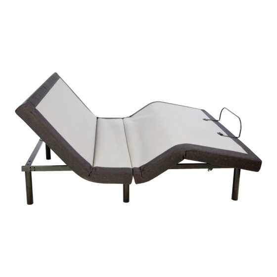
Summary of Contents for GhostBed POWER ADJUSTABLE BASE
- Page 1 Serial No.
- Page 4 Parts List Parts List Parts List All electronics and components that need to be installed are located in boxes under the foundation or All electronics and components that need to be installed are located in boxes under the foundation or All electronics and components that need to be installed are located in boxes under the foundation or attached to the frame.
- Page 5 MODE MODE Head Massage Head Massage Motor Motor...
- Page 6 Installa Installa Note: For safety reasons, lifting of the adjustable bed frame must be performed by two (2) people; and the Note: For safety reasons, lifting of the adjustable bed frame must be performed by two (2) people; and the STEP 1 STEP 1 Lift the folded bed frame unit out of the shipping carton...
- Page 7 Installa Installa Installa STEP 4 STEP 4 The fabric section without the foam goes alongside STEP 4 the USB hub. The fabric section without the foam goes alongside the USB hub. The fabric section without the foam goes alongside the USB hub. STEP 5 STEP 5 Attach the rail with the Velcro so it is smooth and...
- Page 8 Installa Installa STEP 7 STEP 7 Attached top rail to the Velcro strips so it is upright and smooth. Attached top rail to the Velcro strips so it is upright and smooth. STEP 8 STEP 8 Remove all the accessories boxes and the retainer bar from the inside of the unit.
- Page 9 Installa Attaching the bed legs Remove the six (6) bed legs from the accessory box. Hand tighten the legs by threading them clockwise into the pre-threaded holes on the bed frame. NOTE: the legs are 3 pcs and can be separated and attached to the base using 1, 2 or all 3 parts to achieve different heights of the overall base.
- Page 10 Installa Installa Installa...
-
Page 13: Emergency Power Down
Emergency Power Down Your adjustable bed frame comes with a power supply that, when powered with two new 9V batteries, supports the emergency power down feature. If a power failure occurs while the head and/or foot sections are raised, do the following: STEP 1 Install two (2) new 9V batteries in the battery compartment of the power supply. - Page 14 MODE MODE MODE MODE MODE MODE MODE MODE MODE MODE MODE MODE Remote A Remote B MODE Remote A Remote B MODE MODE MODE MODE MODE Remote A Remote B Set Remote B operate both bases too. Set Remote B operate both bases too. Set Remote B operate both bases too.
- Page 19 Parts List Parts List Parts List All electronics and components that need to be installed are located in boxes under the foundation or All electronics and components that need to be installed are located in boxes under the foundation or All electronics and components that need to be installed are located in boxes under the foundation or attached to the frame.
- Page 20 MODE MODE Head Massage Head Massage Motor Motor...
- Page 21 Installa Installa Note: For safety reasons, lifting of the adjustable bed frame must be performed by two (2) people; and the Note: For safety reasons, lifting of the adjustable bed frame must be performed by two (2) people; and the STEP 1 STEP 1 Lift the folded bed frame unit out of the shipping carton...
- Page 22 Installa Installa Installa STEP 4 STEP 4 The fabric section without the foam goes alongside STEP 4 the USB hub. The fabric section without the foam goes alongside the USB hub. The fabric section without the foam goes alongside the USB hub. STEP 5 STEP 5 Attach the rail with the Velcro so it is smooth and...
- Page 23 Installa Installa STEP 7 STEP 7 Attached top rail to the Velcro strips so it is upright and smooth. Attached top rail to the Velcro strips so it is upright and smooth. STEP 8 STEP 8 Remove all the accessories boxes and the retainer bar from the inside of the unit.
- Page 24 Installa Attaching the bed legs Remove the six (6) bed legs from the accessory box. Hand tighten the legs by threading them clockwise into the pre-threaded holes on the bed frame. NOTE: the legs are 3 pcs and can be separated and attached to the base using 1, 2 or all 3 parts to achieve different heights of the overall base.
- Page 25 Installa Installa Installa...
- Page 28 Emergency Power Down Your adjustable bed frame comes with a power supply that, when powered with two new 9V batteries, supports the emergency power down feature. If a power failure occurs while the head and/or foot sections are raised, do the following: STEP 1 Install two (2) new 9V batteries in the battery compartment of the power supply.
- Page 29 MODE MODE MODE MODE MODE MODE MODE MODE MODE MODE MODE MODE MODE Remote A Remote B MODE MODE MODE MODE MODE Remote A Remote B Remote A Remote B Set Remote B operate both bases too. Set Remote B operate both bases too. Set Remote B operate both bases too.

Need help?
Do you have a question about the POWER ADJUSTABLE BASE and is the answer not in the manual?
Questions and answers