
Related Manuals for NKE 90-60-450

Summary of Contents for NKE 90-60-450
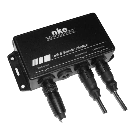
- Page 1 Loch Sounder Interface Product reference : 90-60-450 INSTALLATION GUIDE Zi de Kerandré – Rue Gutemberg – 56700 – HENNEBONT – FRANCE www.nke-marine-electronics.com +33 297 365 685...
- Page 2 TABLE OF CONTENTS PRESENTATION ........................3 TECHNICAL SPECIFICATIONS ................... 4 DIAGNOSTIC FOR 1 LEVEL TROUBLESHOOTING............4 INSTALLATION ........................5 4.1 L ......................5 IST OF ACCESSORIES 4.2 I ....................5 NSTALLATION PRECAUTIONS 4.3 I ............. 5 NSTALLATION OF THE LOCH SOUNDER INTERFACE HOUSING 4.4 C ..................
- Page 3 KNOTS APP WIND A 105- DEGRES DEPTH 10.50 METERS input NMEA NMEA + NMEA - log depth interface 90-60-450 Cable TOPLINE 20-61-001 DATA black 12VDC white connecting box 90-60-417 depth speedomètre Figure 1 IMPORTANT Read this user guide entirely before starting the installation.
- Page 4 TECHNICAL SPECIFICATIONS Power supply : 10 to 16VDC Consumption : 60mA Tightness :IP54 Weight : 160 g Operating temperature : -10°C to +50°C Storage temperature : -20°C to +60°C DIAGNOSTIC FOR 1 LEVEL TROUBLESHOOTING. This chapter can help you rapidly resolve minor problems which do not require the intervention of a specialist.
- Page 5 INSTALLATION 4.1 List of accessories 15 meter bus cable fitted with a connector : 90-60-460 TOPLINE Terminal box : 90-60-121 Cable adapter for old version of depth-finder sensor 90-60-453. Cable adapter for old version of vaned rotor log sensor : 90-60-454 TOPLINE bus connector : 90-60-465.
- Page 6 1.20 BOAT SPEED 23.4 DEPTH Depth log interface 90-60-450 Supply voltage 12Vdc DATA black 12VDC white connecting box90-60-121 Figure 3 : connection to bus TOPLINE If you reduce the length of the bus cable 90-60-460, strip and galvanise the wires before connecting them inside the terminal box.
- Page 7 NOTES _________________________________________________________________ _________________________________________________________________ _________________________________________________________________ _________________________________________________________________ _________________________________________________________________ _________________________________________________________________ _________________________________________________________________ _________________________________________________________________ _________________________________________________________________ _________________________________________________________________ _________________________________________________________________ _________________________________________________________________ _________________________________________________________________ _________________________________________________________________ _________________________________________________________________ _________________________________________________________________ _________________________________________________________________ ______________________________________________________ Loch_Sounder_Interface_um_EN_17_21...
- Page 8 NOTES _________________________________________________________________ _________________________________________________________________ _________________________________________________________________ _________________________________________________________________ _________________________________________________________________ _________________________________________________________________ _________________________________________________________________ _________________________________________________________________ _________________________________________________________________ _________________________________________________________________ _________________________________________________________________ _________________________________________________________________ _________________________________________________________________ _________________________________________________________________ _________________________________________________________________ _________________________________________________________________ _________________________________________________________________ _____________________________________________________ Loch_Sounder_Interface_um_EN_17_21...
Need help?
Do you have a question about the 90-60-450 and is the answer not in the manual?
Questions and answers