Advertisement
Introduction
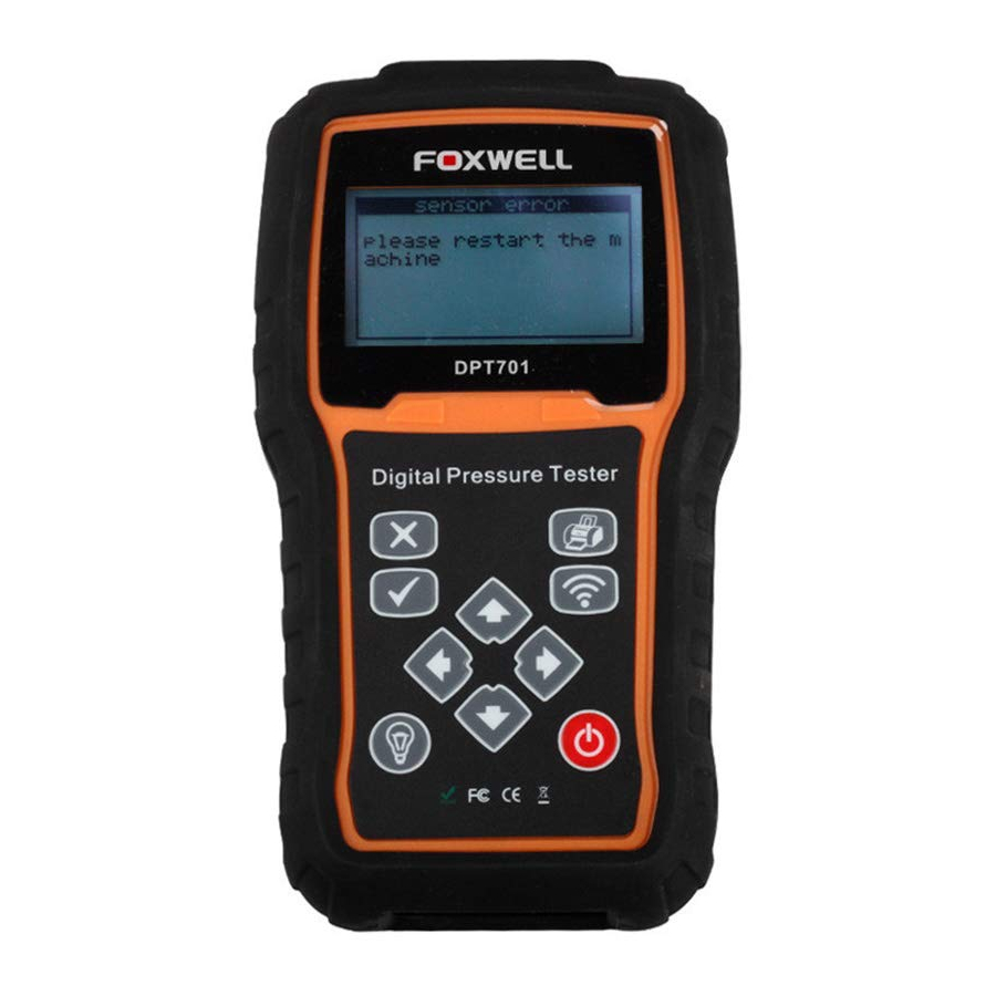
DPT701 is a useful tool to measure fuel pressure and engine compression. It can be used to measure pressure up to 80 bar(1160PSI) for any gas and noncorrosive liquid.
With the tester properly connected to the sensor and powered on, you can use the tester to measure fuel pressure and engine compression; to check the battery, the sensor and the microprocessor automatically; and transfer data to computer for close check and printing with wireless module.
Bold Text
Bold text is used to highlight selectable items such as buttons and menu options.
Example
Press the ENTER key to select.
Symbols and Icons
Solid Spot
Operation tips and lists that apply to specific tool are introduced by a solid spot ●.
Example
When System Setup is selected, a menu that lists all available options displays. Menu options include:
- Languages
- Unit
- Workshop Name saving
Arrow Icon
![]() An arrow icon indicates a procedure.
An arrow icon indicates a procedure.
Example
![]() To change menu language
To change menu language
- Scroll with the arrow keys to highlight Language on the menu.
- Press the ENTER key to select.
Note and Important Message
Note
A NOTE provides helpful information such as additional explanations, tips, and comments.
Example
NOTE
Test results do not necessarily indicate a faulty component or system.
Important
IMPORTANT indicates a situation which, if not avoided, may result in damage to the test equipment or vehicle.
Example

Do not soak keypad as water might find its way into the tester.
Device Descriptions

This section illustrates external features, ports and connectors of the tester.
- LCD Display - shows menus, test results and operation tips.
- Back Key – cancels an action and returns to previous screen or level.
- Printing Key– it's used to send the test result to the printer if needed. With the wireless printing module, the user can print the test data without the action to connect it to a printer.
- OK Key - confirms an action or movement and goes to next level, and saves test data.
- Wireless Receiver Key - is used to send data to a PC using the Foxwell wireless receiver.
- Direction Keys - select an option or show the Max value of the testing pressure..
- LCD Backlight Key – To turn on/off the LCD backlight as users' will in order to save battery power
- Power Switch - turns on/off the scanner and press and hold for 5 seconds for emergency reboots.
- Port for Sensor- Provides a connection between the pressure tester and the sensor.
Do not use solvents such as alcohol to clean keypad or display. Use a mild nonabrasive detergent and a soft cotton cloth.
Accessory Descriptions
This section lists the accessories that go with the tester. If you find any of the following items missing from your package, contact your local dealer for assistance.
- User's Guide
- 80 Bar Sensor
- Wireless PC receiver
- Spare Fuse
- 2X2 Diagnostic Adapter
- CD
- Sealant
- Blower Molding Case
- Bluetooth Adapter
Technical Specifications
Sensor type: Strain gauge technology, amplified and digital temperature compression
Sensor output: Ratiometric, 0.5/4.5 V DC at 5 V DC excitation
Sensor FS.: 80 bar / 1160 psi
Resolution: 0.1 bar / 1psi
Proof pressure: 150% FS
Battery type: 9V
Display: Backlit 64x128 pixels graphic LCD
Data transmission interface: wireless module
Adapters included: 6mm and 8mm
Working Temperature:0 to 60℃ (32 to 140℉)
Storage Temperature:-20 to 70℃ (-4 to 158℉)
Dimensions:190*110*44mm
Getting Started
This section describes how to provide power to the tester and how to program the scanner to meet your specific needs
Providing Power to Device
Before using the tester, make sure to provide power to the tester. The unit operates on 9-volt cell battery
Powered by Cell Battery
The scan tool receives power through a 9 volt cell battery which installed in the back of the tester.
![]() To install the battery
To install the battery
- Prepare a 9 volt lithium battery.
- Install this battery in the back of the tester. Please pay attention to its positive pole and negative pole.
- Press the power switch of the tester to power it on.
Replace Battery (9V)
- If the product does not go on or goes out repeatedly, the power supply battery might be too low.
- To replace the battery, open the rear cover of the instrument to gain access to the battery compartment. Replace the battery with a new 9-volt battery and replace the cover on the back of the instrument.
System Setup
This section illustrates how to program the scanner to meet your specific needs. Options typically include:
- Select the language
- Change measurement unit (Bar or Psi)
- Save the plate number
Note
System Setup settings remain until changes to the existing setups are made.
 To do system setup
- Enter into the setup mode by pressing the OK key as soon as the tester is turned on (within 3 seconds).
Select Language
Selecting Language opens a screen that allows you to choose system language. The tester is set to display English menus by default.
![]() To configure system language
To configure system language
- Scroll with the up and down arrow keys to highlight Language from Setup menu and press the OK key to confirm.
![]()
Sample Language Selection Screen

Select Measurement Unit
After confirming the language, the tester will automatically show the selection of measurement unit. The tester is set to display BAR as default pressure standard.
![]() To select measurement unit
To select measurement unit
- Scroll with the up and down arrow keys to select BAR/PSI from Setup menu and press the OK key to confirm
![]()
Sample Measurement Unit Selection Screen

Save The Plate Number
The Plate Number will be used to send the test data to PC for further checking and printing when the wireless receiver is connected with computer.
![]() To Save The Plate Number
To Save The Plate Number
- Press the data printing key
- Input the plate number with the arrow keys.
Backlight
The backlight can be activated at any time using the backlight key. To deactivate the backlight, press the backlight again. Please note that the backlight needs a lot of battery power; so it should be used only when it is strictly necessary.
Diagnostic Operation
This section illustrates how to measure fuel pressure and engine compression.
Start-up Auto Test
A start-up auto test assures the user that the battery, the sensor and the microprocessor are working properly when the tester is turned on.
![]() To perform Start-up Auto Test
To perform Start-up Auto Test
- Connect the pressure sensor to the pressure tester, then press power on key to turn on the tester. The display will show the welcome message for three seconds.
![]()
Sample Start-up Welcome Screen - A "power on test" will be performed and the battery, sensor, memory and fuse will be tested one by one automatically.
![]()
Sample Battery Test Screen
![]()
Sample Sensor Test Screen
![]()
Sample Memory Test Screen
![]()
Sample Fuse Test Screen - If any one item of the above four is failed, a faulty message will displayed.
![]()
Sample Start-up Auto Test Failed Screen


Diagnostic Function Selection
When "Power on test" is finished successfully, a menu with available service options displays. Menu options typically include
- Oil pressure test
- Petrol compression
- Diesel compression
- 80 Bar manometer
- Petrol inj. system
- Low side common rail
Oil Pressure Test
The oil pressure test allows you to test oil pressure. By default the maximum reading will be shown on the display.
![]() To perform oil pressure test
To perform oil pressure test
- Scroll up and down arrow keys to select Oil pressure test from the option menu and press OK key to confirm.
![]()
Sample Select An Option Menu Screen - The actual reading displayed as the following screen.
![]()
Sample Actual Reading Screen - Using the right arrow key to move between the maximum and actual reading.
![]()
Sample Maximum Reading Screen - Using the Left arrow key to clear the maximum reading.


NOTE
The maximum reading is stored even though the display shows the actual reading.
Petrol Compression Test
Petrol compression and diesel compression belongs to Engine compression test. It allows to you test the actual engine compression.
![]() To perform Petrol compression test:
To perform Petrol compression test:
- Scroll up and down arrow keys to select Petrol compression from the option menu and press OKkey to confirm.
![]()
Sample Select An Option Menu Screen - The petrol compression will be displayed. Scroll up and down arrow keys to select the right cylinder and the maximum reading will be displayed and stored automatically.
![]()
Sample Petrol Compression Reading Screen - Use the left arrow key to clear the reading of the selected cylinder and pressing the right arrow key you can toggle between graphical and text display.
![]()
Sample Graphical Display Screen


NOTE
The graphic bar will represent 0 to 10 bar when you test petrol compression.
Diesel Compression Test
Diesel compression and petrol compression belongs to Engine compression test. It allows to you test the actual engine compression.
![]() To perform Diesel compression test:
To perform Diesel compression test:
- Scroll up and down arrow keys to select Diesel compression from the option menu and press OK key to confirm.
![]()
Sample Select An Option Menu Screen - The diesel compression will be displayed. Scroll up and down arrow keys to select the right cylinder and the maximum reading will be displayed and stored automatically.
![]()
Sample Diesel Compression Screen - Use the left arrow key to clear the reading of the selected cylinder and pressing the right arrow key you can toggle between graphical and text display.
![]()


NOTE The graphic bar will represent 0 to 80 bar when testing diesel compression.
80 Bar Manometer
80 Bar Manometer allows you to test any pressure up to 80 Bar. The actual reading will be shown on the screen by default.
![]() To perform 80 Bar manometer:
To perform 80 Bar manometer:
- Scroll up and down arrow keys to select 80 Bar manometer from the option menu and press OK key to confirm.
![]()
Sample Select An Option Menu Screen - The actual reading will be displayed as following screen.
![]()
Sample Actual Reading Screen - Use the right arrow key to move between the maximum and actual reading.
![]()
Sample Maximum Reading Screen


NOTE
The maximum reading is stored even if the display shows the actual reading and the stored maximum reading can be read by pressing the right arrow key.
Petrol Injection System
Petrol Injec. System allows you to test petrol pressure. The actual reading will be shown on the screen by default.
![]() To perform Petrol Injection System:
To perform Petrol Injection System:
- Scroll up and down arrow keys to select Petrol Injec. System from the option menu and press OK key to confirm.
![]()
Sample Select An Option Menu Screen - The actual reading will be displayed as following screen.
![]()
Sample Petrol Inj. System Actual Reading Screen - Using the right arrow key to move between the maximum and actual reading, using the Left arrow key to clear the maximum reading.
![]()
Sample Petrol Inj. System Maximum Screen


NOTE
The maximum reading is stored even if the display shows the actual reading and the stored maximum reading can be read by pressing the right arrow key.
Common Rail Test - Low Pressure Circuit
This section illustrates how to test low pressure circuit with FOXWELL DPT701, the largest number of failures are produced in the low pressure circuit.
About The Common Rail System
What is the Common Rail System?
The common rail system refers to the fact that all of the fuel injectors are supplied by a common fuel rail which is nothing more than a pressure accumulator where the fuel is stored at high pressure. It is one of the most advanced diesel fuel injection systems.
One of the great advantages of this new system lies in the fact that the nozzles are controlled electronically; so an electronic unit decides what the exact amount of fuel needed by the engine is and sends an electrical signal to the injectors to open the nozzle. At that time the fuel pressure in the common rail passes through the nozzles and goes into the cylinders. The name common rail comes from the fact that the injectors are all connected to a common rail.
The injection system is divided into two distinct parts: the low pressure circuit and the high pressure circuit.
The low pressure circuit is responsible for getting fuel to the high pressure pump in optimal conditions of pressure, filtering etc.
The Structure of the Common Rail Systems
The low pressure circuit consists essentially of: fuel tank, fuel pump, filter, pressure regulator and pipes.

Sample Common Rail System Structure
To perform low pressure circuit test
Checking the low pressure circuit is relatively easy, by checking the fuel pressure at certain points of the system. To perform low side common rail, you need the following adaptors

Sample Common Rail Adaptors
The "Low side common rail" test is a three step test. Scroll up and down arrow keys to select Low side common rail from the option menu and press OK key to confirm. When this option is selected, a message will show the test number and a brief description of the test to be performed.

Sample Select An Option Menu Screen
- Pressure at high pressure pump input
After pressing the OK key, the following test screen displays. Press OK key to continue the test or press BACK key to return to previous menu.

Sample Low Pressure Circuit Test Step 1 Screen
NOTE
The normal pressure value of test #1 is 2.5 Bar. Press OK key to go to next step if it shows 2.5 Bar or extremely lower than the correct pressure value. If it shows significantly higher pressure, it indicates a fault exists in the regulator. - Pressure between the low pressure pump and fuel filter
After step 1, please press the OK key, and the following test screen displays. Press OK key to continue the test or press BACK key to return to previous menu.

Sample Low Pressure Circuit Test Step 2 Screen
NOTE
The normal pressure value of Test #2 is 2.5 bar, if it's normal, then press OK key to go to test #3. If it's significantly higher pressure, provided test #1 is correct, it indicates dirty filter. Please replace the filter cartridge. If the pressure is significantly lower and test #1 is also significantly lower, then please turn off tap and check: if the pressure is still 2.5 bar or higher, it indicates faulty regulator; if the pressure is too low, it indicates faulty low pressure pump. - Pressure of the return circuit
After step 2, please press the OK key, and the following test screen displays. Press OK key to continue the test or press BACK key to return to previous menu.

Sample Low Pressure Circuit Test Step 3 Screen


NOTE
The normal pressure value of Test #3 is 0.7 to 0.8 bar. If it's normal, the whole test finished successfully. If it's significantly higher pressure, it indicates return tube is obstructed. Once replaced, if pressure remains high, return valve of high pressure pump is faulty. If it's significantly lower pressure, it indicates the return valve of high pressure pump is faulty.
Print Data
DPT701 is equipped with Bluetooth Communication, and allows you to view the testing data on the computer screen and print the data without the need to connect the tester to the PC. Please to install the software and bluetooth adapter firstly to perform these functions.
![]() To print test results, please follow the procedures below:
To print test results, please follow the procedures below:
- Download the program and files from the CD provided or download it from our website http://www.foxwelltech.com/product/item-19.html , then run setup.exe file.
![]()
Sample setup.exe software - Connect USB Bluetooth Adapter with the computer if your computer don't equipped with Bluetooth function, then it will install the diver automatically.
Or turn on the computer bluetooth on PC and Devices if your computer has.

Sample bluetooth on PC - Double press
![]() to enter the Oil Pressure Test menu after turning on DPT701 tester, then press
to enter the Oil Pressure Test menu after turning on DPT701 tester, then press ![]() to turn on the bluetooth of DPT701 tester.
to turn on the bluetooth of DPT701 tester. - Once PC bluetooth detects Foxwell DPT701, input paring code (8888) to finish the paring process.

Sample bluetooth paring - Operate the software on the computer and then the Dynamic Pressure screen popped up with a graph showing the data after waiting about 30s.

Sample Dynamic Pressure Graph Screen - Press Print key to print the data. You are required to create the Plate Number on the tester.
![]()
Sample Plate Number Input Screen - The following print screen will pop up.

Sample Data Print Screen - Click print report to print the data through computer.

Sample Data Report Screen


 to enter the Oil Pressure Test menu after turning on DPT701 tester, then press
  to turn on the bluetooth of DPT701 tester.


Documents / Resources
References

Download manual
Here you can download full pdf version of manual, it may contain additional safety instructions, warranty information, FCC rules, etc.
Advertisement


Need help?
Do you have a question about the DPT701 and is the answer not in the manual?
Questions and answers