Advertisement
Using This Manual
We provide tool usage instructions in this manual. Below is the conventions we used in the manual.
Bold Text
Bold text is used to highlight selectable items such as buttons and menu options.
Example:
Press the ENTER button to select.
Symbols and Icons
Solid Spot
Operation tips and lists that apply to specific tool are introduced by a solid spot ●.
Example:
When System Main Menu is selected, a menu that lists all available options displays. Menu options include:
- BATTERY TEST
- VIEW/PRINT
- LANGUAGE
Arrow Icon
![]() An arrow icon indicates a procedure.
An arrow icon indicates a procedure.
Example:
![]()
To change menu language:
- Scroll with the arrow keys to highlight Language on the menu.
- Press the ENTER button to select.
Note and Important Message
Note
A NOTE provides helpful information such as additional explanations, tips, and comments.
Example:
 NOTE
NOTE
Test results indicate a faulty component or system.
Important
IMPORTANT indicates a situation which, if not avoided, may result in damage to the test equipment or vehicle.
Example:

Do not soak product as water might find its way into the tester.
Introductions
The newly developed BT-780 Battery Analyzer from Foxwell aims to test startstop AGM and EFB batteries. And it is developed to test 12V regular flooded, AGM flat plate, AG M spiral and gel batteries and 12V & 24V starting and charging system. Advanced conductance t est and ripple voltage test provide a quick, easy and affordable solution for technicians to check battery health and detect faults of starting and charging system. Besides, builtin thermal printer allows technicians to print the test data at anytime and anywhere.
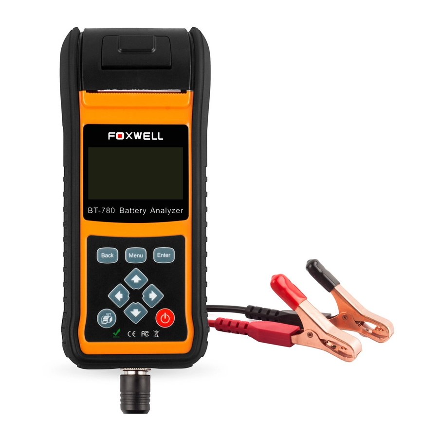
Tester Descriptions
This section illustrates external features, ports and connectors of the tester.

- LCD Display - shows menus, test results and operation tips.
- BACK Button - exits a screen and generally returns to previous screen.
- Menu Button - access the Main Menu options of the tester.
- ENTER Button - executes a selected option and generally goes to the next screen.
- /H UP and Down Buttons - selects an option or scroll to menu options.
- /G Left and Right Buttons - moves the cursor left or right to select characters when inputting the plate number of the car.
- Print Button - Prints test results through optional Bluetooth printer.
- Power Switch - Turn off/on battery for testing.
Do not use solvents such as alcohol to clean keypad or display. Use a mild nonabrasive detergent and a soft cotton cloth.
Accessory Descriptions
This section lists the accessories that go with the tester. If you find any of the following items missing from your package, contact your local dealer for assistance.
- BT-780 Battery Analyzer
- User's Guide
- O-1000A Current Clamp (Optional)
Specifications
Display: 128 * 64 pixels, large, backlit display screen
Working Temperature: -20 to 60°C (-4 to 140°F)
Storage Temperature: -20 to 70°C (-4 to 158°F)
Power Supply: 8-30V DC
Dimensions (L*W*H): 90*240*45mm
Net Weight (without printer): 0.8 KG
Net Weight (with printer): 1.0KG
Current Clamp
To test cranking amps and charging current, first connect the current clamp before tester startup, then turn on the current clamp power switch.
After tester connected, current clamp is able to work.
Press the reset key of the current clamp and connect the current clamp jaw to the anode wiring between the battery to be tested and the generator.
As the minimum width of the current clamp jaw is only 28mm, choose the connection cable or connection pole with diameter less than 28mm to test. Otherwise, the current clamp jaw cannot close completely.
NOTE:
- Current clamp jaw must close to avoid test tolerance.
- Current clamp uses 9V alkaline battery. Turn the clamp power off after using the current clamp.
- Before testing the current, take off the current clamp from the battery positive connection cable, and reset.
Operations
This section describes how to use the tester to perform tests on car batteries and 12V&24V starting and charging system. The menu-driven display will guide you step by step through the test process.
Connecting The Tester
The tester powers on automatically when it is correctly connected to the battery. The preferred test position is at the battery terminals. If the battery is not accessible, you may test at the jumper post; however, the power measurement may be lower than the actual value.
![]() To connect the tester:
To connect the tester:
- Clean the battery posts or side terminals.
- Connect the red clamp to the positive (+) terminal and the black clamp to the negative (-) terminal.
- Rock the clamps back and forth to make sure the clamps are firmly connected. In case the connection is poor, a "CHECK CONNECTION" message displays.
- When the tester is correctly connected, it boots up automatically and show the voltage of the battery

- Press the MENU button to go to the Main Menu.


NOTE
Do not connect the tester to a voltage source greater than 30V DC; otherwise you may damage the tester.
NOTE
If you are testing inside a vehicle, make sure all accessory loads are cut off, the key is not in the ON position and the doors are closed.
Battery Test
Battery Test is mainly targeted to analyze the battery healthy status to calculate the actual cold cranking capability of the battery and the aging extent, which provide reliable analysis evidence for the test and maintenance of the battery. It notifies the user to replace battery in advance when the battery is getting aged.
![]() To start a battery test:
To start a battery test:
- Scroll with the UP or DOWN button to highlight Battery Test from Main Menu and press the ENTER key.

- Scroll with the UP or DOWN button to highlight the voltage from Main Menu and press the ENTER key.

- Scroll with the UP or DOWN button to highlight the TEST TYPE from Main Menu and press the ENTER key.

- Scroll with the UP or DOWN button to highlight OUT OF VEHICLE or IN VEHICLE from BATTERY LOCATION menu and press ENTER to select the battery location.

- Scroll with the UP or DOWN button to highlight TOP POST or SIDE POST from POST TYPE menu and press ENTER to select the battery post type.

- Scroll with the UP or DOWN button to select the battery type from BATTERY TYPE menu and press ENTER to confirm.

- Scroll with the UP or DOWN button to select the battery standard from BATTERY STANDARD menu and press ENTER to confirm. Not all rating systems are available for each application.


You may find the battery type and battery rating label on every battery.
Global Rating Systems
| No. | Standard | Description | BT780 Testing Range |
| 1 | CCA | Cold Cranking Amps, as specified by SAE. The most common rating for cranking batteries at 0°F (-18°C) | 100-2000 |
| 2 | BCI | Battery Council International standard | 100-2000 |
| 3 | CA | Cranking Amps standard. The effective starting current value at 0°C (32°F). | 100-2000 |
| 4 | MCA | Marine Cranking Amps standard. The effective starting current value at 0°C (32°F). | 100-2000 |
| 5 | JIS | Japanese Industry Standard, shown on a battery as a combination of numbers and letters | 26A17--245H52 |
| 6 | DIN | Deutsche Industrie-Norm | 100-2000 |
| 7 | IEC | International Electrotechnical Commission | 100-2000 |
| 8 | EN | Europa-Norm | 100-2000 |
| 9 | SAE | Society of Automotive Engineers | 100-2000 |
| 10 | GB | China National Standard | 100-2000 |
- Use UP or DOWN button to change measure range till you enter the correct range of your battery. Press ENTER to start the test.

If your battery belongs to CCA system, just select the right CCA number and press ENTER to start the test.
- View test results on the screen. Depending on battery status, one of the following test results may display.


| No. | Test Results | Interpretation |
| 1 | GOOD BATTERY | The battery is in good condition. |
| 2 | GOOD-RECHARGE | The battery is in good condition but low current. Fully charge the battery and return it to service. |
| 3 | CHARGE & RETEST | Fully charge the battery and retest. Failure to fully charge the battery before testing may result in inaccurate results. If you still get CHARGE & RETEST message after you fully charge the battery, replace it. |
| 4 | REPLACE BATTERY | The battery is almost dead or the connection between the battery and battery cable is poor. Replace the battery and retest; or disconnect the battery cables and retest the battery using the out-of-vehicle test before replacing it. |
| 5 | BAD CELL-REPLACE | The battery may be damaged such as broken cell or short circuit. Replace the battery and retest. |
- Use UP or DOWN button to check the second page of battery test result which include state of health (SOH), state of charge (SOC), and resistance (RES).

- Press the BACK button to return to Main Menu. Or, press the ENTER button for cranking test if you are processing an in-vehicle test.

NOTE
The tester keeps the results of last test only. When you start a new test, the last results are overwritten.
Cranking Test
NOTE
Before starting the test, inspect the alternator drive belt. A belt that is glazed or worn, or lacks the proper tension, will prevent the engine from achieving the rpm levels needed for the test.
After an in-car battery test, the display alternates between the battery test results and the message PRESS FOR CRANKING TEST.
![]() To start cranking test:
To start cranking test:
- Press the ENTER button for cranking test.
- Start the engine when prompted.
- The tester displays the decision on the starter system, cranking voltage, and cranking time in seconds. For instance, as below display, the starter system is REPLACE BATTERT, cranking voltage is 10.76 V, and cranking time in second is 0.86 S.


| No. | Test Results | Interpretation |
| 1 | CRANKING NORMAL | The starter voltage is normal and the battery is fully charged. |
| 2 | LOW VOLTAGE | The starter voltage is low and the battery is fully charged. |
| 3 | CHARGE BATTERY | The starter voltage is low and the battery is discharged. Fully charge the battery and repeat the starter system test. |
| 4 | REPLACE BATTERY | Battery must be replaced before the starting system can be tested. |
| 5 | NO START | No vehicle start detected. |
| 6 | CRANKING SKIPPED | A start was not detected. |
- Press ENTER button to proceed with the charging system test, Print button to print the test results, BACK button to return to the main menu.
NOTE
For an in-vehicle test, the display alternates between the test results and the message. Press ENTER for charging test.
Charging System test
Once you have completed an in-vehicle test, the display alternates between the battery test results and the message press ENTER for charging test. Press ENTER to proceed with the charging test.
![]() To start charging system test:
To start charging system test:
- Follow the on-screen prompts to Rev the engine.
- Turn on high beams headlights and the blower fan.
- Rev engine with loads on.
- Idle engine and turn off loads.
- The Charging System decision is displayed at the end of the procedure.

| No. | Test Results | Interpretation |
| 1 | NO PROBLEMS | System is showing normal output from the alternator. |
| 2 | NO OUTPUT | No alternator output detected. Check all connections to and from the alternator, especially the connection to the battery. If the connection is loose or heavily corroded, clean or replace the cable and retest. If the belts and connections are in good working condition, replace the alternator. (Older vehicles use external voltage regulators, which may require only replacement of the voltage regulator.) |
| 3 | LOW OUTPUT | Alternator not providing sufficient to power the system's electrical loads and charge the battery. Check the belts to ensure the alternator is rotating with the engine running. Replace broken or slipping belts and retest. Check the connections from the alternator to the battery. If the connection is loose or heavily corroded, clean or reparable the cable and retest. |
| 4 | HIGH OUTPUT | Alternator voltage output exceeds the normal limits. Make sure there are no loose connections and the ground connection is normal. If there are no connection problems, replace the regulator. Most alternators have a built-in regulator that requires replacing the alternator. In older vehicles that use external voltage regulators, you may need to replace only the voltage regulator. |
| 5 | EXCESSIVE RIPPLE | Excessive AC ripple detected. One or more diodes in the alternator are not functioning or there is stator damage. |
- Use UP or DOWN button to check the RIPPLE.

- Press ENTER to print the test results or BACK to return to the main menu.

Viewing/Printing Test Results
View/Print menu lets you view test results and print the data via optional Bluetooth printer.
![]() To view and print the test results:
To view and print the test results:
- Scroll with the UP or DOWN button to highlight View/Print from Main Menu and press the ENTER key.

- Review the test results on the screen. Use the UP or DOWN button to scroll back and forth through Battery Result, Charging Result and Cranking Result to view.


- Press Lift button or Right button to check different test results.

- To print the test results, just press the Print button on the unit.

- Select Yes to type in the plate number so the test ticket could show test result with the exact plate number. Or select No to quit typing plate number.
- Follow the on-screen prompt to input the plate number.

- After entering the plate number, the test result will be printed.


NOTE
Build-in Battery is Alkaline Zinc-Manganese Dry Battery 9 volt. If the battery has no power please change it.
The results will be recorded even the battery has no power.
Language
Language menu lets choose system language. The test is set to English menu by default.
![]() To change the language setting:
To change the language setting:
- Scroll with the UP or DOWN button to highlight Language from Main Menu and press the ENTER key.

- Use the UP or DOWN button to select the language you need and press the ENTER key to confirm and return. Or press BACK button to return without saving.


Version Info
Version Info menu lets you view software information of the tester.
![]() To check the software version:
To check the software version:
- Select Version Info from the main menu. The follow screen shows the version of the tester.


Documents / ResourcesDownload manual
Here you can download full pdf version of manual, it may contain additional safety instructions, warranty information, FCC rules, etc.
Advertisement


Need help?
Do you have a question about the BT780 and is the answer not in the manual?
Questions and answers