Subscribe to Our Youtube Channel
Summary of Contents for unicore UFirebirdII-UC6580
- Page 1 INSTALLATION AND OPERATION USER MANUAL WWW.UNICORECOMM.COM UFirebirdII-UC6580 Evaluation Kit Copyright© 2009-2023, Unicore Communications, Inc. Data subject to change without notice.
- Page 2 UC6580 EVK User Manual Revision History Version Revision History Date R1.0 First release Apr.,2023...
- Page 3 Information, such as product specifications, descriptions, features and user guide in this manual, are subject to change by Unicore at any time without prior notice, which may not be completely consistent with such information of the specific product you purchase.
- Page 4 UC6580 EVK User Manual Foreword This document describes the use of the UC6580 evaluation kit (EVK) for the function and performance test of the chip. Target Readers This document applies to technicians who are familiar with GNSS receivers.
-
Page 5: Table Of Contents
Content Overview ....................1 EVK Introduction ..................2 Block Diagram ........................2 Power Supply ........................3 Configuration ........................3 Interface ....................4 USB Interface ........................5 Antenna Interface ......................5 Button ..........................5 Communication Mode Selection ..................5 Status Indicator ....................... 6 GNSS Power Supply Interface .................. -
Page 6: Overview
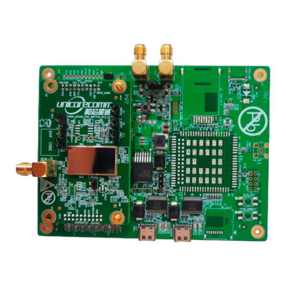
UC6580 EVK User Manual 1 Overview UC6580 evaluation kit (EVK) has two parts: bottom board and GNSS adapter. The bottom board connects to the GNSS adapter via the connector. The EVK is mainly used in the function and performance test of the chip UC6580 for the convenience of the users. -
Page 7: Evk Introduction
2 EVK Introduction Block Diagram FB2S-EVK Bottom Board USB1 USB To UART UART USB1-TypeC (FT232RL) 3.8V DC/DC (LM22679) 3.3V Backup (SGM2037) Battery V_BCKP UART1 UART2 GNSS_RST USB2 USB To UART UART2 RST Button USB2-TypeC (FT232RL) GNSS SPEED Connector IIC_Slave Test Point GPIO JTAG Figure 2-1 Block Diagram of Bottom Board... -
Page 8: Power Supply
UC6580 EVK User Manual Power Supply The EVK can be powered by a 5 V supply via the USB2.0 interface J17 or J6. You can directly connect it to the PC to communicate as well as supplying power. Configuration The bottom board provides many interfaces, such as two USB interfaces, a FWD signal SMA interface and a SPEED signal SMA interface. -
Page 9: Interface
3 Interface Figure 3-1 EVK FWD Signal SMA Interface (J12) SPEED Signal SMA Interface (J16) SPI/I C Mode Selection (J25) SPI/I C/PPS Test Point GNSS Antenna SMA Interface (J4) Status Indicator USB1 Interface (COM1,J17) USB2 Interface (COM2,J6) SPEED Signal Phase Selection (J20) (10) GNSS Reset Button (K4) (11) -
Page 10: Usb Interface
UC6580 EVK User Manual USB Interface The EVK supports two Type-C USB2.0 interfaces J17 and J6. See Figure 3-1 (7) and (8). USB1 and USB2 respectively correspond to UART1 and UATR2 of the GNSS adapter. Both of the two UARTs can be used to communicate with the host, but only UART1 can be used for firmware upgrade. -
Page 11: Status Indicator
Status Indicator Indicator Symbol Name Description UART1-RX Light on when receiving data; otherwise off UART1-TX Light on when sending data; otherwise off UART2-RX Light on when receiving data; otherwise off UART2-TX Light on when sending data; otherwise off Light on when there is power supply; Power indicator otherwise off Light on with low level voltage;... -
Page 12: Positioning And Power Consumption Test
UC6580 EVK User Manual 4 Positioning and Power Consumption Test Positioning Test Connect the GNSS antenna to the interface J4 on the adapter and fix the antenna in a non-occluded area . Connect the EVK to the PC through the USB interface. Then the power indicator is on. -
Page 13: Power Consumption Test
Power Consumption Test 4.2.1 Power Consumption in Running Mode To power the GNSS adapter, you can use an external voltage or the power from the bottom board. See 4.2.1.1 and 4.2.1.2 for the procedures to test the power consumption in the running mode with different power source. 4.2.1.1 Powered by Bottom Board When the adapter is powered by the bottom board. - Page 14 UC6580 EVK User Manual Figure 4-2 Testing Power Consumption If you just have one multimeter, you can measure the current VDDIO current DCDC_IN respectively. Make sure that when you measure either one of the current current values, the other jumper cap is installed. 4.2.1.2 Powered by External Voltage When you use the external voltage to power the adapter, the power consumption is...
-
Page 15: Power Consumption In V_Back Mode
Figure 4-3 Testing DCDC_IN current Compute the power consumption, which is equal to External Voltage × (VDDIO + DCDC_IN current current Similarly, if you do not have the one to two cable, you can measure the current VDDIO and DCDC_IN respectively. -
Page 16: Firmware Upgrade
UC6580 EVK User Manual 5 Firmware Upgrade Connect the EVK to PC through USB1 following the procedures described in section 4.1. Start the UPrecise. UPrecise User Manual Click Receiver Upgrade to do the upgrade. Refer to for more details. 6 Remark After connecting the PC, if a confliction between the serial port and the mouse happens, you can remove the serial enumerator in the advanced settings of the serial port property. - Page 17 和芯星通科技(北京)有限公司 Unicore Communications, Inc. 北京市海淀区丰贤东路 7 号北斗星通大厦三层 F3, No.7, Fengxian East Road, Haidian, Beijing, P.R.China, 100094 www.unicorecomm.com Phone: 86-10-69939800 Fax: 86-10-69939888 info@unicorecomm.com www.unicorecomm.com...


Need help?
Do you have a question about the UFirebirdII-UC6580 and is the answer not in the manual?
Questions and answers