Advertisement
- 1 GENERAL VIEW
- 2 SAFETY PRECAUTIONS
- 3 SUPPORTED READING DEVICE MODELS
- 4 OPENING THE DEVICE
- 5 MECHANICAL INSTALLATION
- 6 ELECTRICAL CONNECTIONS AND SETUP
- 7 POWER SUPPLY
- 8 SYSTEM WIRING
- 9 POWER SOURCE JUMPER SETTINGS
- 10 SHIELD TO PROTECTION EARTH JUMPER SETTINGS
- 11 CHASSIS GROUNDING JUMPER SETTINGS
- 12 9-PIN READING DEVICE AUXILIARY SERIAL INTERFACE
- 13 NETWORK BUS TERMINATION
- 14 BM100 BACKUP AND RESTORE MODULE (ACCESSORY)
- 15 INDICATOR LEDS
- 16 TECHNICAL FEATURES
- 17 Documents / Resources
The CBX100 is a connection box which can be used as an accessory to facilitate system connections for installation and device replacement of several Datalogic family reading devices.
System cabling is made through spring clamp terminal blocks inside the CBX100 while the reading device is connected to the CBX100 through a 25pin connector on the housing.
A 9-pin connector placed inside the CBX100 facilitates connection between an external PC and the auxiliary serial interface of the reading device for configuration or data monitoring.
CBX100 can also house an accessory Backup and Restore Module to make system maintenance extremely quick and easy.
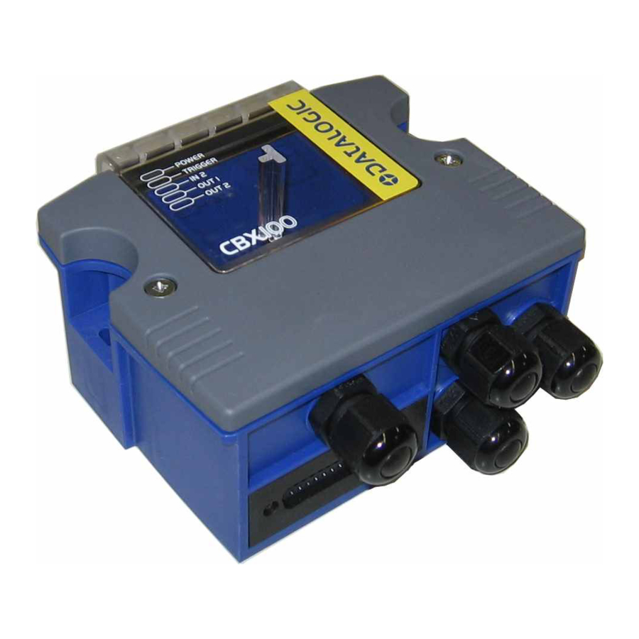
GENERAL VIEW

- Indicator LEDs
- Cover Screws (2)
- Compression Connectors (4)
- 25-pin Device Connector

- Power switch (ON/OFF)
- Auxiliary Port Connector
- Mounting Holes (2)
- ID-NET™Termination Resistance Switch
- Indicator LEDs
- Backup Module Connector
- Spring Clamp Terminal Blocks
- RS485 Termination Resistance Switch
- Power Source Selector
- Shield to Protection Earth Selector
- Chassis Grounding Selector
SAFETY PRECAUTIONS
ATTENTION: READ THIS INFORMATION BEFORE INSTALLING THE PRODUCT
POWER SUPPLY
This product is intended to be installed by Qualified Personnel only. This device is intended to be supplied by a UL Listed NEC Class 2 power source.

Total power consumption is given by adding the CBX100 power consumption to that of all the devices powered through the CBX100 (reading device, P.S., I/O). Refer to the manual of the connected devices for details about minimum/maximum supply voltage and power consumption.
Each CBX100 supports only 1 single reading device + system accessories.
SUPPORTED READING DEVICE MODELS
The CBX100 can be directly connected to the following readers through the 25-pin connector illustrated in Figure A.
| Linear Scanners | 2D Readers | ||||
| DS2100N | DS2400N | DS4800 | DS6300 | MATRIX-1000 | MATRIX-2000 |
| DS6400 | DX6400 | DS8100A | DX8200A | MATRIX 400 | |
 NOTE
NOTE
CBX100 is backward compatible with DS4600A, DS2100N/DS2400N (black body), and DS1100/DS2200 10-30 Vdc model reading devices using the ADP-MM1 25-pin gender changer. See the Gender Changer documentation for the relative CBX100 pinout.
OPENING THE DEVICE
To install the CBX100 or during normal maintenance, it is necessary to open it by unscrewing the two cover screws:
The CBX100 must be disconnected from the power supply during this operation.
MECHANICAL INSTALLATION
CBX100 can be mounted to various wooden or plastic surfaces using the two self-threading screws (3.9 x 45 mm) and washers provided in the package.
Mounting to other surfaces such as concrete walls or metallic panels requires user-supplied parts (screws, screw anchors, nuts, etc). A mounting template is included in the package to facilitate hole drilling alignment.
CBX100 can also be mounted to a DIN rail or a Bosch Frame using the following mounting accessories: BA100 (93ACC1821), BA200 (93ACC1822).
The diagram below gives the overall dimensions of the CBX100 and shows the two mounting through-holes.

Overall Dimensions
ELECTRICAL CONNECTIONS AND SETUP
The following figure shows a typical layout.

System Layout
The dotted line in the figure refers to an optional (temporary) hardware configuration in which a portable PC can be quickly connected to the CBX100 (and consequently to the reading device auxiliary interface) through the internal 9-pin connector. This allows monitoring of the data transmitted by the reading device or configuration through the utility program (see the reading device Installation Manual for more details). The reading device auxiliary interface signals are also available on the internal spring clamp connectors.
After making system cabling and switch settings, connect the reading device to the 25-pin connector on the CBX100 housing.
Switch ON the CBX100 power switch. The Power LED turns on (blue) when the power connection has the correct polarity. The Power LED turns on (red) in case of wrong polarity.
After system functioning has been verified, close the CBX100 using the 2 cover screws.
POWER SUPPLY
Power is supplied to the CBX100 through the Vdc and GND pins provided on the spring clamp connector.
The power switch switches the power supply ON or OFF for both the CBX100 and the connected reading device.

Power Switch ON/OFF Positions and Connections
The power switch does not control power to the Vdc/GND, +V/-V spring clamps, therefore any devices connected to these signals (i.e. external trigger, encoder, etc.), are live and are not protected from polarity inversion. Disconnect the power supply when working inside the CBX100.
NOTE
Vdc is electrically connected to +V, just as GND is electrically connected to -V. This is useful for supplying external trigger, inputs and outputs from the CBX100 power source, however +V and -V signals should not be used as power supply inputs to the CBX100.
The power supply must be between 10 and 30 Vdc only.
NOTE
To avoid electromagnetic interference:
- Connect CBX100 Protection Earth (Earth) to a good earth ground.
- Connect the reading device chassis to earth ground through the jumper, (default setting, see Figure 7).
- Connect the Network Cable Shield (Shield) to Filtered Earth through the jumper (default setting, see Figure 6).
SYSTEM WIRING
The connection and wiring procedure for CBX100 is described as follows:
- Open the CBX100 by unscrewing the 2 cover screws.
- Verify that the CBX100 power switch is off (see Figure 3).
- Unscrew the compression connectors and pass all the system cables through them into the CBX100 housing.
- To connect the power and input/output signals:
- Prepare the individual wires of the system cables by stripping the insulation back approximately 1 cm.
- Using a device such as a screwdriver, push down on the lever directly next to the clamp

- Insert the wire into the clamp and release the lever.

The wire will now be held in the spring clamp.
- Tighten the compression connector nuts so that the internal glands seal around the cables.
Flexible stranded wire should be used and must meet the following specifications.
All positions:
24 - 16 AWG
0.2 - 1.5 mm²
The CBX100 spring clamp connector pinouts are indicated in the Pinout table.
Refer to the reading device Installation Manual for signal details.

The input power signals Vdc, GND and Earth as well as the network signals REF, ID+, ID- and Shield are repeated to facilitate system cabling. In this way the power and network busses can enter and exit the CBX100 from different spring clamps but be physically connected together.
POWER SOURCE JUMPER SETTINGS
For most applications input power is provided through the dedicated spring clamp connectors inside the CBX100.
However CBX100 may accept power from the connected reading device through the 25-pin connector. This is useful, for example, to pass power to connected accessories such as Encoder and Presence Sensor from DX8200A VAC models or 6K/8K scanners powered directly through the network. See the relative reading device Reference Manual for details.
To power CBX100 from the reading device, the power source jumper must be placed in the "power from device" position as indicated in Figure below.

Power Source Jumper Settings
SHIELD TO PROTECTION EARTH JUMPER SETTINGS
The network cable shield (Shield) can be connected to Earth Ground (Earth) either directly or through a filter circuit. If the jumper is left open, the network cable shield (Shield) is floating.

Figure 6 - Shield to Protection Earth Jumper Settings
CHASSIS GROUNDING JUMPER SETTINGS
The reading device chassis grounding method can be selected by positioning a jumper. In this way the reading device chassis can be connected to earth ground (only if pin Earth is connected to a good earth ground). For all reading devices except 6K/8K, the chassis can alternatively be connected to the power supply ground signal (GND) or it can be left floating but, in this case, the jumper must be removed. For 6K or 8K scanners the chassis is internally connected to GND.

Figure 7 - Chassis Grounding
9-PIN READING DEVICE AUXILIARY SERIAL INTERFACE
The reading device auxiliary serial interface available on the internal CBX100 9-pin connector can be used either for configuration or for data monitoring.
Connections can be made to a PC or Laptop using a straight through cable or a USB-RS232 converter.
The details of the connector pins are indicated in the following table:
| CBX100 9-pin D-Sub Female Connector Pinout | |||
| Pin | Name | Function |  |
| 2 | TX | Auxiliary RS232 | |
| 3 | RX | Auxiliary RS232 | |
| 5 | SGND | Auxiliary Reference Ground | |
| 1, 4, 6, 7, 8, 9 | N.C. | ||
NETWORK BUS TERMINATION

ID-NET™ Termination Resistance Switch
The ID-NET™ termination resistance switch enables or disables the insertion of the bus termination resistor for ID-NET™ network applications.
In ID-NET™ network applications the termination resistor must be enabled ONLY on the first and last devices of the chain. On all the other devices this resistor MUST NOT be enabled (OFF).

RS485 HD Termination Resistance Switch
The RS485 HD termination resistance switch enables or disables the insertion of the bus termination resistor for RS485 Half Duplex Multidrop applications.
In Multiplexer applications the termination resistor must be enabled ONLY on the last device of the chain, the farthest away from the Multiplexer (assuming the Multiplexer is the first device of the chain). On all the other devices this resistor MUST NOT be enabled (OFF).
BM100 BACKUP AND RESTORE MODULE (ACCESSORY)
The BM100 Backup and Restore Module (separate accessory) provides configuration parameter backup. It can easily be installed by aligning it over its corresponding connector in the CBX100 and pushing down until correctly seated. When closed, the plastic support inside the CBX100 cover holds the module in place. For further details see the BM100 manual.

BM100 Accessory Mounting
INDICATOR LEDS

Indicator LEDs
There are five Indicator LEDs which signal power and I/O activity and are visible from the CBX100 outside cover.
The Power LED is blue when power is correctly applied to the CBX100 and the power switch is turned on.
This LED is red if power polarity is incorrect. In this case the connected reading device and optional Backup Module are protected.
If external I/O devices are powered through CBX100 (connected to +V/-V), they are not protected from polarity inversion.
The remaining four LEDs signal activity on the relative I/O lines. Their meaning depends on the software configuration of the connected reading device.
TECHNICAL FEATURES
| ELECTRICAL FEATURES | |
| Supply Voltage | 10 to 30 Vdc* |
| Consumption | 0.5 – 0.3 A |
| Limited Current Consumption CBX + reading device consumption (see related manual) | 2.5 A Max |
| USER INTERFACE | |
| LED Indicators | Power On/Polarity Error (blue/red) Trigger (yellow) IN2 (green) OUT1 (yellow) OUT2 (green) |
| PHYSICAL FEATURES | |
| Mechanical Dimensions | 138 x 128 x 62 mm (5.4 x 5 x 2.4 in.) |
| Weight | about 380 g. (13.40 oz.) |
| ENVIRONMENTAL FEATURES | |
| Operating Temperature | 0° to 50°C (+32° to 122°F) |
| Storage Temperature | -20° to 70°C (-4° to 158°F) |
| Humidity max. | 90% non condensing |
| Vibration Resistance EN 60068-2-6 2 hours on each axis | 14 mm @ 2 to 10 Hz 1.5 mm @ 13 to 55 Hz 2 g @ 70 to 200 Hz |
| Shock Resistance EN 60068-2-27 | 30 g; 11 ms; 3 shocks on each axis |
| Protection Class EN 60529 | IP65 (when compression connectors and reading device are correctly connected) |
The features given are typical at a 25°C ambient temperature (if not otherwise indicated).
* for further details about minimum/maximum supply voltage refer to the manual of the connected reading device, since the minimum supply voltage required may be >10.

Documents / ResourcesDownload manual
Here you can download full pdf version of manual, it may contain additional safety instructions, warranty information, FCC rules, etc.
Advertisement


Need help?
Do you have a question about the CBX100 and is the answer not in the manual?
Questions and answers