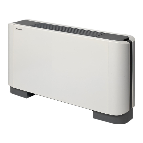
Summary of Contents for Daikin FXLQ20P7VEB
- Page 1 INSTALLATION AND OPERATION MANUAL System air conditioners FXLQ20P7VEB FXLQ25P7VEB FXLQ32P7VEB FXLQ40P7VEB FXLQ50P7VEB FXLQ63P7VEB FXNQ20P7VEB FXNQ25P7VEB FXNQ32P7VEB FXNQ40P7VEB FXNQ50P7VEB FXNQ63P7VEB...
- Page 2 Control box IN/D OUT/D Control box IN/D OUT/D Control box IN/D OUT/D Control box Control box IN/D OUT/D IN/D OUT/D NOTES...
- Page 3 4PW53090-2C...
-
Page 4: Table Of Contents
OTHER DAMAGE TO THE EQUIPMENT. BE SURE ONLY Places with mineral oil, or filled with oil vapour or spray like in TO USE ACCESSORIES MADE BY DAIKIN WHICH ARE kitchens. (Plastic parts may deteriorate.) SPECIFICALLY DESIGNED FOR USE WITH THE Where corrosive gas like sulphurous gas exists. -
Page 5: Important Information Regarding The Refrigerant Used
Accessories MPORTANT INFORMATION REGARDING THE REFRIGERANT USED Check if the following accessories are included with your unit. This product contains fluorinated greenhouse gases covered by the Kyoto Protocol. Refrigerant type: R410A value: 1975 GWP = global warming potential Metal clamp Insulation for liquid pipe Periodical inspections for refrigerant leaks may be required Drain hose... - Page 6 Install the unit according to the figures below. Unit of measurement = mm For FXLQ units only For FXNQ units only ≥100 ≥150 ≥100 ≥100 Model Front side 20+25 32+40 50+63 Air inlet direction Width of air inlet Air outlet direction Width of maintenance area 1030 1170...
-
Page 7: Indoor Unit Installation
Wallmounted installation NDOOR UNIT INSTALLATION As for the parts to be used for installation work, be sure to use the Check whether the wall is strong enough to bear the provided accessories and specified parts designated by our weight of the unit. If there is a risk, reinforce the wall company. -
Page 8: Refrigerant Piping Work
Use copper alloy seamless pipes (ISO 1337). The outdoor unit is charged with refrigerant. To prevent water leakage, execute heat insulation work completely on both sides of the gas and liquid piping. When using a heat pump, the temperature of the gas piping can reach up to approximately 120°C. -
Page 9: Drain Piping Work
Cautions for brazing RAIN PIPING WORK Be sure to carry out a nitrogen blow when brazing. Rig the drain pipe as shown below. Improperly rigged piping could Brazing without carrying out nitrogen replacement or releasing lead to leaks and eventually wet furniture and belongings. nitrogen into the piping will create large quantities of oxidized film on the inside of the pipes, adversely affecting valves and Carry out the drain piping... -
Page 10: Electric Wiring Work
Precautions LECTRIC WIRING WORK Observe the notes mentioned below when wiring to the power supply terminal board. General instructions Use a round crimp-style terminal for insulation sleeve for connection to the terminal block for wiring the units. When DANGER: ELECTRICAL SHOCK none are available, follow the instructions below. -
Page 11: How To Install The Remote Controller And Wiring Inside The Unit
Electrical characteristics Wiring installation Remove the control box cover and connect the wiring. Power supply Fan motor Voltage Model Volts range 0.015 0.015 0.025 50/60 220-240/220 ±10% 0.025 0.035 0.035 MCA: Minimum Circuit Amps (A) MFA: Maximum Fuse Amps (A) FLA: Full Load Amps (A) NOTE For details, refer to "Electrical data"... -
Page 12: Wiring Examples
IRING EXAMPLES IELD SETTING Field setting must be made on the remote controller in function of the Fit the power supply wiring of each unit with a switch and fuse as installation condition. shown in figure Setting can be made by changing the "Mode number", "First Power supply BS unit (only for heat code No."... -
Page 13: Test Operation
How to clean the air filter EST OPERATION Refer to the installation manual of the outdoor unit. Clean the air filter when the display shows " " (TIME TO CLEAN AIR FILTER). The operation lamp of the remote controller will flash when an error occurs. -
Page 14: Disposal Requirements
How to clean air outlet and outside panels Start up after a long stop Clean with soft cloth. Confirm the following: When it is difficult to remove stains, use water or neutral Check that the air inlet and outlet are not blocked. Remove any detergent. -
Page 15: Wiring Diagram
IRING DIAGRAM : TERMINAL BLOCK : BLACK : PINK : CONNECTOR : BLUE : RED : TERMINAL : BROWN : WHITE : FIELD WIRING : ORANGE : YELLOW : LIVE : NEUTRAL A1P....PRINTED CIRCUIT BOARD X1M....TERMINAL BLOCK (POWER SUPPLY) C1 .... - Page 16 4PW59127-1...


Need help?
Do you have a question about the FXLQ20P7VEB and is the answer not in the manual?
Questions and answers