Table of Contents
Advertisement
Quick Links
Advertisement
Table of Contents

Subscribe to Our Youtube Channel
Related Manuals for Pico Macom PFT-10


Summary of Contents for Pico Macom PFT-10
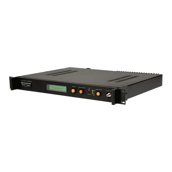
- Page 1 PICO MACOM Series 1310nm Optical Transmitter PFT Owners Manual Please read this manual thoroughly before use. Keep this manual handy for future reference. Visit Our Web-Site www.picomacom.com 858.546.5050 Contact Us Toll Free 800.421.6511...
-
Page 2: Safety Considerations
Pico Macom PFT 1310nm Optical Transmitter OWNERS MANUAL This manual is intended for use by purchasers of Pico Macom PFT Series Transmitter(s) and their qualified tech- nicians. This document is the property of Pico Macom and embodies proprietary subject matter. All design, manufacture, reproduction, use and sale rights regarding the same are expressly reserved. -
Page 3: Important Safeguards
PICO MACOM IMPORTANT SAFEGUARDS Pico Macom strongly advises you to read and understand the following safety instructions prior to installing and operating this equipment. • Read These Instructions first. All safety and operating instructions should be read before installing or operating this equipment. -
Page 4: Laser Safety Information
Fiber Optic PICO MACOM Series Laser Safety Information: The PFT-1310 Optical Transmitter modules are classified as Class 1M per IEC/EN 60825-1/A2:2001. This prod- uct complies with FDA/CDRH, 21 CFR 1040.10 and 1040.11 except for deviations pursuant to Laser Notice No. 50 dated 26 July, 2001. -
Page 5: Table Of Contents
PICO MACOM TABLE OF CONTENTS chapter 1 Introduction ...6 Introducing the Pico Macom PFT 1310nm Optical Transmitter ...6 Features ...7 chapter 2 specifications ...8 RF Performance ...8 Optical Performance ...8 General ...8 chapter 3 Installation and operation ...9 Unpacking the Unit ...9 Before Mounting ...9... -
Page 6: Chapter 1 Introduction
Macom offers optical passives for this purpose.) Contact your Pico Macom Sales Representative for further assistance if needed. Optical output connectors on the Pico Macom PFT are SC/APC type, common to the cable industry and used for their low loss and back reflection. Other connectors, most commonly, FC/APC type are used and may be available;... -
Page 7: Features
PICO MACOM The PFT offer both manual RF gain control (MGC) and automatic RF gain control (AGC) modes. Users are alerted to the mode which has been selected by two LEDs that indicate either AGC mode or MGC mode is active. For most RF signals, users may select AGC mode to control variations in the RF signal over time and maintain consis- tent modulation of the RF signal onto the optical carrier. -
Page 8: Chapter 2 Specifications
PICO MACOM 1. RF Performance sPecIfIcATIoN Frequency Range Connector Impedance Input Return Loss Input RF Level AGC Control Range MGC Control Range RF Frequency response (flatness) Carrier–to-Noise Ratio Composite Second Order (CSO) Composite Triple Beat (CTB) Front Panel Test Port Level * Results based on 110 channel Matrix carrier input, fiber link, and -1 dBm optical receiver input level. -
Page 9: Chapter 3 Installation And Operation
PICO MACOM Installation and Operation Unpacking the Unit Please inspect the cartons on receip and note damage to the carton and inspect for possible unit damage. If damage is found, please contact shipper immediately, before unpacking, to follow that shipper’s procedure for claims. -
Page 10: Making Rear Panel Connections
PICO MACOM Making Rear Panel Connections 4.1 Power Connection and Initial Power Up Insert the supplied power cord into the IEC320 male power socket on the chassis. Plug the opposite end of the cord into your local power source. The PFT includes an autoranging power supply for power source of 120 or 220 or 240 VAC, 50 or 60 cycles •... -
Page 11: Rf Input Connections
PICO MACOM Example of a fiber cable cleaner (source: Fiber Instrument Sales, www.fiberinstrumentsales.com). • Clean the jumper and connect to the Optical Power Meter. • Check that the front panel LASER LED is lighted green; if not, press the LASER ON/OFF button to turn the LED to green. -
Page 12: Using The Status Button
Adjusting Input Level for Reduced Number of RF Channels Laser transmitters are sensitive to both input (peak) level and the total power input Designs are targeted at typical loading of about 80 channels. There is sufficient “headroom’ is the design... -
Page 13: Connecting To Your Fiber Network
The PFT includes a DB-9 connector for future use by an EIA232 serial remote control protocol. The protocol is not available as of this writing. Contact your Pico Macom Sales Representative or the Pico Macom Field Service Manager (858-546-5050) to inquire further. -
Page 14: Decreased Output Due To Contamination
Exercise care that you do not bend or damage the internal fiber. 3. Clean bulkhead connector using Pico Macom fiber cleaning tools such as Optipop 2.5mm stick cleaner. Slide stick into the bulkhead and scrub contamination of the bulkhead. In the absence of commercial cleaning tools, a pipecleaner and isopropyl alcohol may be used. -
Page 15: Chapter 4 Input Level Versus Channel Loading
PICO MACOM Input Level versus Channel Loading The PFT Transmitters are designed to properly modulate the light output with a specified number of 6 MHz. channels. The PFT-x Specifications shows unit operation with 78 NTSC channels at 15 dBmV input level each, plus 300 MHz of QAM channels at –6 dB (9 dBmV) input level. If the number of higher level NTSC signals is reduced, the input levels may be increased to provide the same laser drive level and end-to-end performance. -
Page 16: Chapter 5 Output Power By Model
PICO MACOM • The table on the following pages is provided for reference. The table displays the PFT model number and the corresponding output power in dBm units and in mW (milliWatt) units. odel odel PfT-6 PfT -7 PfT -8... -
Page 17: Five-Year Limited Warranty
Price of the loaner unit plus shipping costs. When you receive the loaner unit, pack the failed unit in the loaner unit’s box and ship it freight prepaid to Pico Macom for repair. When you receive the re- paired unit, a new RMA number will be provided in the box. Carefully pack the loaner unit and affix the new RMA number on the box and ship it back to us for full credit excluding shipping costs. -
Page 18: Fiber Optic
List Price will apply beyond one week after the loaner or repaired unit are shipped to you. Other limitations may apply, so please call us for additional information on qualifying equipment and procedures. Pico Macom reserves the right to modify or discontinue the Uptime Loaner Program at any time, and at its sole discretion.
Need help?
Do you have a question about the PFT-10 and is the answer not in the manual?
Questions and answers