Advertisement
Quick Links
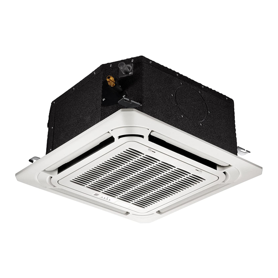
Disassembly Guide for CYB/CB Ceiling Cassette Air Handler (9K-18K BTU size)
Applies to Models with Nomenclature of "CB00xGMFILCFHD".
Disassembly
Compact
of
1.
Front Panel and Display Board
Procedure
1) Release 2 hooks and open the panel.
(see Figure 1.)
2) Remove two screws of wire line
(see Figure 2.)
Note: This section is for reference only. Actual unit appearance may vary.
Page 1
"CB01xGMFILCFHD".
Round Flow Cassette (9000, 12000, 18000 BTU sizes)
Illustration
Figure 1
Figure 2
Advertisement


Need help?
Do you have a question about the CYB Series and is the answer not in the manual?
Questions and answers