
Subscribe to Our Youtube Channel
Related Manuals for Esco Medical MIRI MRI-6A10-H-8


Summary of Contents for Esco Medical MIRI MRI-6A10-H-8
- Page 1 For research use only USER MANUAL MIRI Humidity Multiroom IVF ® incubators Rev. 3.0 Date of Revised 06.10.2021 Rx only...
- Page 2 Esco Medical Technologies, Ltd. Draugyste s street 19 • Kaunas, Lithuania Tel +370 37 470 000 medical.escoglobal.com • support-medical@escoglobal.com For Technical Service, contact North America Esco Technologies, Inc. 903 Sheehy Drive, Suite F, Horsham, PA 19044, USA Tel 215-441-9661 • Fax 484-698-7757 www.escolifesciences.us •...
- Page 3 (2) years from the original purchase date, pro- vided the instrument is calibrated and maintained following this manual. During the war- ranty period, Esco Medical will, at our option, either repair or replace a product that MIRI Humidity Multiroom IVF incubators User Manual Rev.
- Page 4 This warranty is limited to repairing the instrument per Esco Medical's specifications. When you return an instrument to Esco Medical for service, repair or calibration, we rec- ommend shipment using the original shipping foam and container. If the original packing materials are not available, we recommend the following guide for repackaging: •...
- Page 5 In an event where the seal must be broken to gain internal access to the instrument, you must first contact Esco Medical Ltd. You will be required to provide us with the serial number for your instrument, as well as a valid reason for breaking the Quality Seal.
-
Page 6: Table Of Contents
Table of contents 1 How to use this manual .......................... 10 2 Safety warning ............................10 3 Indication for use............................10 4 About the product ............................ 11 5 Transport, Storage and Disposal ......................12 5.1 Transportation requirements ..................... 12 5.2 Storage and operation environment requirements............13 5.2.1 Storage requirements ...................... - Page 7 13.2 User training ............................ 29 14 Alarms ................................ 30 14.1 Temperature alarms ........................30 14.2 Gas level alarms ..........................31 14.2.1 CO alarms ..........................31 14.2.2 O alarms ..........................31 14.3 Gas pressure alarms ........................32 14.3.1 CO pressure alarm ......................32 14.3.2 N pressure alarm .........................
- Page 8 27 Writing area on the compartment lids ..................47 28 Maintenance ............................47 29 Emergency Procedures........................48 30 User Troubleshooting .......................... 50 31 Specifications............................52 32 Electromagnetic compatibility ......................53 33 The Validation guide ..........................56 33.1 Product release criteria ......................56 33.1.1 Performance ..........................
- Page 9 36 Clinical use ..............................65 36.1 Temperature check ........................66 36.2 CO gas concentration check ..................... 66 36.3 O gas concentration check ....................... 66 36.4 CO gas pressure check ....................... 67 36.5 N gas pressure check ........................67 36.6 pH check ............................68 37 The Maintenance guide ........................
-
Page 10: How To Use This Manual
• If the equipment is used in a manner not specified by this manual, the protection provided by this equipment may be impaired. 3 Indication for use The Esco Medical MIRI family`s multiroom IVF incubators are intended to be used to pro-vide a ®... -
Page 11: About The Product
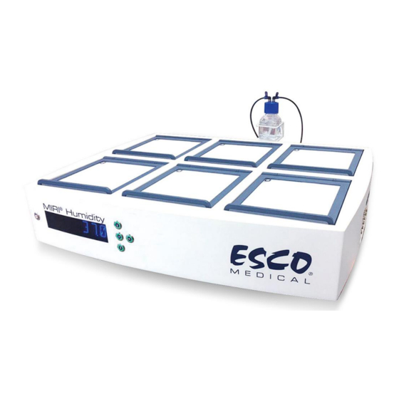
4 About the product The Esco Medical MIRI Humidity multiroom IVF incubators are CO gas incubators. ® Direct warming of the dishes in the chambers gives superior temperature conditions in compari- son to conventional multiroom IVF incubators. The temperature in the compartment will remain stable up to 1 °C (even when a lid is open for 30s) and will recover within 1 min after the lid is closed. -
Page 12: Transport, Storage And Disposal
A pH sensor port is part of the DAQ package. The user can plug any standard BNC pH probe to the unit and measure the pH in the samples at will. The MIRI Humidity multiroom IVF incubator can be connected to a PC running the Esco Medical ® Data logger software for long term data logging and data storage. -
Page 13: Storage And Operation Environment Requirements
A visual inspection should be done if there is any damage. If no damage is found, the MIRI ® midity multiroom IVF incubator can be prepared for transport. These labels should be glued on the box: • Label with the marked packing date •... -
Page 14: Supplied Service Parts And Accessories
• 6 warming blocks • 4 warranty labels • 1 pump box calibration tool • 1 USB stick containing Esco Medical Data logger software and a PDF version of the user manual • 1 medical grade power cord • 1 3.5 mm external alarm jack connector •... - Page 15 Table 7.2 Device and “For research use only” labels Description Image 1. Model. 2. Mains power rating. 3. CE mark. 4. Not protected against the ingress of water. 5. Manufacturer’s address and country of origin. 6. View instruction for use. 7.
-
Page 16: Important Safety Instructions And Warnings
® 8 Important safety instructions and warnings 8.1 Before installation 1. Do not use the product if the package is damaged. Contact Esco Medical or the local repre- sentative. 2. Read the user manual thoroughly before use. 3. Always keep these instructions easily accessible near the device. -
Page 17: Post Installation
N gas supply pressures are kept stable at 0.4 – 0.6 bar (5.80 – 8.70 PSI). 10. Never use any other except Esco Medical filter. Otherwise, the warranty will be void. 9 Getting started MIRI Humidity incubators must be installed by authorized and trained personnel ®... -
Page 18: Mains Connection
10 Mains connection The MIRI Humidity multiroom IVF incubators come with a detachable mains power cord. The ® power cord is prepared for the country in which the unit is intended to be used. The ON/OFF switch provides the user with a means to isolate the MIRI Humidity multiroom IVF ®... -
Page 19: User Interface
The inlet's gas pressure should be between 0.4 – 0.6 bar (5.80 – 8.70 PSI) and it must be kept stable! Always use a high-quality pressure regulator that can be set with the required precision for both gases. Figure 11.2 Pressure regulator Connect the CO gas to the CO inlet with a suitable silicone tube. -
Page 20: Activating The Heat And Gas Controls
Table 12.1 The main keys and their purpose Description Image Main keys ON/OFF button Located in the REAR of the unit Alarm key It mutes an audible alarm and visually indicates the alarm condition by a flashing red circle of light. The audio alarm will come back on after 5 min. -
Page 21: System Menu
12.2 System menu Press and hold (⇧) and (⇩) keys together for 3 seconds to access the menu. Navigate in menu using: • Arrow right (⇨) key = enter • Up (⇧) and Down (⇩) arrow keys= previous OR next •... -
Page 22: Temperature Sub-Menu
You can exit the menu by pressing the (⇧) key. Temperature is the first category when you enter the menu. Press the (⇨) key to enter the Temperature sub-menu. Press the (⇩) key to scroll further down in the menu. Press the (⇨) key to enter the CO sub-menu. -
Page 23: Co Sub-Menu
Example – how to calibrate the temperature: The temperature has to be measured with a suitable and calibrated device. With a quality ther- mometer, it has been estimated that T1 is 37.4 °C. Locate “T1 CAL” in the sub-menu and press and hold the SP key. - Page 24 Move to the next CO sub-menu item with (⇩) key or one step up with (⇧) key. flow rate is shown (it cannot be adjusted): It shows the amount of CO gas put into the system while regulating. The volume is shown in li- ters/hour.
-
Page 25: O 2 Sub-Menu
Calibration values should only be changed by a trained user or the technician, according to specific measurements. Measurements should only be performed with a calibrated device. 12.4.3 O sub-menu Press the (⇨) key on O to enter the O sub-menu. The first item in the O sub-menu is O sensor calibration:... -
Page 26: Service Sub-Menu
The value is in bar and it must be 0.4 – 0.6 bar (5.80 – 8.70 PSI) at all times. Example – how to calibrate the O gas concentration has to be measured with a suitable and calibrated device. The actual O con- centration has been estimated to be 5.3% on one of the gas sample ports. -
Page 27: Installation With Premixed Gas
Ver 2.0 is only shown as an example. Consult Esco Medical or the local representative for the num- ber of the latest version. Move to the next service sub-menu item with (⇩) key or one step up with (⇧) key. - Page 28 Instead of connecting MIRI Humidity multiroom IVF incubators to either only 100% CO or both ® 100% CO and 100% N , the incubator is attached to only a premixed source. Premixed gas should only be connected to the CO gas port (a 4 mm diameter hose barb).
-
Page 29: User Training
The display will show the “GAS” function: Press the (⇨) key to enter and press (⇩) or (⇧) keys to choose “PREMIX” or “CO ”. Press the SP key and by pressing (⇩) or (⇧) keys, select “PREMIX” or “CO ”... -
Page 30: Alarms
4. If they change to another concentration, the MIRI Humidity multiroom IVF incubators set- ® points must be adjusted accordingly, as described above. They should also check the flow rates when they change to a new bottle if it does not precisely contain the same gas mixture. 14 Alarms The display will show a red “A”... -
Page 31: Gas Level Alarms
The zone layout and sensor placement are described in the section “16 Surface temperatures and measuring temperature”. If a temperature sensor malfunctions, it will be indicated by the following warning: It denotes that the sensor in compartment 2 has failed. As a safety precaution, the heating of the affected area will be switched off. -
Page 32: Gas Pressure Alarms
Remember that changing the setpoint more than ±1% from the current gas level will result in a gas level alarm. The same goes for all calibration adjustments. % is too low: % is too high: The display will lock on the alarm condition and will stop alternating between the standard status messages. -
Page 33: Multiple Alarms
“P” stands for pressure. The display will lock on the alarm condition and will stop alternating between the standard status messages. If the mute key is pressed, the display will shift to normal status and show the parame- ters for 5 minutes until the audio alarm comes back on again. The mute alarm key will still show the alarm condition by blinking red while the alarm is muted. -
Page 34: The Co Gas Concentration Setpoint
2. Hold down the SP key and use (⇧) and (⇩) keys to adjust the setpoint: one keypress corre- sponds to a 0.1 change. 3. After changing the temperature, let go of the SP key. The value is now stored. If the display does not show the current temperature reading, the (⇨) key will toggle between the temperature, CO and mode readings. -
Page 35: The Culture Mode
2. Hold down the SP key and use (⇧) and (⇩) keys to adjust the setpoint: one keypress corre- sponds to a 0.1 change. 3. After changing the temperature, let go of the SP key. The value is now stored. If the display does not show the current O reading, the (⇨) key will toggle between the tempera- ture, CO... -
Page 36: Surface Temperatures And Measuring Temperature
(in 4 well dishes). If the media stays longer without oil coverage, a high risk of media osmolal- ity changes appears. If you have any questions or uncertainty, consult Esco Medical or your local representative before using open culture mode in the MIRI Humidity incubator. -
Page 37: Pressure
Temperature calibration is done by adjusting the Tx (where x is the sensor number) according to a measurement done on the spot relevant to the dish placement. After temperature adjustment, give it at least 15 minutes for the temperature to sta- bilize, use the thermometer to verify the correct temperature on each area. -
Page 38: Gas Pressure
The CO pressure is shown in bar. External pressure must be between 0.4 – 0.6 bar (5.80 – 8.70 PSI) at all times. It cannot be adjusted on the MIRI Humidity multiroom IVF incubator; it must be ® done on the external gas regulator. Remember there is a pressure alarm on the pressure limits: if the pressure falls below 0.3 bar or rises above 0.7 bar (4.40–... -
Page 39: Ph Measuring
Ver 2.0 is only shown as an example. The current MIRI Humidity multiroom IVF incubator firm- ® ware version is 7.0A. 2. Press the (⇧) key to exit back into the sub-menu. 19 pH measuring Validating the pH of the culture media should be a standard procedure. The MIRI Humidity multiroom IVF incubators are equipped with a high-grade pH measuring sys- ®... - Page 40 Figure 19.2 pH view in the Datalogger The recommended method to use the system is to fill a 4-well dish with 3 types of buffers in 3 of the wells (one type in each) and fill the 4 well with the culture media. Place the 4-well dish in one empty compartment and leave it to equilibrate.
-
Page 41: Safe Sense Function
Figure 19.4 4-well dish with 3 buffers and media Set the buffer levels with the (+) and (-) keys to correspond to the buffers used. Before measuring in the culture media, calibrate the probe in 2 or 3 buffers. It is necessary to rinse the probe between each insertion. -
Page 42: Cleaning Instructions
21 Cleaning instructions 21.1 Considerations about a sterile device The MIRI Humidity multiroom IVF incubators are not sterile devices. They are not delivered ster- ® ile state and it is not possible to keep them sterile when in use. However, their design was created with great care to make it easy for the user to keep the device sufficiently clean during use and not contaminate the key components. -
Page 43: Manufacturer Recommended Disinfection Procedure
21.3 Manufacturer recommended disinfection procedure Disinfection of the device (with no embryos inside) The use of gloves and good handling techniques are essential for successful disinfection. Proceed with the following steps (this procedure has been demonstrated during the on-site train- ing program as part of the installation protocol): 1. -
Page 44: Humidification
Please consult Esco Medical or your local representative before using “Open culture” mode in the MIRI Humidity incubator if you have any questions. -
Page 45: Gas Level Validation
The compartment’s temperature conditions can be continuously logged through the external con- nectors on the unit's side without compromising its performance. Any logging system that uses standard PT-1000 sensors may be used. Esco Medical can supply an external logging system (MIRI – GA12) for the sensors. ®... -
Page 46: Alarm Switch For An External System
Taking out a large sample volume may affect gas regulation. Make sure that the gas analyzer is calibrated before use. 26 Alarm switch for an external system The MIRI Humidity multiroom IVF incubator can be connected to an external monitoring system, ®... -
Page 47: Writing Area On The Compartment Lids
Figure 26.2 “Open circuit” alarm mode Whenever the MIRI Humidity multiroom IVF incubator's power cord is disconnected ® from the power source, this switch will automatically indicate an alarm! It is an extra safety feature intended to alert the personnel in case of a power cut in the laboratory. 27 Writing area on the compartment lids Each compartment lid on the MIRI... -
Page 48: Emergency Procedures
2. In-line HEPA filters must be replaced yearly during annual maintenance. 3. According to the clinical practice intervals, suitable cleaning is in the laboratory where the MIRI Humidity multiroom IVF incubators are used. The manufacturer does not recom- ® mend periods longer than 14 days between cleaning. It is essential to perform the inspection and service at the intervals indicated in the MAINTENANCE section below. - Page 49 There will be a 30-minute-long interval during which the user can assess if the condition is tem- porary or permanent. If the state is permanent, remove all the samples and place them in an alter- native or backup device that is not affected by the problem. If the condition is temporary and the level is low, keep the lids shut.
-
Page 50: User Troubleshooting
30 User Troubleshooting Table 30.1 Heating system Symptom Cause Action The unit is switched off at the back or Switch the device on or connect No heating, the display is off not connected to the power the power The temperature is more than 0.5 °C off the set temperature The setpoint for temperature is No heating... - Page 51 Please refer to the software instal- not correctly installed lation guide Table 30.5 Display Symptom Cause Action Contact your Esco Medical Dis- Missing segment(s) in display Failure in the PCB tributor to replace the PCB Table 30.6 Keyboard Symptom Cause...
-
Page 52: Specifications
31 Specifications Table 31.1 MIRI Humidity incubator specifications ® Technical specifications MIRI Humidity ® Overall dimensions (WxDxH) 700 x 645 x 280 mm Weight 40 kg Material Mild steel / Aluminum / PET / Stainless steel Power supply 115V 60Hz OR 230V 50Hz Power consumption 300 W Temperature control range... -
Page 53: Electromagnetic Compatibility
32 Electromagnetic compatibility Table 32.1 Electromagnetic emissions Guidance and manufacturer’s declaration – electromagnetic emissions The MIRI Humidity multiroom IVF incubators are intended for use in the electromagnetic environment specified ® below. The customer or the user of the MIRI Humidity multiroom IVF incubator should ensure that it is used in such ®... - Page 54 Guidance and manufacturer’s declaration – electromagnetic immunity The MIRI Humidity multiroom IVF incubators are intended for use in the electromagnetic environment specified ® below. The customer or the user of the MIRI Humidity multiroom IVF incubator should ensure that it is used in such ®...
- Page 55 Table 32.3 Recommended separation distances Recommended separation distances between portable and mobile RF communication equipment and MIRI Humidity multiroom IVF incubators ® The MIRI Humidity multiroom IVF incubators are intended to be used in an electromagnetic environment in ® which radiated RF disturbances are controlled. The customer, or the MIRI Humidity multiroom IVF incubator ®...
-
Page 56: The Validation Guide
33 The Validation guide 33.1 Product release criteria The Esco Medical MIRI Humidity multiroom IVF incubators undergoes strict quality and perfor- ® mance testing before being released for sale. 33.1.1 Performance Each component used in the MIRI Humidity multiroom IVF incubator is tested during the manu- ®... -
Page 57: Cosmetic
34 Validation on-site Even though at Esco Medical, we strive to do the most comprehensive tests before the device is shipped to the customer, there is no way to be sure that everything is still OK at the location when the device is set up. -
Page 58: Recommended Additional Equipment
34.2 Recommended additional equipment All equipment must be of high quality and calibrated. • A VOC meter able to measure the most common volatile organic compounds at least at the ppm level. • With the laser particle counter, a sample should be taken just above the MIRI Humidity ®... -
Page 59: Gas Supply N
Bulk liquid carbon dioxide is commonly maintained as a refrigerated liquid and vapor at pressures between 1,230 kPa (approx. 12 bar) and 2,557 kPa (approx. 25 bar). Carbon dioxide may also exist as a white opaque solid with a temperature of -78.5 °C under atmospheric pressure. A high concentration of carbon dioxide (10.0% or more) can asphyxiate quickly with- out warning with no possibility of self–rescue regardless of the oxygen concentration. -
Page 60: About N
The use of N gas with moisture will damage the flow sensors. Moisture level must be verified on the gas manufacturer's certificate: only 0.0 ppm v/v Max is permissible. 35.2.1 About N Nitrogen makes up a significant portion of the earth's atmosphere with 78.08% by volume. Nitro- gen is a colorless, odorless, tasteless, non-toxic, and almost inert gas. -
Page 61: Voltage Supply
For safety, this unit has a built-in digital gas pressure sensor that monitors the incoming gas pres- sure and alerts the User if any drop is detected. Remove the inlet gas line for the N gas. Attach the gas line to the gas pressure measuring device. PASS: The value must be 0.4 –... -
Page 62: Gas Concentration Check
35.7 O gas concentration check The O gas concentration is checked for deviation. The gas sample port on the side of the unit is used. Use sample port-6 for validation. Remember not to open any lid at least 10 min before starting the test nor during the testing itself. -
Page 63: Temperature Check: Compartment Lids
close the lid and wait until the temperature has stabilized. Be careful when closing the lid so as not to dislocate the sensor placement in the droplet. Place the thermometer sensor on each zone and verify the temperature. If calibration is needed, please refer to the "12.4.1 Temperature sub-menu" section for more in- formation on how to perform the temperature calibration. -
Page 64: Cleaning
If the N is not available, the test can be done without it. Make sure that the Esco Medical data logger software is running. Check that parameters are logged and give a meaningful reading. Let the device run without inter- fering for at least 6 hours. -
Page 65: Test Documentation Form
35.12 Test documentation form The "Installation report" form must be completed with the tests-passed status filled by installation personnel and submitted to Esco Medical before the device is taken into clinical use. 35.13 Recommended additional testing 35.13.1 A laser particle counter... -
Page 66: Temperature Check
36.1 Temperature check The temperature check is performed using a high-precision thermometer. Place the thermometer on each zone and verify the temperature. Calibrate if necessary. Please refer to the "12.4.1 Temperature sub-menu" section for more information on how to per- form the temperature calibration. -
Page 67: Co Gas Pressure Check
Humidity multiroom IVF incubators will ® not be affected, as the gas in the compartment is not under pressure, and the reading is just an artifact based on unsuitable measuring equipment. Contact Esco Medical or the local distributor for further guidance. 36.4 CO... -
Page 68: Ph Check
Please refer to the "19 pH measuring" section for more information on performing pH calibration. 37 The Maintenance guide Your MIRI Humidity multiroom IVF incubator from Esco Medical contains high precision quality ® components. These components are chosen to ensure the high durability and performance of the equipment. -
Page 69: Humidification Bottle
CO regulator system. Please follow these safety precautions when changing the filter: • Always use the original filter (contact Esco Medical or your local distributor for more de- tails or ordering). • Change the filter once every year. -
Page 70: In-Line Hepa Filter For N
N regulator system. Please follow these safety precautions when changing the filter: • Always use the original filter (contact Esco Medical or your local distributor for more de- tails or ordering). • Change the filter once every year. -
Page 71: Co Sensor
This sensor's lifetime is more than 6 years, but for safety reasons, Esco Medical recommends the sensor to be replaced once every 4-years. Please follow these safety precautions when changing the sensor: •... -
Page 72: Proportional Valves
Please follow these safety precautions when changing the internal gas pump: • Always use an original gas pump (contact Esco Medical or your local distributor for more details or ordering). • Change the gas pump within 2 years from the date of installation. -
Page 73: Flow Sensors
The flow sensors are used by the CO regulations and for logging the unit's gas consumption. This sensor's lifetime is more than 3 years, but Esco Medical recommends the sensor to be re- placed once every 2 years for safety reasons. -
Page 74: Internal 0.2Μ Filter For N Gas
Please refer to the service manual for replacement instructions. 37.14 Firmware update If Esco Medical has released a newer version of the firmware, this should be installed on the MIRI ® Humidity multiroom IVF incubators during the yearly scheduled service. -
Page 75: Before Installation
All individuals who will perform installation, repair and/or maintenance of the instrument must be trained by Esco Medical or at a qualified training center. Experienced service technicians or embryologists conduct training to ensure that the installation personnel clearly understand the instrument's functions, performance, testing, and maintenance. -
Page 76: Bring The Following To The Installation Site
38.4 Bring the following to the installation site • "Installation report" form. • Service manual for the MIRI Humidity multiroom IVF incubators. ® • Updated service tool kit. • Memory stick with the latest released firmware & software. • High precision thermometer with a resolution not less than 0.1 °C. •... -
Page 77: After The Installation
When the installation trip is finished, a copy of the original "Installation report" form must be sent to Esco Medical Ltd. It will be saved with the device records. According to the ISO procedure and Medical Device Directive, a paper copy of the completed and signed installation test form is stored in the unique device's device history record.
Need help?
Do you have a question about the MIRI MRI-6A10-H-8 and is the answer not in the manual?
Questions and answers