
Related Manuals for Perfect Comfort PCKK Series


Summary of Contents for Perfect Comfort PCKK Series
- Page 1 PCKK SERIES PACKAGED TERMINAL AIR CONDITIONER/HEAT PUMP WITH UNIVERSAL HEATER Installation, Operation and Maintenance Manual MODELS: PCKK09K235HTM3, PCKK12K235HTM3 Page | 1...
-
Page 2: Table Of Contents
Table of Contents 1. Read This First ……………………………………………………………………..……………………………………….…….3 To the installer………………………………………………………………………………..……………………………..…….3 General precautions …………………………………………………………………..…………...…………………….…… 3-4 2. Check List …………………………………………………….………………………………………….…………………….…… 4-6 3. General Product Information ………………………………………..……………………………………………...…… 7 Product description …………………………………………………..…………………………………………………..…….7 Standard controls and components ………………………………………………..…………..……………………… 7 Operation Instructions ..……………………….………………………………………………………..…………………… 8 Manual Control to Thermostat Instructions………………………………….……………..……………..………. 9 Model coding ………………………………………………………………………………...………..…………………………... -
Page 3: Read This First
GROUNDING: Unit MUST be grounded from branch circuit through service cord to unit, or through separate ground wire provided on permanently connected units. Be sure that branch circuit or general purpose outlet is grounded. Do not modify the PERFECT COMFORT PTAC POWER CORD Page | 3... -
Page 4: Check List
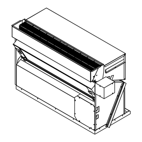
The power cord should be checked before every use. Do not use the product if the cord has failed the test. A damaged power cord must be replaced with a new cord from the manufacturer and not repaired. The use of extension cords is prohibited. RECEPTACLE: The field supplied outlet must match plug on service cord and be within reach of service cord. - Page 5 Fig.01: Typical Configuration 1. Front Cabinet The tabs on the cover and inserts on the sleeve should be checked for correct Fig.02 Filter placement and fitting. 2. Cooing Chassis and Fan Section The unit nameplate should be checked to make sure the voltage agrees with the power supply available.
- Page 6 Thermostat Wiring Harness and Installation, Manual located in plastic bag. Operation and Maintenance Manual For this replacement PTAC only 2 (Cooling Chassis and Fan Section) & 6 (Filter) are provided. Page | 6...
-
Page 7: General Product Information
General Product Information Product Description Perfect Comfort replacement package terminal air conditioners have a cooling chassis with electric heat. The PERFECT COMFORT PTAC unit 1. Use R410A refrigerant. This refrigerant is not affected by a phase out schedule. R410 is environment friendly. -
Page 8: Operation Instructions
Operation instructions Controls ON/OFF button: When unit is off; press this key to turn the machine on. When the ON/OFF machine is on, press this key to turn off the unit. Use the mode button to select heat/cooling or fan options. MODE button: Mode selecting key, press the key, mode change as follows. -
Page 9: Manual Control To Thermostat Instructions
How to Change from Manual control to Thermostat for PCKK Please follow the instructions and pictures Step 1. Take the unit out of its sleeve Step 2. Remove the front grill to access the display panel (DO NOT drop anything in fan unit ) Step 3. -
Page 10: Model Coding
Page | 10... -
Page 11: Preparing For The Installation
Each unit must have a separate branch circuit protected by a fuse or breaker. Refer to the unit rating plate for the proper wire and breaker or fuse size Use of extension cords is prohibited DO NOT connect the PERFECT COMFORT unit to a circuit with an incorrectly-sized overcurrent- protection device Electrical short hazard Before opening the existing unit: Open the power supply disconnect switch. -
Page 12: Removing Old Chassis
3. Loosen any tie- down bolts or screws and remove the old chassis Check existing wall sleeve PERFECT COMFORT replacement PTAC’s are to be used with a metal wall sleeve: a) Clean the wall sleeve of any dirt b) Repair any damage or rust c) Ensure proper drainage of condensate or rainwater to exterior of building d) Check the back of sleeve is pitched to the outside ¼... -
Page 13: Wall Thermostat Installation
WALL THERMOSTAT INSTALLATION Connect the wall thermostat cable with the chassis. See Fig.03 for wire colour coding. Install the wall thermostat as per instructions from thermostat manufacturer. Connect cable from chassis to the existing wires in the wall as Fig.04 Ensure to wrap and make protection at the joint points. -
Page 14: Filter Installation
FILTER INSTALLTION Filter is installed inside cover near the bottom. It rests on the metal that protrudes around the bottom of the over. See Fig. 06. Make note to have the angled corner near the power cord. This small section is for the power cord to exit the unit. -
Page 15: Final Inspection And Start Up
FINAL INSPECTION AND START-UP Check list 1. Ensure the chassis is secured with the sleeve 2. Unit is installed in compliance with all codes 3. Circuit breakers and wire sizes are correct 4. Ensure the electrical supply matches the electrical requirements of the unit, and that the unit is properly grounded 5. -
Page 16: Maintenance And Troubleshooting
Maintenance and Troubleshooting Monthly inspection and maintenance DANGER Electrical shock hazard. Disconnect power to the PERFECT COMFORT replacement PTAC before servicing or accessing the control compartment. Failure to do so could result in severe personal injury or death. WARNING It is illegal to discharge refrigerant into the atmosphere. Use proper reclaiming methods and equipment when servicing a perfect comfort replacement PTAC. -
Page 17: Seasonal Start-Up And Maintenance
NOTICE If a new air filter is needed for your PERFECT COMFORT replacement PTAC, consult supplier for availability and/or proper sizing. SEASONAL START-UP AND MAINTENANCE At the beginning of the cooling and heating seasons, a complete mechanical check should be performed and maintenance/inspections performed as described below. -
Page 18: Troubleshooting
TROUBLE SHOOTING GUIDE SYMPTOM CAUSE CHECK/CORRECTION Sleeve seals are worn or missing allowing outdoor air to be passed Inspect and replace if necessary over the thermostat sensing bulb Thermostat does not properly Defective thermostat Test and replace if necessary control room temperature, runs Ensure bulb is clipped to evaporator continuously or... - Page 19 SYMPTOM CAUSE CHECK/CORRECTION Indoor coil frozen See “Evaporator Coil Frosts” Ensure that curtains or other obstructions are not short circuiting air Compressor Short Recycling of indoor air between the outlet grille and return air Cycles (Cont.) intake Compressor may be mis-wired. Check Compressor running too slow and capacitator.
- Page 20 SYMPTOM CAUSE CHECK/CORRECTION Disconnect overload from compressor terminals. Check for winding resistance across all winding pairs. C-S, C-R, S-R and check each terminal to the Compressor windings open compressor shell for ground faults. Replace compressor if any windings are Compressor will open-circuited or short circuited to the not run (Cont.) shell...
- Page 21 SYMPTOM CAUSE CHECK/CORRECTION Dirty air filter Clean or replace Dirty evaporator coil Clean as necessary Check to see if blower wheel or shaft is being rubbed or experiencing external friction. Check free rotation of the Blower motor operating motor shaft. Check voltage to the intermittently, rotating slowly, or motor.
- Page 22 SYMPTOM CAUSE CHECK/CORRECTION Defective compressor Check and replace if necessary Refrigerant line hitting surroundings Bend tube slightly to obtain clearance Unit Rattles or is Noisy Loose fan, blower, or motor mounts Check and tighten if necessary Rubbing of fan or blower on Ascertain cause and correct.
- Page 23 SYMPTOM CAUSE CHECK/CORRECTION Faulty thermostat Test and replace if necessary Automatic reset high limit control Replace high limit calibration defective Dirty air filter Clean or replace Dirty evaporator coil Clean as necessary Heater Output Intermittent or Check to see if blower wheel or shaft is Insufficient being rubbed or experiencing external friction.
-
Page 24: Error Code
Error Codes Error code Error Presentation Indoor temperature sensor broken/short circuit Temperature sensor of indoor condenser coil broken/short circuit Outdoor environment temperature sensor broken/short circuit Protection of lack cooling liquid Pressure switch protection Position of DIP switch error Low temperature and low pressure protection of outdoor cold water Page | 24...