
Related Manuals for Daikin EKHBX008BA Series


Summary of Contents for Daikin EKHBX008BA Series
- Page 1 INSTALLATION MANUAL Indoor unit for air to water heat pump system EKHBH008BA EKHBX008BA...
- Page 2 ≥350 1-1/2" MBSP 1" MBSP...
-
Page 3: Table Of Contents
12. The units can be Field settings.................... 23 Field settings table ................... 32 combined with Daikin fan coil units, floor heating applications, low temperature radiators, Daikin domestic water heating applications Test run and final check..............34 and Daikin solar kit for domestic hot water applications. -
Page 4: Scope Of This Manual
Connection to a benefit kWh rate power supply NOTE An ERLQ0* BA outdoor unit can only be This equipment allows for connection to benefit kWh rate power connected to an EKHBH/X008 BA indoor unit supply delivery systems. Full control of the unit will remain possible (bottom plate heater at outdoor unit has to be only in case the benefit kWh rate power supply is of the type that controlled by indoor unit). -
Page 5: Safety Considerations
Caution AFETY CONSIDERATIONS Earth the unit. The precautions listed here are divided into the following four types. Earthing resistance should be according to local and national Both cover very important topics, so be sure to follow them carefully. regulations. Do not connect the earth wire to gas or water pipes, Meanings of DANGER , WARNING , CAUTION and NOTE symbols. -
Page 6: Typical Application Examples
YPICAL APPLICATION EXAMPLES Application 2 The application examples given below are for illustration purposes Space heating only application without room thermostat connected to only. the indoor unit. The temperature in each room is controlled by a valve on each water circuit. Domestic hot water is provided through the domestic hot water tank which is connected to the indoor unit. -
Page 7: Application 3
Domestic water heating Pump operation and space heating and cooling When domestic water heating mode is enabled (either manually by According to the season, the customer will select heating or cooling the user, or automatically through a schedule timer) the target on the room thermostat (T). -
Page 8: Application 5
Indoor unit thermostat (field supply) Space heating with an auxiliary boiler (alternating operation) Heat exchanger Space heating application by either the Daikin indoor unit or by an Pump FCU1..3 Fan coil unit with auxiliary boiler connected in the system. The decision whether either... - Page 9 Make sure that the room thermostat (th) is not frequently turned ON/OFF. Daikin shall not be held liable for any damage resulting from failure to observe this rule. (a) The aquastat valve must be set for 55°C and must operate to close the return water flow to the unit when the measured temperature exceeds 55°C.
- Page 10 When the room temperature of both zones is above the thermostat set point, the outdoor unit and pump will stop operating. Daikin only offers a dual set point control function. By this function two set points can be generated. Depending on the required water...
-
Page 11: Overview Of The Indoor Unit
VERVIEW OF THE INDOOR UNIT DANGER Do not touch water pipes during and immediately after Opening the indoor unit operation as the pipes may be hot. Your hand may suffer burns. To avoid injury, give the piping time to return to normal temperature or be sure to wear The front flap on the indoor unit cover gives access to the proper gloves. -
Page 12: Main Components
13. Drain and fill valves Main components 14. Water filter The water filter removes dirt from the water to prevent damage to the pump or blockage of the evaporator. The water filter must be cleaned on a regular base. See "Maintenance and service"... -
Page 13: Switch Box Main Components
12. X9A socket Switch box main components The X9A socket receives the thermistor connector (only for installations with domestic hot water tank). 13. Fuse FU2 (in line fuse) 14. Transformer TR1 15. A4P Digital I/O PCB (only for installations with solar kit or digital I/O PCB kit). -
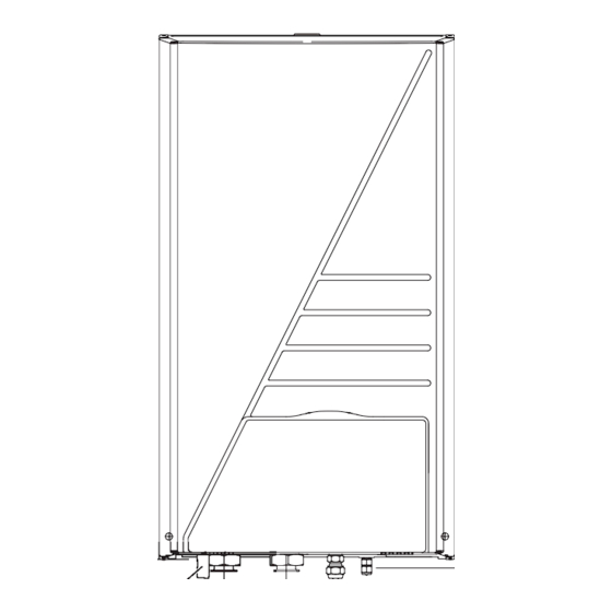
Page 14: Installation Of The Indoor Unit
NSTALLATION OF THE INDOOR UNIT Dimensions and service space Unit of measurement: mm Selecting an installation location Dimensions of the unit, see figure 2 The unit is to be wall mounted in an indoor location that meets the Flexible drain hose Refrigerant gas following requirements: connection... -
Page 15: Mounting The Indoor Unit
Mounting the indoor unit Installation of the EKHBDP drain pan kit (only for EKHBX models) CAUTION For heating/cooling models, it is necessary to install the drain pan kit (see "Accessories" on page The weight of the indoor unit is approximately 46 kg. Two persons are required to mount the unit. -
Page 16: Water Pipework
Checking the water volume and expansion vessel Water pipework pre-pressure The unit is equipped with an expansion vessel of 10 litre which has a Checking the water circuit default pre-pressure of 1 bar. The units are equipped with a water inlet and water outlet for To assure proper operation of the unit, the pre-pressure of the connection to a water circuit. - Page 17 Using the table and instructions below, determine if the total Example 2 water volume in the installation is below the maximum allowed The indoor unit is installed at the highest point in the water circuit. water volume. The total water volume in the water circuit is 350 l. Result: Installation Water volume...
-
Page 18: Charging Water
Charging water Field wiring Connect the water supply to a drain and fill valve (see "Main WARNING components" on page 10). A main switch or other means for disconnection, Make sure the automatic air purge valve is open (at least 2 having a contact separation in all poles, must be turns). - Page 19 M1P....Pump Required M2S..##..2-way valve for cooling mode (field supply) number of Maximum Item Description conductors running current M3S..#..3-way valve: floor heating/domestic hot water Power supply cable for outdoor 2+GND PHC1 ....Optocoupler input circuit unit Q1DI....Earth leakage circuit breaker (field supply) Indoor unit power supply and 3+GND Q1L ....Thermal protector backup heater...
- Page 20 Connection of the thermostat cable When routing out cables, make sure that these do not obstruct mounting of the indoor unit cover, see figure Connection of the thermostat cable depends on the application. Note: only relevant field wiring is shown. See also "Typical application examples"...
- Page 21 Wiring the 3-way valve CAUTION Using the appropriate cable, connect the valve control cable to the appropriate terminals as shown on the wiring diagram. For a benefit kWh rate power supply like illustrated below as type 1 NOTE Two types of 3-way valves can be connected. If the benefit kWh rate power supply is of the type that Wiring is different for each type: power supply is not interrupted, then control of the...
- Page 22 Mounting When the outdoor unit is connected to a benefit kWh rate power supply, the voltage free contact of the receiver controlling the benefit kWh rate signal of the electricity company must be connected to NOTE The digital controller has to be mounted indoors. clamps 17 and 18 of X2M (as illustrated in the figure above).
-
Page 23: Start-Up And Configuration
TART UP AND CONFIGURATION When the room thermostat is connected to the indoor unit, the heating and cooling schedule timers are The indoor unit should be configured by the installer to match the never available. Other schedule timers are not installation environment (outdoor climate, installed options, etc.) and affected. -
Page 24: Pump Operation Configuration
Pump operation configuration Domestic hot water tank installation configuration When no domestic hot water tank is NOTE To set the pump speed, refer to "Setting the pump installed, toggle switch SS2-2 should be set to speed" on page OFF (default). Without room thermostat: DIP switch SS2-3 = OFF When a domestic hot water tank is installed, When no thermostat is connected to the indoor unit, pump operation... -
Page 25: Powering Up The Indoor Unit
Internal wiring Field settings Visually check the switch box on loose connections or damaged electrical components. The indoor unit shall be configured by the installer to match the installation environment (outdoor climate, installed options, etc.) and Fixation user demand. Thereto, a number of so called field settings are Check that the unit is properly fixed, to avoid abnormal noises available. - Page 26 Detailed description [2] Disinfection function Applies only to installations with a domestic hot water tank. [0] User permission level The disinfection function disinfects the domestic hot water tank by If required, certain user interface buttons can be made unavailable for periodically heating the domestic hot water to a specific temperature.
- Page 27 [4] Backup/booster heater operation and space heating off [4-03]=1, then booster heater heater operation is only temperature determined by booster heater OFF temperature (T BH OFF booster heater ON temperature (T ) and/or schedule BH ON Backup heater operation timer. Refer to setting "[7-00]"...
- Page 28 Space heating priority temperature Applies only to installations [6] DT for heat pump domestic water heating mode — with a domestic hot water tank. The 'space heating priority — Applies only to installations with a domestic hot water tank. temperature' field settings apply to operation of the 3-way valve and the booster heater in the domestic hot water tank.
- Page 29 [7] DT for booster heater and dual set point control [7-01] Hysteresis value booster heater: temperature difference determining the booster heater ON temperature DT for booster heater ). T – [7-01] BH ON BH ON BH OFF Applies only to installations with a domestic hot water tank. minimum value booster...
- Page 30 [8] Domestic water heating mode timer [8-03] Booster heater delay time: specifies the start-up time delay of the booster heater operation when heat pump Applies only to installations with a domestic hot water tank. domestic water heating mode is active. The 'domestic water heating mode timer' field settings defines the When heat pump is active in domestic water minimum and maximum domestic water heating times, minimum time...
- Page 31 —based on the outdoor temperature— which heating The purpose of this field setting is to prevent the user from selecting source can/will provide the space heating, either the Daikin indoor a wrong (i.e., too hot or too cold) leaving water temperature. Thereto unit or an auxiliary boiler.
- Page 32 Local shift value weather dependent The combination of setting [4-03]=0/2 with The local shift value weather dependent field setting is only relevant bivalent operation at low outdoor temperature in case weather dependent set point (see field setting "[1] Weather can result in domestic hot water shortage. dependent set point (heating operation only)"...
- Page 33 [F] Option setup Pump operation The pump operation field setting apply to the pump operation logic only when DIP switch SS2-3 is OFF. When the pump operation function is disabled the pump will stop if the outdoor temperature is higher than the value set by [4-02] or if the outdoor temperature drops below the value set by [F-01].
-
Page 34: Field Settings Table
Field settings table Installer setting at variance with default value First Second Default code code Setting name Date Value Date Value value Range Step Unit User permission level User permission level — Weather dependent set point Low ambient temperature (Lo_A) –10 –20~5 °C... - Page 35 Installer setting at variance with default value First Second Default code code Setting name Date Value Date Value value Range Step Unit Heating and cooling set point ranges Heating set point upper limit 37~55 °C Heating set point lower limit 15~37 °C Cooling set point upper limit...
-
Page 36: Test Run And Final Check
EST RUN AND FINAL CHECK AINTENANCE AND SERVICE The installer is obliged to verify correct operation of the indoor and In order to ensure optimal availability of the unit, a number of checks outdoor unit after installation. and inspections on the unit and the field wiring have to be carried out at regular intervals. -
Page 37: Troubleshooting
The described checks must be executed at least once a year. ROUBLESHOOTING Water pressure This section provides useful information for diagnosing and Check if the water pressure is above 1 bar. If necessary add correcting certain troubles which may occur in the unit. water. -
Page 38: General Symptoms
Symptom 5: The water pressure relief valve leaks General symptoms OSSIBLE CAUSES ORRECTIVE ACTION Dirt is blocking the water pressure Check for correct operation of the Symptom 1: The unit is turned on (y LED is lit) but the unit is not relief valve outlet. -
Page 39: Error Codes
Error codes Error code Failure cause Corrective action Backup heater thermal protector Reset the thermal protector by When a safety device is activated, the user interface LED will be is open pressing the reset button (refer flashing, and an error code will be displayed. "Main components"... - Page 40 Error code Failure cause Corrective action Electric component failure Contact your local dealer. PCB failure Contact your local dealer. Electric component failure Contact your local dealer. Failure of capacity setting Contact your local dealer. Refrigerant failure (due to Contact your local dealer. refrigerant leak) Main circuit voltage failure Contact your local dealer.
-
Page 41: Technical Specifications
ECHNICAL SPECIFICATIONS General Heating/cooling models (EKHBX) Heating only models (EKHBH) Nominal capacity • cooling Refer to the Technical Data • heating Refer to the Technical Data Dimensions H x W x D 922 x 502 x 361 922 x 502 x 361 Weight •... - Page 42 4PW54185-1B...
Need help?
Do you have a question about the EKHBX008BA Series and is the answer not in the manual?
Questions and answers