Table of Contents
Advertisement
Advertisement
Table of Contents

Subscribe to Our Youtube Channel
Related Manuals for DMC BT-ST-302DR


Summary of Contents for DMC BT-ST-302DR
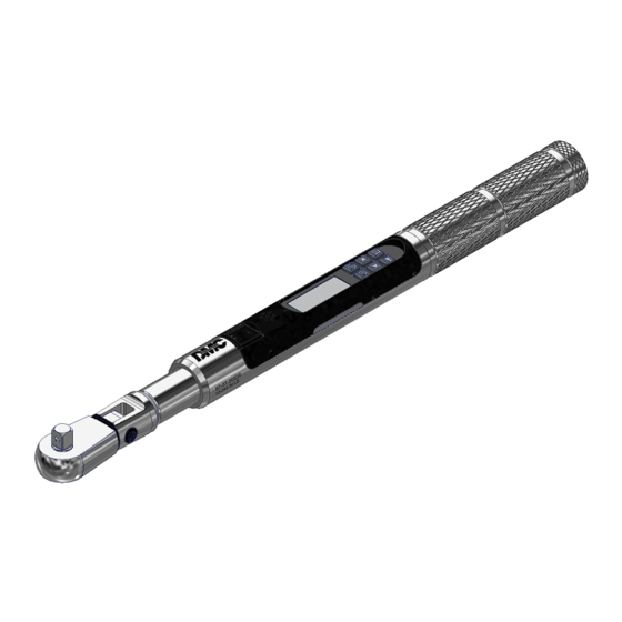
- Page 1 BT-ST-302DR ELECTRONIC TORQUE-ANGLE WRENCH...
-
Page 2: Important Safety Instructions
Electrical shock can cause injury. Metal handle is not isolated. Do not use on live electrical circuits. SAVE THESE INSTRUCTIONS Disclaimer Operation of BT-ST-302DR is not warranted in an EU member state if operating instructions are not in that State’s language. Contact DMC if a translation is needed. -
Page 3: Specifications
Specifications Head Type Square drive 72 teeth, sealed flex and fixed ratchet Fixed 3/8" square drive Reversed Head Design Display DISPLAY TYPE: Dot Matrix LCD (168 x 48 Resolution) VIEWING ANGLE: 6:00 BACKLIGHT: WHITE (LED) Sealed Button Pad POWER - ON/OFF and torque and angle re-zero ENTER - measurement mode select and menu entry... - Page 4 POWER button while wrench is on a stable surface with no torque applied. 1. Turn On Wrench. While holding wrench still, momentarily press POWER button. DMC logo will be displayed followed by torque and angle re-zeroing screens (if angle mode has been previously selected).
- Page 5 Note: If wrench is powered up in torque only measurement mode, angle is not zeroed until mode is changed to angle measurement mode, at which time torque and angle zeroing begins automatically after 2 seconds. Wrench should be placed on a stable surface with no torque applied.
- Page 6 Torque and Angle Mode Cycle Counting 1. Numerical counter located in top right of target torque or target angle screen will increment after each torque or angle cycle if applied torque or angle has reached target value. 2. When toggling between torque mode or angle mode using ENTER button or if target is changed, numerical counter will reset back to 00.
- Page 7 CLEAR DATA - Clears stored torque and angle data. CYCLE COUNT - Displays torque/angle cycle count screen. LANGUAGE - Displays language selection menu. SETTINGS - Displays advanced settings menu (see Advanced Settings Section). CONFIGURE - Displays advanced configuration menu (see Advanced Configuration Section). Setting Head Length Note: If wrench has an interchangeable head or an adapter or extension is added, length of head, adapter and/or extension being used can be entered to correct for a different length than head...
- Page 8 Use of Negative Offsets Note: Enter a negative value for offset when used in reverse direction with flex head or when calculating sum of interchangeable head and offset lengths. ������������ When length of an offset (or sum of head minus offset for interchangeable head) is negative, maximum fastener target is limited by following formulas: 240 in-lb wrench: Maximum Target Torque = offset * 24 + 240...
-
Page 9: Clear Data
Deleting Stored Torque and Angle Data 1. From target torque or angle screen, press and hold ENTER button for 3 seconds. 2. Highlight CLEAR DATA menu selection using UP/DOWN buttons then press ENTER button to display CLEAR ALL DATA screen. 3. - Page 10 ENTER EXIT button SET HEAD LENGTH held 100.0 IN-LB SHOW DATA Target Screen UP/DOWN buttons Decimal Mark Selection menu Language Selection menu ENTER ENTER DECIMAL MARK CLEAR DATA ENGLISH button button COMMA (1,23) CYCLE COUNT FRANCAIS POINT (1.23) LANGUAGE ESPANOL UP/DOWN buttons DECIMAL MARK ENTER button...
- Page 11 range by pressing UP/DOWN buttons. Once desired minimum torque value has been set, press ENTER button. 6. MAXIMUM TORQUE screen is displayed next. MAXIMUM TORQUE is torque value above which red progress lights turn on. Initial MAXIMUM TORQUE value will be TARGET TORQUE value plus positive torque tolerance (default 4%, see MODE SETUP in Advanced Configuration section).
- Page 12 8. To enter additional angle presets, repeatedly press ENTER button until target angle screen is displayed and repeat steps above. UNIT ADD PRESET button held 90° Target Angle Screen UP/DOWN buttons UP/DOWN buttons UP/DOWN buttons ENTER ENTER ADD PRESET TARGET ANGLE MINIMUM ANGLE button button...
-
Page 13: Advanced Settings
UNIT PSET 02 DELETE button held EDIT 92° EXIT Preset Angle Screen UP/DOWN buttons DELETE EDIT ENTER button EXIT ENTER button 100.0 IN-LB Target Torque Screen Note: Pressing ENTER button while EXIT menu selection is highlighted will exit without deleting PSET. Note: When a PSET is deleted, all other stored PSET’s will retain their original PSET numbers. -
Page 14: Sleep Time
3. UP/DOWN buttons are used to scroll screen. Operational Information: SN: Serial number assigned to wrench. CAL: Date of last wrench calibration. ISD: In-Service Date. TCF: Torque Calibration Factor. ACF: Angle Calibration Factor. VER: Software version. ... -
Page 15: Lcd Contrast
Setting LCD Contrast This function will allow user to set LCD contrast for optimal viewing. 1. From Settings menu, use UP/DOWN buttons to highlight LCD CONTRAST selection then press ENTER button. 2. CONTRAST screen is displayed. 3. Use UP/DOWN buttons while viewing display to change contrast to desired level. Selectable levels: 20 to 80 in increments of 5 (factory default = 40). - Page 16 4. Press ENTER button to accept selection and exit to Settings menu. EXIT SHOW INFO SLEEP TIME UP/DOWN buttons ENTER LCD CONTRAST AUTO BACKLIGHT button KEY BEEP ENABLE AUTO BACKLIGHT DISABLE UP/DOWN buttons AUTO BACKLIGHT ENABLE ENTER DISABLE button Toggle Backlight Setup This function will allow user to enable or disable backlight toggle function.
-
Page 17: Battery Type
EXIT SHOW INFO SLEEP TIME UP/DOWN buttons ENTER AUTO BACKLIGHT VIBRATOR CONFIG button TOGGLE BCKLGHT ENABLE VIBRATOR CONFIG DISABLE UP/DOWN buttons VIBRATOR CONFIG ENABLE ENTER DISABLE button Battery Type Selection This function will allow user to configure the battery discharge thresholds for the type of battery used. 1. -
Page 18: Advanced Configuration
Advanced Configuration Accessing Advanced Configuration Advanced configuration is accessed from CONFIGURE menu selection on main menu. Note: If wrench has been locked (see Preset Lock and Job Mode), a password entry is required to enter Configure menu. 1. From target torque or angle screen, press and hold ENTER button for 3 seconds. 2. - Page 19 Setting Target Tolerances This function will allow user to set plus and minus tolerances for torque and angle targets. Note: These tolerances are used for manual modes only. Preset tolerances are defined by Minimum and Maximum values. 1. From Mode Setup menu, use UP/DOWN buttons to highlight tolerance selection to setup (TQ-%, TQ+%, ANG-% ANG+%) then press ENTER button.
- Page 20 1. From target torque screen, use UP/DOWN buttons to set target torque and UNITS button to select torque measurement units then press ENTER button. 2. Angle target screen is displayed. Use UP/DOWN buttons to set target angle then press ENTER button.
- Page 21 Torque AND Angle Mode Torque AND Angle mode is setup by first setting a target torque and units then a target angle before selecting Torque AND Angle mode. In Torque AND Angle mode, torque and angle are measured simultaneously. Yellow progress lights track torque measurement. When both torque and angle reach their targets, green progress lights turn on and torque and angle data record is stored.
-
Page 22: Delete Preset
Note: If LOCK is selected without a Preset configured, following screen is displayed: NO PRESETS PRESS Note: When Preset Lock is enabled, Clear Memory function is disabled and displays following Locked CONT. message if attempted: LOCKED PRESS TO CONT. Note: When Preset Lock is enabled, Clear Cycle count function is disabled and displays Locked message if attempted. -
Page 23: Job Mode
Job Mode function allows user to enable or disable wrench preset Job mode. When in Job mode, wrench executes presets in order configured and automatically switches to next preset when batch count reaches zero. Wrench is locked and Preset lock icon is displayed when Job mode is enabled. Note: Password entry is required to enable Job Mode. - Page 24 Note: Hour selection will scroll through 0 to 23. Minute and Second selections will scroll through 0 to Note: If batteries are removed from wrench for longer than 20 minutes, clock will revert to default settings and must be re-entered at power on. ENTER ENTER ENTER...
- Page 25 torque is recalibrated, calibration counter is automatically reset to zero. User can disable calibration interval check and use number of cycles since last calibration to decide when to recalibrate. Note: If an invalid date is entered and Calibration interval is enabled, an unintended "CAL NEEDED" message may be displayed.
-
Page 26: Troubleshooting
Troubleshooting Note: If any of following issues persist, return wrench to Daniels Manufacturing Corporation. Issue Possible Cause Resolution Wrench does not turn on when Dead/No batteries Replace batteries POWER button pressed. Software glitch Cycle power using end-cap Torque reading out of spec. Calibration required Recalibrate Incorrect head length... -
Page 27: Maintenance & Service
When using wobble extension or a universal, do not exceed more than 15 degrees of offset from perpendicular drive. Do not use a long extension with flex-drive at full flex. CALIBRATION Contact your DMC sales representative for calibration services. CERTIFICATION This torque wrench was calibrated at factory using torque measurement instruments that are traceable to National Institute of Standards and Technology (N.I.S.T.). -
Page 28: Battery Replacement
Battery Replacement Note: When replacing battery, real-time-clock will maintain date and time for 20 minutes. Note: Turn End Cap counter-clockwise to unscrew. Battery should be installed in carrier prior to carrier installation into wrench. Battery negative contact should be oriented towards carrier spring. 100% BATTERY UNSCREW END CAP LEVEL... - Page 29 DMC’s obligation under this warranty is limited to the free correction or, at DMC’s option, the refund of the purchase price of any such product which proves defective in normal service within ninety (90) days after delivery to the first user, provided that the product is returned to DMC with all transportation charges prepaid and which shall appear to DMC’s satisfaction,...
- Page 30 Mouser Electronics Authorized Distributor Click to View Pricing, Inventory, Delivery & Lifecycle Information: Daniels Manufacturing BT-ST-302D...
Need help?
Do you have a question about the BT-ST-302DR and is the answer not in the manual?
Questions and answers