Table of Contents
Advertisement
Quick Links
Advertisement
Table of Contents

Related Manuals for Benewake TFmini-i


Summary of Contents for Benewake TFmini-i
- Page 1 TFmini-i User Manual...
- Page 2 Remember the precautions to avoid hazards, and please follow the described steps in the manual when using it. If you have any problems in the process of usage, you are welcome to contact Benewake at any time for help. Contact details Official website: en.benewake.com...
-
Page 3: Table Of Contents
CONTENTS ONEVIEW ............................1 1.1 Technical Specification ......................1 1.2 Maintenance and Cleaning ....................2 1.3 Appearance and Installation ....................2 1.4 Storage ............................. 3 1.5 Application ..........................4 INTERFACE ............................5 2.1 Description About Wiring Sequence .................. 5 2.2 Electrical Characteristics ....................... 5 COMMUNICATION PROTOCOL .................... -
Page 4: Oneview
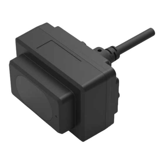
ONEVIEW ONEVIEW TFmini-i is an updated single-point ranging LiDAR based on TFmini-S. It has been optimized in communication interface and input voltage, making it satisfy different industrial applications. The product is based on the ToF (Time of Flight) principle and provides stable, accurate and reliable ranging performance. -
Page 5: Maintenance And Cleaning
to offer professional advice. Appearance and Installation The appearance and dimensions of TFmini-i are shown in Figure 1-1: Figure 1-1 Appearance and dimension of TFmini-i (Unit: mm) φ TFmini-i has four 1.6 mounting screw holes in the back, hole depth of 5mm, as shown in Figure 1-2. -
Page 6: Storage
For ensuring the product performance, do not open the product shell or remove the IR-pass filter. REV: 12/07/2022 · ©2022 Benewake (Beijing) Co., Ltd. | en.benewake.com | All rights reserved BP-UM-18 A02... -
Page 7: Application
If you use the product beyond the above application scope, please carefully evaluate whether the reliability requirements of the product to be applied match this product, or contact Benewake at any time to assist in solving it. REV: 12/07/2022 · ©2022 Benewake (Beijing) Co., Ltd. | en.benewake.com... -
Page 8: Interface
② Do not mix UART cable with RS485 or CAN bus, otherwise it will cause damage of MCU. ③ TFmini-i with RS-485 interface does not support UART debugging pins. Electrical Characteristics Table 2-2 Main Electrical Parameters of TFmini-i Parameter Values... -
Page 9: Communication Protocol
3.1.2 Parameter configuration description of Modbus protocol 3.1.2.1 Description of data frame When Modbus protocol of TFmini-i is enabled, the Modbus command format of reading distance is shown in Table 3-2. Table 3-2 The command format of reading distance Addr. - Page 10 COMMUNICATION PROTOCOL 3.1.2.2 Function code The function code of TFmini-i is shown in Table 3-4. Table 3-4 The function code Function Code Description Read register Write register 3.1.2.3 Register address list All register addresses are hexadecimal and register values are 16 bits;...
-
Page 11: Parameter Configuration
01 03 00 06 00 01 03 04 00 VM VS: Sub-version number version 02 24 0A VS VC CL CH VC: Revised version number REV: 12/07/2022 · ©2022 Benewake (Beijing) Co., Ltd. | en.benewake.com | All rights reserved BP-UM-18 A02... - Page 12 //Default address is 0x01, disable Modbus protocol 01 06 00 80 00 00 88 22 //Default address is 0x01, save setting Exit Modbus protocol after rebooting. REV: 12/07/2022 · ©2022 Benewake (Beijing) Co., Ltd. | en.benewake.com | All rights reserved BP-UM-18 A02...
-
Page 13: Can Communication Protocol
CAN Communication Protocol 3.2.1 Communication Protocol The CAN communication protocol of TFmini-i supports customer-defined protocol parameters or customized services, and the CAN protocol baud rate and ID can be modified. The CAN protocol is shown in Table 3-9. Table 3-9 CAN communication protocol of TFmini-i... -
Page 14: Parameter Configuration Of Can Communication
500kbps 100Hz 250kbps 100Hz Note It is recommended to contact Benewake to communicate the details of use to complete networking requirements. 3.2.4 Parameter Configuration of CAN Communication The configuration command format of CAN communication is shown as below. Table 3-12 The configuration command format... -
Page 15: Other Parameter Configuration
5A 05 60 01 C0 Enable 120Ω terminal resistor 120 Ω terminal 5A 05 60 00 BF 5A 05 60 00 BF Disable 120Ω terminal resistor resistor ⑤ REV: 12/07/2022 · ©2022 Benewake (Beijing) Co., Ltd. | en.benewake.com | All rights reserved BP-UM-18 A02... - Page 16 After parameters configuration, send saving settings command to save the configuration, otherwise the settings will not take effect. ⑤ 120Ω terminal resistor is disable in default. REV: 12/07/2022 · ©2022 Benewake (Beijing) Co., Ltd. | en.benewake.com | All rights reserved BP-UM-18 A02...
Need help?
Do you have a question about the TFmini-i and is the answer not in the manual?
Questions and answers