Table of Contents
Advertisement
Quick Links
Advertisement
Table of Contents

Related Manuals for EWM Tetrix 351 Classic FW


Summary of Contents for EWM Tetrix 351 Classic FW
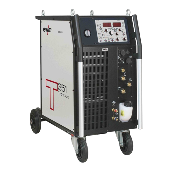
- Page 1 Operating instructions Welding machine Tetrix 351 Classic FW Tetrix 401 Classic FW Tetrix 451 Classic FW Tetrix 551 Classic FW 099-000088-EW501 26.11.2012 Register now! For your benefit Jetzt Registrieren und Profitieren! www.ewm-group.com...
- Page 2 © EWM HIGHTEC WELDING GmbH · Dr. Günter-Henle-Str. 8 · D-56271 Mündersbach, Germany The copyright to this document remains the property of the manufacturer.
-
Page 3: Table Of Contents
Contents Notes on the use of these operating instructions Contents 1 Contents..............................3 2 Safety instructions..........................7 Notes on the use of these operating instructions ................7 Explanation of icons........................8 General ............................9 Transport and installation ......................13 2.4.1 Lifting by crane ......................14 Ambient conditions........................ - Page 4 Contents Notes on the use of these operating instructions 5.7.8 Function sequences/operating modes................36 5.7.8.1 Explanation of symbols .................36 5.7.8.2 Non-latched mode ..................37 5.7.8.3 Latched mode....................38 5.7.8.4 spotArc ......................39 5.7.8.5 Spotmatic ......................41 5.7.8.6 Non-latched operation, version C..............42 5.7.9 Pulses, function sequences ..................43 5.7.9.1 TIG pulses –...
- Page 5 Tetrix 401 FW ..........................79 Tetrix 351, 451, 551 FW ......................80 9 Accessories ............................81 Remote controls and accessories....................81 Options............................81 General accessories ........................82 Computer communication......................82 10 Appendix A ............................83 10.1 Overview of EWM branches ......................83 099-000088-EW501 26.11.2012...
- Page 6 Contents Notes on the use of these operating instructions 099-000088-EW501 26.11.2012...
-
Page 7: Safety Instructions
Safety instructions Notes on the use of these operating instructions Safety instructions Notes on the use of these operating instructions DANGER Working or operating procedures which must be closely observed to prevent imminent serious and even fatal injuries. • Safety notes include the "DANGER" keyword in the heading with a general warning symbol. •... -
Page 8: Explanation Of Icons
Safety instructions Explanation of icons Explanation of icons Symbol Description Press Do not press Turn Switch Switch off machine Switch on machine ENTER (enter the menu) NAVIGATION (Navigating in the menu) EXIT (Exit the menu) Time display (example: wait 4s/press) Interruption in the menu display (other setting options possible) Tool not required/do not use Tool required/use... -
Page 9: General
Safety instructions General General DANGER Electric shock! Welding machines use high voltages which can result in potentially fatal electric shocks and burns on contact. Even low voltages can cause you to get a shock and lead to accidents. • Do not touch any live parts in or on the machine! •... - Page 10 Safety instructions General WARNING Explosion risk! Apparently harmless substances in closed containers may generate excessive pressure when heated. • Move containers with inflammable or explosive liquids away from the working area! • Never heat explosive liquids, dusts or gases by welding or cutting! Smoke and gases! Smoke and gases can lead to breathing difficulties and poisoning.
- Page 11 Safety instructions General CAUTION Obligations of the operator! The respective national directives and laws must be observed for operation of the machine! • National implementation of the framework directive (89/391/EWG), as well as the associated individual directives. • In particular, directive (89/655/EWG), on the minimum regulations for safety and health protection when staff members use equipment during work.
- Page 12 Safety instructions General CAUTION EMC Machine Classification In accordance with IEC 60974-10, welding machines are grouped in two electromagnetic compatibility classes (see technical data): Class A machines are not intended for use in residential areas where the power supply comes from the low-voltage public mains network.
-
Page 13: Transport And Installation
Safety instructions Transport and installation Transport and installation WARNING Incorrect handling of shielding gas cylinders! Incorrect handling of shielding gas cylinders can result in serious and even fatal injury. • Observe the instructions from the gas manufacturer and in any relevant regulations concerning the use of compressed air! •... -
Page 14: Lifting By Crane
Safety instructions Transport and installation 2.4.1 Lifting by crane DANGER Risk of injury during lifting by crane! When lifting the equipment by crane, serious injuries can be inflicted by falling equipment or add-on units. • Transport on all lifting lugs at the same time (see Fig. -
Page 15: Ambient Conditions
Safety instructions Ambient conditions Ambient conditions CAUTION Installation site! The machine must not be operated in the open air and must only be set up and operated on a suitable, stable and level base! • The operator must ensure that the ground is non-slip and level, and provide sufficient lighting for the place of work. -
Page 16: Intended Use
3.1.1.1 activArc The EWM activArc process, thanks to the highly dynamic controller system, ensures that the power supplied is kept virtually constant in the event of changes in the distance between the welding torch and the weld pool, e.g. during manual welding. Voltage losses as a result of a shortening of the distance between the torch and molten pool are compensated by a current rise (ampere per volt - A/V), and vice versa. -
Page 17: Documents Which Also Apply
Intended use Documents which also apply Documents which also apply 3.2.1 Warranty NOTE For further information, please see the accompanying supplementary sheets "Machine and Company Data, Maintenance and Testing, Warranty"! 3.2.2 Declaration of Conformity The designated machine conforms to EC Directives and standards in terms of its design and construction: •... -
Page 18: Machine Description - Quick Overview
Machine description – quick overview Front view Machine description – quick overview NOTE The maximum possible machine configuration is given in the text description. If necessary, the optional connection may need to be retrofitted (see "Accessories" chapter). Front view Figure 4-1 099-000088-EW501 26.11.2012... - Page 19 Machine description – quick overview Front view Item Symbol Description Lifting lug Main switch, machine on/off Machine control See Machine control – operating elements chapter Carrying handle Automatic cut-out of coolant pump key button press to reset a triggered fuse Quick connect coupling (red) coolant return Quick connect coupling (blue)
-
Page 20: Rear View
Machine description – quick overview Rear view Rear view Figure 4-2 099-000088-EW501 26.11.2012... - Page 21 Machine description – quick overview Rear view Item Symbol Description 7-pole connection socket (digital) For connecting digital accessory components PC interface, serial (D-Sub connection socket, 9-pole) 19-pole mechanised welding interface (analogue) (See chapter entitled "Design and function > interfaces".) analog Ignition type changeover switch Liftarc (contact ignition) HF ignition...
-
Page 22: Machine Control - Operating Elements
Machine description – quick overview Machine control – Operating elements Machine control – Operating elements Figure 4-3 Item Symbol Description Welding process button MMA welding, lights up in green / arcforce setting, lights up in red TIG welding Operating mode button spotArc (spot time setting range 0.01 sec. -
Page 23: Function Sequence
Machine description – quick overview Machine control – Operating elements 4.3.1 Function sequence Figure 4-4 Item Symbol Description Gas and current parameters button Gas pre-flow time / gas test / gas rinsing (TIG) Gas pre-flows: Setting range 0.0 sec to 20.0 sec (0.1s increments). Gas test: Shielding gas flows up to 20 sec. - Page 24 Machine description – quick overview Machine control – Operating elements Item Symbol Description Signal light for secondary current downslope time (tS1)/pulse time (t1) • Downslope time (tS1): Period from main current AMP to secondary current AMP%. • Pulse time (t1): Main current phase (AMP) during pulses. See chapter "Advanced settings".
-
Page 25: Design And Function
Design and function General Design and function General WARNING Risk of injury from electric shock! Contact with live parts, e.g. welding current sockets, is potentially fatal! • Follow safety instructions on the opening pages of the operating instructions. • Commissioning may only be carried out by persons who have the relevant expertise of working with arc welding machines! •... -
Page 26: Workpiece Lead, General
Design and function Workpiece lead, general Workpiece lead, general CAUTION Risk of burns due to incorrect connection of the workpiece lead! Paint, rust and dirt on the connection restrict the power flow and may lead to stray welding currents. Stray welding currents may cause fires and injuries! •... -
Page 27: Adding Coolant
Design and function Welding torch cooling system 5.5.3 Adding coolant The unit is supplied ex works with a minimum level of coolant. NOTE After the initial filling, wait for at least one minute when the machine is switched on so that the tube package is filled with coolant completely and without bubbles. -
Page 28: Mains Connection
Design and function Mains connection Mains connection DANGER Hazard caused by improper mains connection! An improper mains connection can cause injuries or damage property! • Only use machine with a plug socket that has a correctly fitted protective conductor. • If a mains plug must be fitted, this may only be carried out by an electrician in accordance with the relevant national provisions or regulations! •... -
Page 29: Tig Welding
Design and function TIG welding TIG welding 5.7.1 Welding torch and workpiece line connection CAUTION Equipment damage due to improperly connected coolant lines! If the coolant lines are not connected or a gas-cooled welding torch is used, the coolant circuit is interrupted and equipment damage can occur. •... -
Page 30: Torch Connection Options And Pin Assignments
Design and function TIG welding Item Symbol Description Welding torch Welding torch hose package Connection socket, 8-pole TIG Up/Down or potentiometer torch control lead Connection socket, 5-pole Standard TIG torch control lead G¼” connecting nipple, “-” welding current Shielding gas connection (with yellow insulating cap) for TIG welding torch Connection socket, “-”... -
Page 31: Shielding Gas Supply (Shielding Gas Cylinder For Welding Machine)
Design and function TIG welding 5.7.3 Shielding gas supply (shielding gas cylinder for welding machine) WARNING Risk of injury due to improper handling of shielding gas cylinders! Improper handling and insufficient securing of shielding gas cylinders can cause serious injuries! •... -
Page 32: Connecting The Shielding Gas Supply
Design and function TIG welding 5.7.3.1 Connecting the shielding gas supply • Place the shielding gas cylinder into the relevant cylinder bracket. • Secure the shielding gas cylinder using a securing chain. Figure 5-5 Item Symbol Description Pressure regulator Shielding gas cylinder Output side of the pressure regulator Cylinder valve •... -
Page 33: Setting The Shielding Gas Quantity
Design and function TIG welding 5.7.3.2 Setting the shielding gas quantity NOTE Rule of thumb for the gas flow rate: Diameter of gas nozzle in mm corresponds to gas flow in l/min. Example: 7mm gas nozzle corresponds to 7l/min gas flow. Incorrect shielding gas setting! If the shielding gas setting is too low or too high, this can introduce air to the weld pool and may cause pores to form. -
Page 34: Automatic Gas Post-Flow
Design and function TIG welding 5.7.3.5 Automatic gas post-flow When the automatic gas post-flow function is activated, the gas post-flow time is defined by the machine control depending on the application (4.0 s to 40.0 s). The gas post-flow time can be adjusted if necessary on the machine control. -
Page 35: Arc Ignition
Design and function TIG welding 5.7.6 Arc ignition 5.7.6.1 HF ignition Figure 5-6 The arc is started without contact from high-voltage ignition pulses. a) Position the welding torch in welding position over the workpiece (distance between the electrode tip and workpiece should be approx. 2-3mm). b) Press the torch trigger (high voltage ignition pulses ignite the arc). -
Page 36: Function Sequences/Operating Modes
Design and function TIG welding 5.7.8 Function sequences/operating modes The parameters for the function sequence are set using the “Select welding parameters” button and the “Welding parameter setting” rotary dial. Figure 5-8 Item Symbol Description Slope times button/select expert menu •... -
Page 37: Non-Latched Mode
Design and function TIG welding 5.7.8.2 Non-latched mode Figure 5-9 1st cycle: • Press and hold torch trigger 1. • The gas pre-flow time elapses. • HF ignition pulses jump from the electrode to the workpiece, the arc ignites. • The welding current flows and immediately assumes the value set for the ignition current I start •... -
Page 38: Latched Mode
Design and function TIG welding 5.7.8.3 Latched mode AMP% start Down Figure 5-10 Step 1 • Press torch trigger 1, the gas pre-flow time elapses. • HF ignition pulses jump from the electrode to the workpiece, the arc ignites. • Welding current flows and immediately assumes the ignition current value set (search arc at minimum setting). -
Page 39: Spotarc
Design and function TIG welding 5.7.8.4 spotArc The TIG SpotArc function is activated with the pulse variant automated frequencies by default, because this combination produces the most effective results. Selecting and setting TIG spotArc Operating Action Result element Signal light comes on The spot time can be set for approx. - Page 40 Design and function TIG welding Sequence: • Press and hold torch trigger 1. • The gas pre-flow time elapses. • HF ignition pulses jump from the electrode to the workpiece, the arc ignites. • The welding current flows and immediately assumes the value set for the ignition current I start •...
-
Page 41: Spotmatic
Design and function TIG welding 5.7.8.5 Spotmatic The arc is ignited fully automatically without actuating the torch trigger by simply touching the tip of the electrode with the workpiece. Hundreds of reproducible tacks can be made without tungsten inclusions. NOTE Selection and adjustment are made in the same way as with spotArc operating mode (see chapter TIG spotArc). -
Page 42: Non-Latched Operation, Version C
Design and function TIG welding 5.7.8.6 Non-latched operation, version C Figure 5-13 1st cycle • Press torch trigger 1, the gas pre-flow time elapses. • HF ignition pulses jump from the electrode to the workpiece, the arc ignites. • Welding current flows and immediately adopts the ignition current value set (search arc at minimum setting). -
Page 43: Pulses, Function Sequences
Design and function TIG welding 5.7.9 Pulses, function sequences NOTE The function sequences in pulses basically behave in the same way as in standard welding, but during the main current phase there is a continual switching back and forth between the pulse and pause currents at the relevant times. The pulse function can also be deactivated if necessary during the upslope and downslope phases (see chapter "Advanced settings"). -
Page 44: 5.7.10 Tig Activarc Welding
TIG welding 5.7.10 TIG activArc welding The EWM activArc process, thanks to the highly dynamic controller system, ensures that the power supplied is kept virtually constant in the event of changes in the distance between the welding torch and the weld pool, e.g. during manual welding. Voltage losses as a result of a shortening of the distance between the torch and molten pool are compensated by a current rise (ampere per volt - A/V), and vice versa. -
Page 45: Welding Torch (Operating Variants)
Design and function TIG welding 5.7.11 Welding torch (operating variants) Different torch versions can be used with this machine. Functions on the operating elements, such as torch triggers (TT), rockers or potentiometers, can be modified individually via torch modes. Explanation of symbols for operating elements: Symbol Description Press torch trigger... -
Page 46: 5.7.12 Torch Mode And Up/Down Speed Setting
Design and function TIG welding 5.7.12 Torch mode and up/down speed setting The user has the modes 1 to 6 and modes 11 to 16 available. Modes 11 to 16 include the same function options as 1 to 6, but without tapping function for the secondary current. The function options in the individual modes can be found in the tables for the corresponding torch types. -
Page 47: Standard Tig Torch (5-Pole)
Design and function TIG welding 5.7.12.1 Standard TIG torch (5-pole) Standard torch with one torch trigger: Diagram Operating Explanation of symbols elements BRT1 = Torch trigger 1 (welding current on/off; secondary current via tapping function) Functions mode Operating elements BRT 1 Welding current On/Off (factory-set) BRT 1... - Page 48 Design and function TIG welding Standard torch with one rocker (MG rocker, two torch triggers) Diagram Operating Explanation of symbols elements BRT 1 = torch trigger 1 BRT 2 = torch trigger 2 Functions mode Operating elements BRT 1 Welding current On/Off Secondary current BRT 2 (factory-set)
-
Page 49: Tig Up/Down Torch (8-Pole)
Design and function TIG welding 5.7.12.2 TIG up/down torch (8-pole) Up/down torch with one torch trigger Diagram Operating Explanation of symbols elements TT 1 = torch trigger 1 Functions Mode Operating elements BRT 1 Welding current on/off BRT 1 Secondary current (tapping mode) / (latched mode) (factory- set) Increase welding current, infinite adjustment (up function) - Page 50 Design and function TIG welding Up/down torch with two torch triggers Diagram Operating Explanation of symbols elements TT 1 = torch trigger 1 (left) TT 2 = torch trigger 2 (right) Functions Mode Operating elements BRT 1 Welding current on/off BRT 2 Secondary current BRT 1...
-
Page 51: Potentiometer Torch (8-Pole)
Design and function TIG welding 5.7.12.3 Potentiometer torch (8-pole) NOTE The welding machine needs to be configured for operation with a potentiometer torch (see chap. "Configuring TIG potentiometer torch") Potentiometer torch with one torch trigger: Diagram Operating Explanation of symbols elements BRT 1 = torch trigger 1 Functions... -
Page 52: 5.7.12.4 Setting The First Increment
Design and function TIG welding 5.7.12.4 Setting the first increment Figure 5-17 Figure 5-18 Display Setting/selection Exit the menu Exit Torch configuration menu Set welding torch functions Setting the first increment Setting: 1 to 20 (factory setting 1) NOTE This function is only available when using up/down torches in modes 4 and 14! 099-000088-EW501 26.11.2012... -
Page 53: Mma Welding
Design and function MMA welding MMA welding CAUTION Risk of being crushed or burnt. When replacing spent or new stick electrodes • Switch off machine at the main switch • Wear appropriate safety gloves • Use insulated tongs to remove spent stick electrodes or to move welded workpieces and •... -
Page 54: Select Welding Task
Design and function MMA welding Item Symbol Description Electrode holder Connection socket, “-” welding current Electrode holder connection Workpiece Connection socket, “+” welding current Connection for workpiece lead • Insert cable plug of the electrode holder into either the "+" or "-" welding current connection socket and lock by turning to the right. -
Page 55: Hotstart Current And Hotstart Time
Design and function MMA welding 5.8.3 Hotstart current and Hotstart time The hotstart device improves the ignition of the stick electrodes using an increased ignition current. a) = Hotstart time b) = Hotstart current Welding current Time Operating Action Result Displays element Select hotstart current welding parameter... -
Page 56: Remote Control
Design and function Remote control Remote control NOTE Insert the remote control control cable into the 19-pole connection socket for remote control connection and lock. 5.9.1 Manual remote control RT1 19POL Functions • Infinitely adjustable welding current (0% to 100%) depending on the preselected main current on the welding machine. -
Page 57: Foot-Operated Remote Control Rtf1 19Pol
Design and function Remote control 5.9.6 Foot-operated remote control RTF1 19POL Functions • Infinitely adjustable welding current (0% to 100%) depending on the preselected main current on the welding machine. • Start/stop welding operation (TIG) ActivArc welding is not possible in combination with the RTF 1 foot-operated remote control. FFr >... -
Page 58: Interfaces For Automation
Design and function Interfaces for automation 5.10 Interfaces for automation CAUTION Damage to the machine due to improper connection! Unsuitable control leads or incorrect connection of input and output signals can cause damage to the machine. • Only use shielded control leads! •... -
Page 59: 5.10.2 Tig Interface For Mechanised Welding
Design and function Interfaces for automation 5.10.2 TIG interface for mechanised welding NOTE These accessory components can be retrofitted as an option, see Accessories chapter. Signal Designation Diagram shape Output Connection for cable screen Output REGaus For servicing purposes only Input SYN_E Synchronisation for master/slave operation... -
Page 60: Pc Interfaces
Design and function PC Interfaces 5.11 PC Interfaces CAUTION Equipment damage or faults may occur if the PC is connected incorrectly! Not using the SECINT X10USB interface results in equipment damage or faults in signal transmission. The PC may be destroyed due to high frequency ignition pulses. •... -
Page 61: Advanced Settings
Design and function Advanced settings 5.12 Advanced settings 5.12.1 Setting slope times for secondary current AMP% or pulse edges Figure 5-23 Figure 5-24 Display Setting/selection Slope time tS1 (main current to secondary current) Setting: 0.00 s to 20.0 s (factory setting 0.01 s) Slope time tS2 (secondary current to main current) Setting: 0.00 s to 20.0 s (factory setting 0.01 s) 099-000088-EW501... -
Page 62: 5.12.2 Tig Non-Latched Operating Mode, C Version
Design and function Advanced settings 5.12.2 TIG non-latched operating mode, C version Figure 5-25 Display Setting/selection Exit the menu Exit Machine configuration Settings for machine functions and parameter display Non-latched operation (C version) • on = on • off = off (factory setting) 099-000088-EW501 26.11.2012... -
Page 63: 5.12.3 Configuring The Tig Potentiometer Torch Connection
Design and function Advanced settings 5.12.3 Configuring the TIG potentiometer torch connection DANGER Risk of injury due to electrical voltage after switching off! Working on an open machine can lead to fatal injuries! Capacitors are loaded with electrical voltage during operation. Voltage remains present for up to four minutes after the mains plug is removed. -
Page 64: Welding Current Display (Ignition, Secondary, End And Hotstart Currents)
Design and function Advanced settings 5.12.4 Welding current display (ignition, secondary, end and hotstart currents) The welding currents for secondary current, ignition current and end current (expert menu) can be displayed as percentages (factory setting) or absolute values on the machine display. Figure 5-27 Display Setting/selection... -
Page 65: Ramp Function Foot-Operated Remote Control Rtf 1
Design and function Advanced settings 5.12.5 Ramp function foot-operated remote control RTF 1 Figure 5-28 Display Setting/selection Exit the menu Exit Machine configuration Settings for machine functions and parameter display Ramp function Remote control RTF 1 The ramp function can be switched on and off Switch on Switching on machine function Switch off... -
Page 66: Menus And Sub-Menus On The Machine Control
Design and function Menus and sub-menus on the machine control 5.13 Menus and sub-menus on the machine control 5.13.1 Direct menus (direct access to parameters) Functions, parameters and their values can be accessed directly, e.g. can be selected by pressing a button once. -
Page 67: 5.13.3 Machine Configuration Menu
Design and function Menus and sub-menus on the machine control 5.13.3 Machine configuration menu NOTE ENTER (enter the menu) • Switch off machine at the main switch • Press and hold the "welding parameters" button and switch the machine on again at the same time. - Page 68 Design and function Menus and sub-menus on the machine control Display Setting/selection Exit the menu Exit Torch configuration menu Set welding torch functions Torch mode (factory setting 1) Setting the first increment Setting: 1 to 20 (factory setting 1) Up-/Down speed Increase value = rapid current change (factory setting 10) Reduce value...
- Page 69 Design and function Menus and sub-menus on the machine control Display Setting/selection Orbital welding • off = off (ex works) • on = on Orbital welding Correction value for orbital current Service menu Modifications to the service menu may only be carried out by authorised maintenance staff! Reset (reset to factory settings) •...
-
Page 70: Maintenance, Care And Disposal
Maintenance, care and disposal General Maintenance, care and disposal DANGER Risk of injury from electric shock! Cleaning machines that are not disconnected from the mains can lead to serious injuries! • Disconnect the machine completely from the mains. • Remove the mains plug! •... -
Page 71: Maintenance Work
Information about giving back used equipment or about collections can be obtained from the respective municipal administration office. • EWM participates in an approved waste disposal and recycling system and is registered in the Used Electrical Equipment Register (EAR) under number WEEE DE 57686922. •... -
Page 72: Rectifying Faults
Rectifying faults Checklist for rectifying faults Rectifying faults All products are subject to rigorous production checks and final checks. If, despite this, something fails to work at any time, please check the product using the following flowchart. If none of the fault rectification procedures described leads to the correct functioning of the product, please inform your authorised dealer. - Page 73 Rectifying faults Checklist for rectifying faults No arc ignition Incorrect ignition type setting. Set ignition type changeover switch to the HF ignition setting. Bad arc ignition Material inclusions in the tungsten electrode due to contact with filler material or workpiece Regrind or replace the tungsten electrode Bad current transfer on ignition Check the setting on the "Tungsten electrode diameter/Ignition optimisation"...
-
Page 74: Error Messages (Power Source)
Rectifying faults Error messages (power source) Error messages (power source) NOTE A welding machine error is indicated by the collective fault signal lamp (A1) lighting up and an error code (see table) being displayed in the machine control display. In the event of a machine error, the power unit shuts down. - Page 75 Rectifying faults Error messages (power source) Error message Possible cause Remedy Err 20 Coolant Check coolant level and refill if necessary The flow quantity of the torch coolant • Check coolant level in the reverse cooler has fallen below the permissible •...
-
Page 76: Resetting Welding Parameters To The Factory Settings
Rectifying faults Resetting welding parameters to the factory settings Resetting welding parameters to the factory settings NOTE All customised welding parameters that are stored will be replaced by the factory settings. Figure 7-1 Display Setting/selection Exit the menu Exit Service menu Modifications to the service menu may only be carried out by authorised maintenance staff! Reset (reset to factory settings) -
Page 77: Display Machine Control Software Version
Rectifying faults Display machine control software version Display machine control software version NOTE The query of the software versions only serves to inform the authorised service staff! Figure 7-2 Display Setting/selection Exit the menu Exit Service menu Modifications to the service menu may only be carried out by authorised maintenance staff! Software version query (example) System bus ID... -
Page 78: Vent Coolant Circuit
Rectifying faults Vent coolant circuit Vent coolant circuit NOTE To vent the cooling system always use the blue coolant connection, which is located as deep as possible inside the system (close to the coolant tank)! blau / blue ca. 5s KLICK CLICK KLICK... -
Page 79: Technical Data
Technical data Tetrix 401 FW Technical data NOTE Performance specifications and guarantee only in connection with original spare and replacement parts! Tetrix 401 FW Welding current 5 A to 400 A Welding voltage 10.2 V to 26.0 V 20.2 V to 36.0 V Duty cycle at 40 °C 100% DC 400 A... -
Page 80: Tetrix 351, 451, 551 Fw
Technical data Tetrix 351, 451, 551 FW Tetrix 351, 451, 551 FW Tetrix Setting ranges Welding current 5 A to 350 A 5 A to 450 A 5 A to 550 A Welding voltage (TIG) 10.2 to 24.0 V 10.2 to 28.0 V 10.2 to 32.0 V Welding voltage (MMA) 20.2 to 34.0 V... -
Page 81: Accessories
Accessories Remote controls and accessories Accessories NOTE Performance-dependent accessories like torches, workpiece leads, electrode holders or intermediate hose packages are available from your authorised dealer. Remote controls and accessories Type Designation Item no. RTF1 19POLE 5M Foot-operated remote control current with 094-006680-00000 connection cable RT1 19POL... -
Page 82: General Accessories
Accessories General accessories General accessories Type Designation Item no. KF 23E-10 Coolant (-10 °C), 9.3 l 094-000530-00000 KF 23E-200 Coolant (-10 °C), 200 litres 094-000530-00001 KF 37E-10 Coolant (-20 °C), 9.3 l 094-006256-00000 KF 37E-200 Coolant (-20 °C), 200 l 094-006256-00001 TYP 1 Frost protection tester... -
Page 83: Overview Of Ewm Branches
· info@ewm-automation.de www.ewm-ransbach-baumbach.de · info@ewm-ransbach-baumbach.de Sales and Service International EWM HIGHTEC WELDING GmbH EWM HIGHTEC WELDING Sales s.r.o. / Prodejní a poradenské centrum Fichtenweg 1 Tyršova 2106 4810 Gmunden · Austria · Tel: +43 7612 778 02-0 · Fax: -20 256 01 Benešov u Prahy ·...
Need help?
Do you have a question about the Tetrix 351 Classic FW and is the answer not in the manual?
Questions and answers