Broan 174 Manual
Fan-forced wall heater
Hide thumbs
Also See for 174:
- Installation instructions manual (9 pages) ,
- Instructions manual (9 pages)
Advertisement
Quick Links
FAN-FORCED WALL
HEATER
READ AND SAVE
THESE INSTRUCTIONS
WARNING
1. ALL ELECTRICAL WORK MUST BE DONE IN
ACCORDANCE WITH LOCAL OR NATIONAL
ELECTRICAL CODE AS APPLICABLE. FOR
SAFETY,
THIS
PRODUCT
GROUNDED. IF YOU ARE UNFAMILIAR WITH
METHODS OF INSTALLING ELECTRICAL WIR-
ING, SECURE THE SERVICES OF A QUALIFIED
ELECTRICIAN.
2. WHEN WIRING, SERVICING OR CLEANING
THIS UNIT, TURN OFF POWER AND LOCK OUT
SERVICE PANEL. FAILURE TO DO SO COULD
ALLOW OTHERS OR THERMOSTAT TO TURN
ON POWER UNEXPECTEDLY WHICH MAY
CAUSE FATAL ELECTRICAL SHOCK.
3. To avoid electrical shock:
• DO NOT install unit in a tub or shower enclo-
sure or any location where it may come in con-
tact with water.
• NEVER place a switch where it can be reached
from a tub or shower.
4. DO NOT install this unit in an area where chemi-
cals or other flammables are stored or used. Ex-
plosion and fire may result.
CAUTION
1. This product may ONLY be installed horizontally
in a wall. DO NOT MOUNT IN ANY OTHER PO-
SITION.
2. Install heater at least 6" from floor or any adja-
cent vertical surface.
3. DO NOT locate heater behind a door, furniture,
drapes, etc., where the air flow to the unit would
be restricted.
4. Provide heater with an appropriately-rated elec-
trical circuit to prevent tripped breakers or blown
fuses. (See chart below).
5. DO NOT CONNECT HEATER TO DIMMER
SWITCH OR SPEED CONTROL.
6. To avoid motor bearing damage and noisy and/
or unbalanced impellers, keep drywall spray, con-
struction dust, etc., off power unit.
7. Please read specification label on product for fur-
ther information and requirements.
PLAN THE
INSTALLATION
This heater is intended to be used to suppply supple-
mental heat from a wall location in new or existing
construction.
The heater can be operated using its built-in thermo-
stat or a remote thermostat (Broan Model 86 Line-
Voltage Thermostat - purchase separately).
Plan to supply the heater with proper line voltage and
appropriate power cable.
NOTE: Power can be tapped from a nearby circuit
depending on the heater wattage required and the
amperage rating of the circuit.
The table below lists the ratings for each model.
MODELS
VOLTS
AMPS
170
120
8.33/4.16
1000/500
240
4.16
208
3.61
174
120
12.5/6.25
1500/750
240
6.25
208
5.41
178
240
8.33/4.16
2000/1000
208
7.21/3.61
1500/750
INSTALLER: Leave This Manual With The Homeowner. HOMEOWNER: Use and Care Information on Page 3.
INSTALADOR: Deje este manual con el dueño de casa. DUEÑO DE CASA: Información del uso y mantenimiento en la página 3.
MUST
BE
FIG. 1
DRYWALL
PARED DE
YESO
GRILLE
REJILLA
WATTS
BTU/HR
3413/1707
1000
3413
750
2560
BUILT-IN
THERMOSTAT
5120/2560
TERMOSTATO
1500
5120
INCORPORADO
1125
3840
6827/3413
5120/2560
CALENTADOR DE PARED
IMPULSADO POR VENTILADOR
LEA Y CONSERVE
ESTAS INSTRUCCIONES
ADVERTENCIA
1. TODO EL TRABAJO ELECTRICO DEBE REALIZARSE
DE ACUERDO CON LOS CODIGOS ELECTRICOS
LOCALES Y/O NACIONALES CORRESPONDIENTES.
PARA SU SEGURIDAD, ESTE PRODUCTO DEBE
SER CONECTADO A TIERRA. SI USTED NO ESTA
FAMILIARIZADO CON LOS METODOS DE
INSTALACION DEL CABLEADO ELECTRICO,
OBTENGA LOS SERVICIOS DE UN ELECTRICISTA
COMPETENTE.
2. AL HACER EL CABLEADO, LIMPIAR O DAR SERVICIO
A ESTA UNIDAD, DESCONECTE LA POTENCIA Y
TRABE EL PANEL DE SERVICIO. EL NO HACERLO
PUEDE HACER POSIBLE QUE OTRAS PERSONAS
O EL TERMOSTATO RESUMA LA POTENCIA EN
FORMA INESPERADA, LO QUE PUEDE CAUSAR UN
GOLPE ELÉCTRICO MORTAL.
3. Para evitar golpe eléctrico:
• NO instale la unidad en una bañera o recinto de ducha.
• NUNCA coloque un interruptor en un lugar que pueda
ser alcanzado desde una bañera o ducha.
4. NO instale esta unidad en un área donde se almacenen
o usen productos químicos u otros productos inflamables.
De lo contrario, pueden producirse explosiones e
incendios.
CUIDADO
1. Este producto SOLAMENTE se puede instalar en una
pared. NO LO MONTE EN NINGUNA OTRA POSICION.
2. Instale el calentador por lo menos a 15,24 cm (6 pulg.)
de distancia del piso o de alguna superficie vertical
adyacente.
3. NO COLOQUE el calentador detrás de una puerta,
muebles, cortinas, etc., donde el flujo de aire a la unidad
se encuentre restringido.
4. Proporcione al calentador un circuito eléctrico de
capacidad adecuada, a fin de impedir la desconexión
de disyuntores o quemado de fusibles. (Véase el
diagrama abajo).
5. NO CONECTE EL CALENTADOR A UN VARIADOR DE
LUZ O CONTROL DE VELOCIDAD.
6. Para evitar daños al cojinete del motor e impulsores
ruidosos y/o desequilibrados, mantenga la unidad de
potencia lejos de rocíos de yeso, polvo de construcción,
etc.
7. Para más información y requisitos, lea la etiqueta de
especificación sobre el producto.
PLANIFICACION
DE LA INSTALACION
Este calentador ha sido diseñado para proporcionar
calefacción adicional desde la pared en una construcción
nueva o una ya existente.
El calentador se puede poner en funcionamiento usando
WALL
su termostato incorporado o un termostato a distancia
STUD
(termostato de tensión de línea Broan modelo 86 -
VIGA DE
adquiéralo en forma separada).
PARED
Planifique ponerele al calentador la tensión eléctrica y
cable de potencia apropiados.
NOTA: La potencia se puede tomar de un circuito cercano
HEATER
dependiendo del vatiaje requerido en el calentador y el
HOUSING
amperaje del circuito.
CAJA DEL
La tabla que aparece a continuación enumera las
CALENTADOR
corrientes nominales para cada modelo.
MODELOS
VOLTIOS
170
POWER
174
CABLE
CABLE DE
POTENCIA
178
ELECTRICA
AMPS
VATIOS
BTU/HR
120
8.33/4.16
1000/500
3413/1707
240
4.16
1000
3413
208
3.61
750
2560
120
12.5/6.25
1500/750
5120/2560
240
6.25
1500
5120
208
5.41
1125
3840
240
8.33/4.16
2000/1000
6827/3413
208
7.21/3.61
1500/750
5120/2560
Advertisement

Related Manuals for Broan 174


Summary of Contents for Broan 174
- Page 1 The heater can be operated using its built-in thermo- El calentador se puede poner en funcionamiento usando WALL PARED DE stat or a remote thermostat (Broan Model 86 Line- su termostato incorporado o un termostato a distancia STUD YESO (termostato de tensión de línea Broan modelo 86 - Voltage Thermostat - purchase separately).
- Page 2 2. Conversión de 120 VCA a 240 VCA. (FIGS. 11 & 12) ONLY) CLAVE MEDIDA These heaters can be converted to operate on (SOLAMENTE Modelos 170 & 174 de 120 VCA AQUI cableados en fábrica). 240 VAC. 1) Disconnect ONE of the black wires with an Estos calentadores se pueden convertir de modo que puedan funcionar con 240 VCA.
- Page 3 THERE NEGRO NEGRO THERMAL Durante el período de un año, y a su propio criterio, Broan reparará o ARE NO OTHER WARRANTIES, EXPRESS OR IMPLIED, INCLUD- reemplazará, sin costo alguno, cualquier producto o pieza que se encuentre OVERLOAD...
- Page 4 Conjunto del enchufe 98006975 Wiring Cover Cubierta del cableado 99020130 Blower Wheel Rueda del soplador 99080248 Motor (Models 170 & 174) Motor (Modelos 170 & 174) 99080252 Motor (Model 178) Motor (Modelo 178) 99270735 Tab Adaptor Adaptador de lengua 99030194 Thermal Overload Sobrecarga térmica...
Need help?
Do you have a question about the 174 and is the answer not in the manual?
Questions and answers
I just purchased a wall heater model 174 and the thermostat is set to max heat, but its shutting off before temp has reached a comfortable level. Does this unit have an internal adjustment on thermostat ?
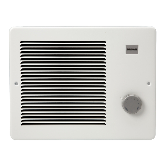
Yes, the Broan wall heater model 174 has an easily accessible, front-mounted, and adjustable thermostat that allows control of the heater's output.
This answer is automatically generated