Advertisement
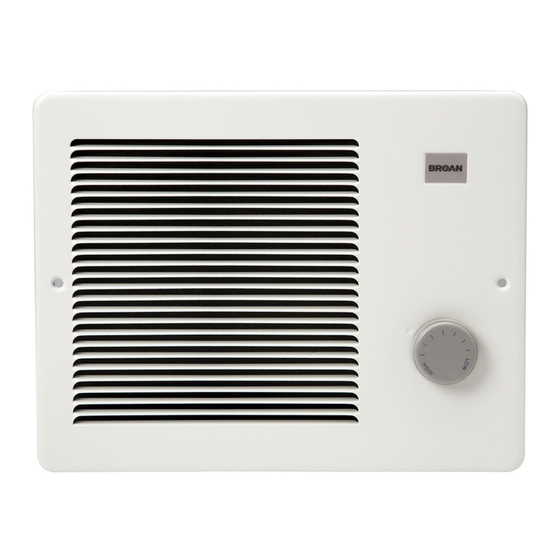
MODELS 170F, 174F & 178F
FAN FORCED WALL HEATERS
FINISH ASSEMBLIES
FOR USE WITH BROAN MODEL 171H ROUGH-IN HOUSING
READ AND SAVE THESE INSTRUCTIONS
WARNING
1. ALL ELECTRICAL WORK MUST BE DONE IN ACCOR-
DANCE WITH LOCAL OR NATIONAL ELECTRICAL CODE
AS APPLICABLE. FOR SAFETY, THIS PRODUCT MUST
BE GROUNDED. IF YOU ARE UNFAMILIAR WITH METH-
ODS OF INSTALLING ELECTRICAL WIRING, SECURE
THE SERVICES OF A QUALIFIED ELECTRICIAN.
2. WHEN WIRING, SERVICING OR CLEANING THIS UNIT,
TURN OFF POWER AND LOCK OUT SERVICE PANEL.
FAILURE TO DO SO COULD ALLOW OTHERS OR THER-
MOSTAT TO TURN ON POWER UNEXPECTEDLY WHICH
MAY CAUSE FATAL ELECTRICAL SHOCK.
3. To avoid electrical shock:
• DO NOT install unit in a tub or shower enclosure or any
location where it may come in contact with water.
• NEVER place a switch where it can be reached from a
tub or shower.
4. DO NOT install this unit in an area where chemicals or
other flammables are stored or used. Explosion and fire
may result
.
PLAN THE INSTALLATION
This wall heater finish assembly is intended for installation
into a Broan Model 171H rough-in housing — after the wall
has been completed.
The heater can be operated using the Broan Model 86 Line-
Voltage Thermostat from a wall location or the Broan Model
83 Integral Thermostat installed into heater. Purchase the con-
trol separately.
The table below lists the ratings for each model.
MODELS
VOLTS
AMPS
120
8.33/4.16
170F
240
4.16
208
3.61
120
12.5/6.25
174F
240
6.25
208
5.41
178F
240
8.33/4.16
208
7.21/3.61
BOLD ratings are factory wired. See "OPTIONAL WIRING
CONVERSIONS" section on pages 2 and 3 for wattage and
voltage conversion instructions.
WATTS
BTU/HR
1000/500
3413/1707
1000
3413
750
2560
1500/750
5120/2560
1500
5120
1125
3640
2000/1000
6827/3413
1500/750
5120/2560
!
CAUTION
1. This product may ONLY be installed horizontally in a wall.
DO NOT MOUNT IN ANY OTHER POSITION.
2. Install heater at least 6" from floor or any adjacent vertical
surface.
3. DO NOT locate heater behind a door, furniture, drapes,
etc., where the air flow to the unit would be restricted.
4. Provide heater with an appropriately-rated electrical cir-
cuit to prevent tripped breakers or blown fuses. (See chart
below).
5. DO NOT CONNECT HEATER TO DIMMER SWITCH OR
SPEED CONTROL.
6. To avoid motor bearing damage and noisy and/or unbal-
anced impellers, keep drywall spray, construction dust,
etc., off power unit.
7. Please read specification label on product for further infor-
mation and requirements.
Follow these basic steps when installing this heater:
• Remove the housing mask.
• Fasten finish assembly inside housing.
• Plug assembly in.
• Attach grille.
DRYWALL
GRILLE
WALL
STUD
HEATER
HOUSING
POWER
CABLE
Advertisement
Table of Contents

Related Manuals for Broan 170F


Summary of Contents for Broan 170F
- Page 1 PLAN THE INSTALLATION This wall heater finish assembly is intended for installation into a Broan Model 171H rough-in housing — after the wall has been completed. The heater can be operated using the Broan Model 86 Line- Voltage Thermostat from a wall location or the Broan Model 83 Integral Thermostat installed into heater.
-
Page 2: Wiring Diagram
Disconnect ONE of the black wires with an insulated termi- nal from the motor. 2. 120 VAC to 240 VAC Conversion. (Factory-wired 120 VAC Models 170F and 174F ONLY) 1) Disconnect ONE of the black wires with an insulated terminal from the motor. - Page 3 IMPLIED, INCLUDING, BUT NOT LIMITED TO, IMPLIED WARRANTIES OF MERCHANTABILITY OR FITNESS FOR A PARTICULAR PURPOSE. During this one-year period, Broan-NuTone LLC will, at its option, repair or replace, without charge, any product or part which is found to be defective under normal use and service.
-
Page 4: Service Parts
Heating Element (Model 178F) 93270619 Wire Clamp 97008682 Partition Plate Assembly Always order replacement parts by part number - NOT key number. Broan-NuTone LLC, 926 West State Street, Hartford, WI 53027 PART NUMBER DESCRIPTION 99260428 Nut, #6-32 x 5/16 Keps (2 Required)
Need help?
Do you have a question about the 170F and is the answer not in the manual?
Questions and answers