Table of Contents
Advertisement
Quick Links
Advertisement
Table of Contents

Subscribe to Our Youtube Channel
Related Manuals for ASTRO U 261


Summary of Contents for ASTRO U 261
- Page 1 User Guide U 261 IP / ASI Gateway...
- Page 2 Olefant 1-3 D-51427 Bergisch Gladbach (Germany) Tel.: (+49) 2204 405-0 All other parts of the software of this product is Copyright by Astro Strobel Kommunika- tionssysteme GmbH Pictograms and safety instructions Pictograms are graphical symbols with a defined meaning. You will find the following...
-
Page 3: Table Of Contents
2.3 Equipotential bonding/grounding..............5 2.4 Servicing and repair ..................6 2.5 Technical data on the power supply..............6 General introduction......................7 3.1 Connecting the U 261 to a PC/Laptop .............7 3.2 The web browser user interface...............7 Login..........................8 Settings ..........................9 5.1 Setting the IP interfaces...................9 5.2 Setting the IP Management interfaces..............10... -
Page 4: Illustrations
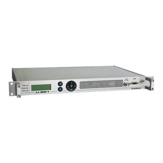
1 Illustrations Power LED BNC ASI input Warning LED Failure LED Display of Management BNC ASI outputs IP addresses MAC address sticker Mains supply Data ports Grounding connection Management ports User Guide U 261... -
Page 5: Introduction
The device must be opened only by authorized specialist personnel inspected by the Chamber of Industry and Commerce. The device must be repaired only by authorized specialist personnel inspected by the Chamber of Industry and Commerce, or by sending it to ASTRO with the preci- se description of the fault. -
Page 6: Servicing And Repair
0,19 – 0,34 A per power supply unit Degree of protection according to EN 60529: IP 20 Max. device ambient temperature: 45°C Mains fuses: T2A L 250V The U 261 must be operated only with the original power supply unit! User Guide U 261... -
Page 7: General Introduction
If the device is connected to a PC / laptop by means of one of the network ports and once the PC/laptop has been appropriately configured by means of the network settings, configuration of the U 261 can be started following input of the IP address in the address line of the Web browser. 3.2 The web browser user interface The web browser user interface is split into a topframe, leftframe and mainframe. -
Page 8: Login
Figure 2: View of U 261 display and LEDs in the Web browser user interface In the example for figure 2, the device is reporting the error "IP RX4A Data Loss", and precisely this error message can also be seen in the display of the U 261. -
Page 9: Settings
This allows unauthorized access to be prevented. Only one user/BC 4 can ever be logged in on the U 261 Gateway. The very bottom of the leftframe of the Web browser user interface shows which user is currently logged in. -
Page 10: Setting The Ip Management Interfaces
Figure 6: Detail from the basic settings of the U 261 "Save, Load, Default & Reboot" "Default" is used to restore the factory settings, and "Reboot" prompts the advice to restart with the operating parameters saved in the flash memory. -
Page 11: Test Generator
The generated data stream comprises zero packets with a length of 188 and can be configured in a range from 1 - 197 Mbps. If the system contains several U 261 Gateways, a packet ID can be allocated to distinguish the test signals. -
Page 12: Ip Setting For Transmission And Reception Mode
Clicking on the "IP TX & IP RX" submenu takes you to the settings for the transmission and recep- tion modes of the U 261. This page provides an overview of the transmission port (IP TX) of the U 261, the general settings of the reception ports (IP RX Common Settings) and the detailed set- tings of the reception ports (IP RX Channel Settings). -
Page 13: Ip Setting For Transmission Port
IP. Usually, a multicast address is input here, since this allows the data stream to be received by several U 261 Gateways. By contrast, a unicast address can be received only by one U 261 Gateway. -
Page 14: Destination Mac
9.5 VLAN Tags If the U 261 Gateway is intended to cover various VLANs, it is possible for the data packets to be assigned different VLAN tags. This ensures that data packets are routed only to the desired VLANs, or each VLAN receives only the data packets which are intended for it. -
Page 15: Ip Setting For Reception Ports
Figure 14: Setting details for the reception port The "Receive IP:Port" line is used to input the IP address and the UDP port at which the U 261 Gateway needs to receive the data stream. User Guide U 261... - Page 16 A data stream can arrive with a CBR (Constant Bit Ratio) in the U 261 Gateway, or with a VBR (Variable Bit Ratio). In any case, CBR is used for MPTSs (Multiple Program Transport Stream) but also for SPTSs (Single Program Transport Stream).
-
Page 17: Configuring The Output Multiplexer
The "Output Mux Settings" are used to assign an IP RX port to each ASI output of the U 261 Gate- way. An IP RX port can also be routed to several ASI outputs, so that the U 261 can also be used as an ASI distributor. -
Page 18: User Administration
This makes it possible to avoid confusing appliances and locations when configuring remotely. 13 Transport Stream Analysis By purchasing a license, the U 261 can be equipped with a transport stream analyzer. This ana- lyzer shows the structure of the MPEG2 TS from the tables to the individual PID and its service. - Page 19 Wait until the "...done!" message appears. Clicking on the "+" or "-" symbols displays or hides the details. Through selection of the "ASI TP" as the TS to be analyzed, the TS analyzer also provides the option of analyzing externally applied ASI signals. User Guide U 261...
-
Page 20: Licensing
"Copy/Paste", and clicking on the "Submit" button transfers the license to the U 261 Gateway. If the license is valid, this is confirmed by a message. An inva- lid license is indicated by an error message. -
Page 21: Update Using The Example Of A Tftp Server For Windows
15.2 Update using the example of a TFTP Server for Windows Should there be no firm (T)FTP server set up for updating the U 261 Gateway, it is also possible to transfer locally stored update files to the Gateway. For this, it is recommended that a TFTP pro- gram be used. - Page 22 The "tftpd32" program is started directly from the folder with the U 261 update files. In the window that opens, click on the "Settings" button first and make the settings as shown in Figure 21: Figure 21: Settings for the tftpd32 TFTP program To start the update, the server address which is input into the "(T)FTP Server address"...
-
Page 23: Log Book
16 Log Book Clicking on the "System Log" submenu takes you to the U 261 Gateway's log book. This docu- ments all processes which are relevant to operation. Figure 22: Example view of the U 261 log book The processes are sorted according to the time of occurrence. The logfile is erased by checking "Check box to clear log on refresh"... -
Page 24: Statistics
17 Statistics Clicking on the "Statistics" submenu takes you to the statistics relating to the data transfer of the U 261 Gateway. This displays all statistics which are relevant to operation and which can be used for analysis. Figure 24: Statistics for U 261 data transfer... -
Page 25: Network Properties
The network properties can be displayed by clicking on the "Network" submenu. The displayed characteristics are purely informative and serve to describe the network. Figure 25: Example view of the network properties in the "Network" submenu User Guide U 261... -
Page 26: Logout
If you confirm the question using the "Yes" button, you are logged out. It is not possible to make any further settings without logging in again, but it is possible to view the U 261 Gateway's set- tings. The setting items are inactive, however. -
Page 27: Technical Data
Input voltage [VDC] 230 V -48 V Abmessungen / Dimensions 1 HE / 19" / 1 RU / 19" zulässige Umgebungstemperatur [°C] 0 … + 50 Temperature range Technical improvements, changes to the design and errors excepted. User Guide U 261... - Page 28 ASTRO Strobel Kommunikationssysteme GmbH Olefant 1–3, D-51427 Bergisch Gladbach (Bensberg) Tel.: 0 22 04 / 4 05-0, Fax: 0 22 04 / 4 05-10 eMail: kontakt@astro-kom.de, www.astro-kom.de...
Need help?
Do you have a question about the U 261 and is the answer not in the manual?
Questions and answers