
Related Manuals for Siemens SIMOTICS DC 1GH7


Summary of Contents for Siemens SIMOTICS DC 1GH7
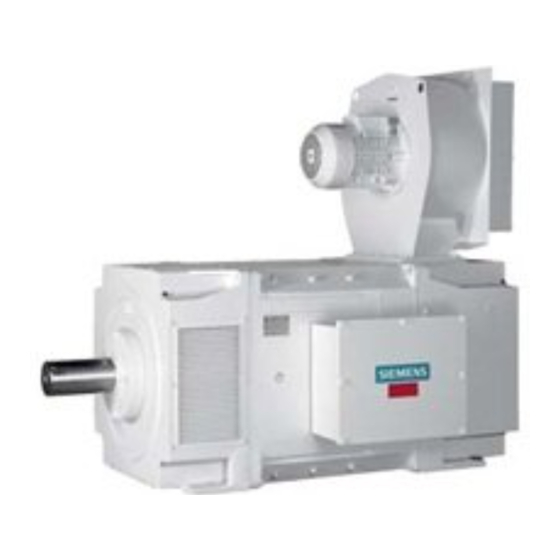
- Page 1 SIMOTICS DC DC motor Type 1GH7 Operating Instructions / Installation Instructions Edition 02/2016 Answers for industry.
- Page 2 08.02.2016 10:34 V4.00...
- Page 3 Introduction Safety notes Description SIMOTICS DC Preparations for use DC motor 1GH7 Assembling Electrical connection Operating Instructions Installation Instructions Commissioning Operation Maintenance Spare Parts Disposal Service and Support Technical data and drawings Quality documents Checklists Edition 02/2016...
- Page 4 Note the following: WARNING Siemens products may only be used for the applications described in the catalog and in the relevant technical documentation. If products and components from other manufacturers are used, these must be recommended or approved by Siemens. Proper transport, storage, installation, assembly, commissioning, operation and maintenance are required to ensure that the products operate safely and without any problems.
-
Page 5: Table Of Contents
4.7.7 Lifting and transporting the machine..................28 4.7.8 Storage...........................30 4.7.9 Protection against corrosion....................32 Assembling..............................33 Preparations for installation....................33 5.1.1 Requirements for installation....................33 5.1.2 Insulation resistance and polarization index................34 5.1.3 Testing the insulation resistance and polarization index............34 SIMOTICS DC 1GH7 Operating Instructions 02/2016... - Page 6 Connecting temperature monitoring for the stator winding............57 6.10 Completing connection work....................58 Commissioning............................59 Preparing for commissioning....................59 Measure the insulation resistance before commissioning............60 Greasing the roller bearings prior to commissioning..............60 Minimum radial forces for cylindrical roller bearings..............61 Switch on..........................62 Overspeed..........................63 Switch off..........................63 SIMOTICS DC 1GH7 Operating Instructions 02/2016...
- Page 7 Mounting the rolling-contact bearings..................92 9.2.6 Replacing the speed encoder....................93 9.2.6.1 Speed sensor with conical hub....................93 9.2.6.2 Speed sensor for overhung mounting..................94 9.2.6.3 Speed sensor for construction type IM B5................96 Spare Parts..............................99 10.1 Ordering data.........................99 SIMOTICS DC 1GH7 Operating Instructions 02/2016...
- Page 8 Tightening torques for screw and bolt connections..............117 Quality documents............................119 Checklists..............................121 Switching on.........................122 Commissioning........................123 Inspection at standstill......................124 Inspection when the motor is running..................125 Index.................................127 Tables Table 3-1 Insulation classes........................20 Table 3-2 Machine design ..........................20 Table 3-3 Data on the rating plate......................21 SIMOTICS DC 1GH7 Operating Instructions 02/2016...
- Page 9 Items to check during commissioning..................123 Table D-3 Items to inspect when machine is at standstill................124 Table D-4 Items to inspect when the motor is running................125 Images Image 3-1 Block diagram of motor type 1GH....................19 SIMOTICS DC 1GH7 Operating Instructions 02/2016...
- Page 10 Speed sensor with conical hub for shaft heights 180 to 630.............109 Image 10-10 Speed sensor for overhung mounting for shaft heights 180 to 630..........110 Image 10-11 Speed sensor for construction type IM B5 for shaft heights 180 to 630........111 SIMOTICS DC 1GH7 Operating Instructions 02/2016...
-
Page 11: Introduction
– Lists on the second level are hyphenated. Note A Note is an important item of information about the product, handling of the product or the relevant section of the document. Notes provide you with help or further suggestions/ideas. SIMOTICS DC 1GH7 Operating Instructions 02/2016... - Page 12 Introduction 1.1 About these instructions SIMOTICS DC 1GH7 Operating Instructions 02/2016...
-
Page 13: Safety Notes
EN 50110‑1 "Working in a voltage-free state". Apply the five safety rules in the sequence stated before starting work. Five safety rules 1. Disconnect the system. Also disconnect the auxiliary circuits, for example, anti-condensation heating. 2. Secure against reconnection. 3. Verify absence of operating voltage. SIMOTICS DC 1GH7 Operating Instructions 02/2016... -
Page 14: Qualified Personnel
● Always observe the “five safety rules" (Page 13) when carrying out any work on the machine. ● Only remove the covers using the methods described by these operating instructions. ● Operate the machine properly. ● Regularly and correctly maintain the machine. SIMOTICS DC 1GH7 Operating Instructions 02/2016... - Page 15 Burns and other damage to health and material may result. ● Read the information in these operating instructions and the product information supplied by the manufacturer. ● Observe the relevant safety regulations and wear the personal protective equipment specified. SIMOTICS DC 1GH7 Operating Instructions 02/2016...
-
Page 16: Electrostatic Sensitive Devices
● Always place electrostatic sensitive devices on conductive bases. ● Always pack, store and transport electronic modules or components in conductive packaging, such as: – Metallized plastic or metal containers – Conductive foam material – Domestic aluminum foil SIMOTICS DC 1GH7 Operating Instructions 02/2016... -
Page 17: Electromagnetic Compatibility
A strongly irregular torque, for example with the drive of a reciprocating motor, forces a non- sinusoidal motor current. The emerging harmonics can have an impermissible influence on the line power supply via the connection lines. SIMOTICS DC 1GH7 Operating Instructions 02/2016... -
Page 18: Electromagnetic Fields When Operating Electrical Power Engineering Installations
● Protect the personnel working in the plant by taking appropriate measures, such as erecting identifying markings, safety barriers and warning signs and giving safety talks. ● Observe the nationally applicable health and safety regulations. ● Do not carry any magnetic or electronic data media. SIMOTICS DC 1GH7 Operating Instructions 02/2016... -
Page 19: Description
The forced-ventilated machine is open-circuit-ventilated with cooling method IC 17, with pipe connections on both sides with cooling method IC 37. The external fan is connected to the machine via a pipe. The fan and cooling pipe are not included in the scope of supply. SIMOTICS DC 1GH7 Operating Instructions 02/2016... -
Page 20: Table 3-1 Insulation Classes
Please refer to the EC or EU Declaration of Conformity for the versions of the harmonized standards referenced. Table 3-2 Machine design Characteristic Standard Ratings and operating performance IEC/EN 60034‑1 Degree of protection IEC/EN 60034‑5 SIMOTICS DC 1GH7 Operating Instructions 02/2016... -
Page 21: Table 3-3 Data On The Rating Plate
⑫ Armature voltage [V] Standards and regulations ⑤ ⑬ Armature current [A] Motor weight [t] ⑥ ⑭ Exciter data Power [kW] ⑦ ⑮ Cooling method Speed [RPM] ⑧ ⑯ Brush equipment Air flow direction SIMOTICS DC 1GH7 Operating Instructions 02/2016... - Page 22 The rolling-contact bearing is normally a floating bearing at the drive end and a locating bearing at the non-drive end. You will find further information in section "Spare parts (Page 99)." On machines with a regreasing device, the lubricant plate specifies the types of rolling-contact bearing fitted. SIMOTICS DC 1GH7 Operating Instructions 02/2016...
-
Page 23: Preparations For Use
Take steps to reduce noise, such as introducing covers and protective insulation or adopting hearing protection measures, so that the machine can be operated safely within your system. SIMOTICS DC 1GH7 Operating Instructions 02/2016... -
Page 24: Ensuring Cooling
This can result in death, serious injury or material damage. When planning the system, make due allowance for the maximum air gap torques that can occur. Note The system planner is responsible for the entire drive train. SIMOTICS DC 1GH7 Operating Instructions 02/2016... -
Page 25: Transport And Storage
● On machines that have been supplied with a rotor shipping brace, secure the rotor as per the notes on transportation. ● Protect the machine against strong radial vibrations, since the rotor shipping brace might not absorb these completely. SIMOTICS DC 1GH7 Operating Instructions 02/2016... -
Page 26: Checking The Load Handling Attachments
● When lifting the machine, use only approved and undamaged sling guides and spreaders of sufficient rated capacity. Check the lifting equipment prior to its use. The weight of the machine is shown on the rating plate. SIMOTICS DC 1GH7 Operating Instructions 02/2016... - Page 27 ● Always take account of the center of gravity when transporting or lifting the motor. If the center of gravity is not located centrally between the attachment points, then position the hoisting hook above the center of gravity. SIMOTICS DC 1GH7 Operating Instructions 02/2016...
-
Page 28: Transporting The Machine Set
① ③ Sleeve Fixture ② ④ Coupling Shaft screw Image 4-1 Rotor shipping brace without coupling (1) and with coupling (2). SIMOTICS DC 1GH7 Operating Instructions 02/2016... - Page 29 If the lifting gear or load handling attachments were to fail, the machine could fall. This can result in death, serious injury or material damage. Never remain under or in the immediate vicinity of the machine when it is raised. SIMOTICS DC 1GH7 Operating Instructions 02/2016...
-
Page 30: Storage
● Ensure that the air circulation under the equipment is not impeded. – Place wooden spacer blocks between the covers and the motor. – Covers or tarpaulins must not trail on the floor around the machine. SIMOTICS DC 1GH7 Operating Instructions 02/2016... - Page 31 (if available), and ensure that the air circulates in the storage room. Storage for longer than three months Lubricate the machine after every two years of storage. 1. Unpack the machine. 2. Remove the rotor shipping brace, if one is being used. SIMOTICS DC 1GH7 Operating Instructions 02/2016...
-
Page 32: Protection Against Corrosion
● Inspect the machine regularly and apply an additional coating of corrosion protection if necessary. Document all preservation measures taken so that they can be reversed before the machines are put back into service. SIMOTICS DC 1GH7 Operating Instructions 02/2016... -
Page 33: Assembling
In the delivery state, the machine corresponds to the requirements of the European directives. Unauthorized changes or modifications to the machine lead to the loss of conformity with European directives and the loss of warranty. SIMOTICS DC 1GH7 Operating Instructions 02/2016... -
Page 34: Insulation Resistance And Polarization Index
Measure the insulation resistance 1. Before you begin measuring the insulation resistance, please read the operating manual for the insulation resistance meter you are going to use. 2. Make sure that no power cables are connected. SIMOTICS DC 1GH7 Operating Instructions 02/2016... - Page 35 In this case, doubling or halving the insulation resistance at a temperature change of 10 K is used as the basis. ● The insulation resistance halves every time the temperature rises by 10 K. ● The resistance doubles every time the temperature falls by 10 K. SIMOTICS DC 1GH7 Operating Instructions 02/2016...
- Page 36 Limit values of the anti-condensation heating insulation resistance The insulation resistance of the anti-condensation heating with respect to the machine housing should not be lower than 1 MΩ when measured at 500 V DC. SIMOTICS DC 1GH7 Operating Instructions 02/2016...
-
Page 37: Preparing The Mating Faces
● Measuring the concentricity and axial eccentricity tolerances ● Positioning the machine If you are not familiar with the prescribed measures and procedures, then you can make use of the services offered by the local Service Center (Page 115). SIMOTICS DC 1GH7 Operating Instructions 02/2016... -
Page 38: Checking The Load Handling Attachments
Failure to fit the rotor shipping brace can result in damage to the bearings while the machine is being turned onto its side. Fix the rotor in place before you turn the machine into a horizontal position. SIMOTICS DC 1GH7 Operating Instructions 02/2016... -
Page 39: Removing Anti-Corrosion Protection
If you use metal objects such as scrapers, spatulas, or plates to remove the anti-corrosion protection, this could result in damage to the surfaces of the machine parts. ● Lightly oil the depreserved surfaces. SIMOTICS DC 1GH7 Operating Instructions 02/2016... -
Page 40: Mounting The Output Elements
The transmission element must be pulled on in one continuous operation via the front thread holes in the shaft or pushed on by hand. – Do not strike it with a hammer, as this would damage the bearings. SIMOTICS DC 1GH7 Operating Instructions 02/2016... -
Page 41: Lifting And Transporting The Machine
– Do not exceed the maximum lifting acceleration and lifting speed specified on the lifting plate. Lift the machine without jerking it. Acceleration a ≤ 0.4 g (≈ 4 m/s Velocity v ≤ 20 m/min ● Use only the load carrying device on the stator frame for lifting. SIMOTICS DC 1GH7 Operating Instructions 02/2016... - Page 42 If the lifting gear or load handling attachments were to fail, the machine could fall. This can result in death, serious injury or material damage. Never remain under or in the immediate vicinity of the machine when it is raised. SIMOTICS DC 1GH7 Operating Instructions 02/2016...
-
Page 43: Putting The Machine Down
The transmission element such as a coupling half has already been pulled on. Roughly aligning the machine ● For horizontal positioning, push the motor sideways across the foundation. When doing so, ensure that the axial position is maintained. SIMOTICS DC 1GH7 Operating Instructions 02/2016... -
Page 44: Installing The Machine
Installing the machine Note Service Center For any installation work that is required, contact the Service Center (Page 115) or commission service engineers trained by Siemens and authorized for this task. 5.3.1 Safety instructions for installation WARNING Inappropriate fastening material If screws of an incorrect property class have been selected or if they have been fastened to an incorrect tightening torque, they may break or become loose. -
Page 45: Selecting Fixing Screws
The balance state of the shaft (full-key or half-key balancing) and alignment errors primarily influence the service life of the bearing, especially for high motor speeds or when using rigid couplings. SIMOTICS DC 1GH7 Operating Instructions 02/2016... -
Page 46: Schematic Diagram: Aligning The Machine To The Driven Machine
1500 rpm < n ≤ 3600 rpm = 0.05 mm = 0.05 mm / 100 mm ∅ D Note Machine expansion When performing alignment, make allowance for the thermal expansion of the machine due to rising temperature. SIMOTICS DC 1GH7 Operating Instructions 02/2016... -
Page 47: Aligning The Machine To The Driven Machine And Attaching It To It (Flange Mounting, Vertical)
The standard flange is provided with a centering. The choice of fit for the mating flange on the driven machine is the system manufacturer's or the plant operator's responsibility. Note If the machine is not fitted with a standard flange, align the machine to suit the driven machine. SIMOTICS DC 1GH7 Operating Instructions 02/2016... -
Page 48: Mounting The Machine
0.05 mm in diameter. 5.3.8 Axial and radial forces You can obtain the permissible values for axial and radial forces by contacting the Siemens Service Center (Page 115) or referring to the machine catalog. SIMOTICS DC 1GH7 Operating Instructions 02/2016... - Page 49 On machines with a belt pulley, the bearings and shaft can be damaged if the belt tension is too high. It is essential, therefore, that the radial and axial shaft load values are within tolerance. SIMOTICS DC 1GH7 Operating Instructions 02/2016...
- Page 50 Assembling 5.3 Installing the machine SIMOTICS DC 1GH7 Operating Instructions 02/2016...
-
Page 51: Electrical Connection
4. Close unused cable entries with suitable seal inserts. Please ensure the following: – The seals are made of resistant, approved material. – The degree of protection is guaranteed. Use sealing rings or adhesive, if necessary – Only open the cable entries with a tool. SIMOTICS DC 1GH7 Operating Instructions 02/2016... -
Page 52: Terminal Designations
Use the matching cable end pieces. ● Make sure the protective conductor connection is secure. ● Comply with the rating plate data and the terminal diagram in the terminal box when making the electrical connections. SIMOTICS DC 1GH7 Operating Instructions 02/2016... -
Page 53: Connecting The Main Circuit
6 x 240 mm 2 x 35 mm 2 x 70 mm tion Auxiliary terminals Terminal size Tightening torque 4 Nm 1.2 Nm 1.2 Nm Connectable cable cross-sec‐ 35 mm 6 mm 6 mm tion SIMOTICS DC 1GH7 Operating Instructions 02/2016... -
Page 54: Image 6-1 Connection Of Main Terminals With Cable Lug
DIN 128. Connection without cable lugs If terminal box size gk 602 or gk 702 is mounted on the machine, you can also connect the cables without cable lugs. Image 6-3 Connection without cable lugs SIMOTICS DC 1GH7 Operating Instructions 02/2016... -
Page 55: Connecting The Grounding Conductor
Different values apply to cable lugs or grounding terminals. Table 6-3 Tightening torque of screws with cable lugs Bolt Screw-in depth Tightening torque M12 x 25 > 16 mm 38 Nm M16 x 35 > 20 mm 92 Nm SIMOTICS DC 1GH7 Operating Instructions 02/2016... -
Page 56: Internal Equipotential Bonding
When performing any installation work you must always take care to ensure that all equipotential bonding connections remain effective. Connecting the auxiliary circuits Auxiliary circuit Terminal strips for cable cross-sections of up to 2.5 mm are provided for connecting auxiliary circuits, e.g. temperature sensor or anti-condensation heating. SIMOTICS DC 1GH7 Operating Instructions 02/2016... -
Page 57: Connecting Temperature Monitoring For The Stator Winding
. Connecting temperature monitoring for the stator winding The stator winding is monitored for thermal loading by resistance thermometers embedded in the stator winding. SIMOTICS DC 1GH7 Operating Instructions 02/2016... -
Page 58: Completing Connection Work
– With a U-shaped terminal box casing, the entry plate is aligned and secured in such a way that the seat for the box cover seal is continuous all the way round. 2. Then close the terminal box. Tightening torque for the cover fastening screws is 22 Nm. SIMOTICS DC 1GH7 Operating Instructions 02/2016... -
Page 59: Commissioning
– Gear tooth flank play and gear tooth tip play, as well as radial play, are properly adjusted if there is a gearwheel output. ● The minimum insulation resistance values are within tolerance. ● If the bearings are insulated, the insulation has not been bridged. SIMOTICS DC 1GH7 Operating Instructions 02/2016... -
Page 60: Measure The Insulation Resistance Before Commissioning
Detailed information on testing and the limit values can be found here: "Testing the insulation resistance and polarization index" (Page 34) Greasing the roller bearings prior to commissioning The following information assumes that the specified storage conditions have been complied with. SIMOTICS DC 1GH7 Operating Instructions 02/2016... -
Page 61: Minimum Radial Forces For Cylindrical Roller Bearings
Transport and storage (Page 25) Minimum radial forces for cylindrical roller bearings Note Maintaining the minimum radial forces Operating roller bearings without a load can damage them. Maintain the minimum radial forces specified when using cylindrical roller bearings. SIMOTICS DC 1GH7 Operating Instructions 02/2016... -
Page 62: Switch On
● If mechanical operation does not improve immediately after switching the motor off, the cause is mechanical, e.g. imbalance of electrical machines, etc. ● If the motor is running perfectly, switch on the cooling equipment. SIMOTICS DC 1GH7 Operating Instructions 02/2016... -
Page 63: Overspeed
Switch-off is usually initiated and controlled by an automatic control. If the machine is not switched off by a control, proceed as follows: 1. Switch the machine off. 2. Switch off any external fans. SIMOTICS DC 1GH7 Operating Instructions 02/2016... - Page 64 Commissioning 7.7 Switch off 3. Switch off the coolant supply. Follow the operating instructions provided by the manufacturer. 4. Switch on the anti-condensation heating. SIMOTICS DC 1GH7 Operating Instructions 02/2016...
-
Page 65: Operation
This can cause faults which can result in eventual or immediate death, serious injury or material damage. ● Immediately inform the maintenance personnel. ● If you are in doubt, immediately switch off the motor, being sure to observe the system- specific safety conditions. SIMOTICS DC 1GH7 Operating Instructions 02/2016... -
Page 66: Switching On The Machine
The vibration response of the system at the location where it is installed can result in greater vibration magnitudes on the motor. SIMOTICS DC 1GH7 Operating Instructions 02/2016... -
Page 67: Regreasing Roller Bearings
≤ 2,55 If higher levels of vibration than the above specified occur in operation, special measures must be taken. For more information, please contact your local Siemens sales office. Regreasing roller bearings Refer to the regreasing instructions for the roller bearings on the lubricant plate. -
Page 68: Measures In Non-Operational Periods
● If the machine has been non-operational for longer than a year, regrease the bearings before commissioning. Turn the shaft to distribute the grease in the bearings. ● Pay attention to the instructions on the lubricant plate. SIMOTICS DC 1GH7 Operating Instructions 02/2016... -
Page 69: Avoidance Of Damage To Roller Bearings During Stoppages
● Can the machine be put into operation? ● Must the windings be cleaned or dried? Detailed information on testing and the limit values can be found here: "Testing the insulation resistance and polarization index" (Page 34) SIMOTICS DC 1GH7 Operating Instructions 02/2016... -
Page 70: Decommissioning The Machine
Loading at standstill Load stationary DC motors with armature current only for short periods so as to protect the commutator against damage. Obtain the permissible current and time values for loading at standstill from the manufacturer. SIMOTICS DC 1GH7 Operating Instructions 02/2016... -
Page 71: Faults
Immediately perform an inspection after such faults. Correct the cause of the fault as described in the respective remedial measures section. Repair any damage to the machine. SIMOTICS DC 1GH7 Operating Instructions 02/2016... -
Page 72: Faults In Operation
Cooling fault Cooling air-flow rate too low (commutator temper‐ Improve ventilation circuit ature too high) Component defect Interturn fault Repair winding Out-of-round commutator Rework commutator Rotor imbalance Balance rotor Bearing damage Repair or replace bearing SIMOTICS DC 1GH7 Operating Instructions 02/2016... -
Page 73: Roller Bearing Faults
Too much grease in bearing Remove surplus grease. Wrong grease in the bearing Use the correct grease. Friction marks on raceway Replace the bearing. Scoring (brinelling) Replace the bearing. Avoid any vibration at standstill SIMOTICS DC 1GH7 Operating Instructions 02/2016... -
Page 74: Brush Faults
Cooling-air flow rate too low (commutator tempera‐ Improve cooling ture too high) Brush fault Incorrect or unsuitable brush material Change brush material Component defect Out-of-round commutator Overrev commutator Protruding segment insulation Pocket mill segment insulation Rotor imbalance Balance rotor SIMOTICS DC 1GH7 Operating Instructions 02/2016... -
Page 75: Commutator Faults
Brushes not in neutral zone Correct setting Component defect Interruption in armature winding Repair winding Faulty solder joint Resolder solder joint Out-of-round commutator Rework commutator Conductive inclusions in segment slots Pocket mill segment insulation SIMOTICS DC 1GH7 Operating Instructions 02/2016... - Page 76 Operation 8.9 Faults SIMOTICS DC 1GH7 Operating Instructions 02/2016...
-
Page 77: Maintenance
Machine damage If the machine is not maintained it can suffer damage. This can cause faults which can result in eventual or immediate death, serious injury or material damage. Perform regular maintenance on the machine. SIMOTICS DC 1GH7 Operating Instructions 02/2016... -
Page 78: Initial Inspection
● Perform the initial inspection after installing or commissioning the motor. Normally the initial inspection is only necessary after approx. 500 hours of operation. ● Perform follow-up inspections after every approx. 2,000 hours of operation. SIMOTICS DC 1GH7 Operating Instructions 02/2016... - Page 79 The brush height must be reduced to below the minimum. ● Any defects discovered during checking should be fully corrected. Note The inspection measures may be required depending on the plant specification and operating conditions. See also Inspection at standstill (Page 124) SIMOTICS DC 1GH7 Operating Instructions 02/2016...
-
Page 80: Mttr
● The relevant technical data are observed: power consumption, temperature of windings, bearings, coolants, etc. ● There should be no oil, grease, or water leakages. ● The smooth running characteristics and motor running noise have not deteriorated. ● No impermissible brush sparking occurs in operation. SIMOTICS DC 1GH7 Operating Instructions 02/2016... -
Page 81: Regreasing Rolling-Contact Bearings
The rotor can fall out when work is being carried out on the locating bearing and the motor is vertical. This can result in death, serious injury or material damage. Support or relieve the rotor of any load when work is being carried out with the machine in a vertical position. SIMOTICS DC 1GH7 Operating Instructions 02/2016... -
Page 82: Regreasing Intervals And Grease Types
Special types of grease are used on machines that are designed for use at temperatures below -20 °C. These grease types are specified on the lubricant plate. Other types of grease are not permitted. SIMOTICS DC 1GH7 Operating Instructions 02/2016... -
Page 83: Clean The Machine
In normal operation, check regularly to ensure the carbon brushes are in good contact with the commutator and are moving freely in the brush guides. Brush height The wear limit of carbon brushes is indicated by a line or by the lower edge of the manufacturer's name stamp. SIMOTICS DC 1GH7 Operating Instructions 02/2016... -
Page 84: Replacing The Carbon Brushes
Avoid damaging the brush edges when grinding in the new carbon brushes. 6. Carefully remove the emery cloth and any adhesive-tape residue left behind on the commutator surface. SIMOTICS DC 1GH7 Operating Instructions 02/2016... -
Page 85: Setting The Brush Rocker And Brush Holder
● Clean the slots between the commutator segments with a suitable wooden slat or glass pencil. Note Sparking or flashover caused by unclean slots Dirty slots can cause sparking or flashovers on the commutator. SIMOTICS DC 1GH7 Operating Instructions 02/2016... - Page 86 (d ) given in the following table. Table 9-3 Commutator overhaul – minimum permissible diameter Shaft height Nominal diameter d (mm) Minimum diameter d (mm) 1G.5 / 1H.5 1G.6 / 1H.6 1G.7 / 1H.7 SIMOTICS DC 1GH7 Operating Instructions 02/2016...
-
Page 87: Maintaining Terminal Boxes
● Terminal boxes must be regularly checked for tightness, undamaged insulation, and tight terminal connections. ● If dust or humidity have infiltrated the terminal box, this should be cleaned and dried (particularly the insulators). SIMOTICS DC 1GH7 Operating Instructions 02/2016... -
Page 88: Touch Up Any Damaged Paintwork
(Page 13) and the specifications contained in EN 50110‑1 regarding safe operation of electrical equipment. Note If the motor has to be transported, please observe the information and instructions in the "Transport" (Page 25) section. SIMOTICS DC 1GH7 Operating Instructions 02/2016... -
Page 89: Prepare Servicing Work
If the motor is in a vertical position, the rotor can fall out while work is being performed on the locating bearing. This can result in death, serious injury or damage. ● Support or unload the rotor when carrying out work with the machine in a vertical position. SIMOTICS DC 1GH7 Operating Instructions 02/2016... -
Page 90: Disassembling The Machine
3. Ensure correct assignment and orientation of the parts: bearings, sealing rings, compression springs, spring washers, covers with different centering lengths. 4. When removing the DE bearing shield, make sure that the windings that project from the stator frame do not become damaged. SIMOTICS DC 1GH7 Operating Instructions 02/2016... -
Page 91: Removing Rolling-Contact Bearings
For example, use split rings, spring washers, or LOCTITE. The clamping length is taken as the distance between the head of the bolt and the point at which the bolt is screwed in. SIMOTICS DC 1GH7 Operating Instructions 02/2016... -
Page 92: Mounting The Rolling-Contact Bearings
Speed sensor ● If you are using a speed sensor with an inner V-ring on the outer bearing cover, the V-ring must be positioned against the shoulder of the shaft journal. SIMOTICS DC 1GH7 Operating Instructions 02/2016... -
Page 93: Replacing The Speed Encoder
Recommended torques for tightening the shaft journal Thread size Torque [Nm] Assembly Reinstall the disassembled speed sensor and secure it in position. The legend numbers in the following illustration are explained in chapter Spare parts / Speed sensor (Page 109). SIMOTICS DC 1GH7 Operating Instructions 02/2016... -
Page 94: Speed Sensor For Overhung Mounting
1. Unscrew the speed-sensor stator and move it away, axially. 2. Remove the speed-sensor rotor. To do this, release the lateral set screw in the shaft journal and pull the rotor out, axially. SIMOTICS DC 1GH7 Operating Instructions 02/2016... -
Page 95: Speed Sensor Assembly
● Push the cylindrical shaft extension of the speed-sensor rotor as far as possible into the shaft journal and secure it with the lateral set screw (M4 x 6). ● Use removable LOCTITE and a tightening torque of 13 Nm to attach the set screw. SIMOTICS DC 1GH7 Operating Instructions 02/2016... -
Page 96: Speed Sensor For Construction Type Im B5
Firmly reattach the speed encoder that was removed. If a different design is used, the installation and operating instructions of the speed encoder manufacturer apply. The legend numbers in the following illustration are explained in chapter Spare parts / Speed encoder (Page 109). SIMOTICS DC 1GH7 Operating Instructions 02/2016... -
Page 97: Image 9-6 Speed Encoder Mounting
Thread size Tightening torque [Nm] 1. Check the elastic connecting link (coupling star) to ensure that it is in a good condition and in the correct mounting position. 2. Mount the complete speed encoder. SIMOTICS DC 1GH7 Operating Instructions 02/2016... - Page 98 Maintenance 9.2 Repair SIMOTICS DC 1GH7 Operating Instructions 02/2016...
-
Page 99: Spare Parts
Example ● Terminal box type ● Terminal box cover (part 20.30 ) ● Serial number of the motor ● Machine type SIMOTICS DC 1GH7 Operating Instructions 02/2016... -
Page 100: Ordering Spare Parts Via The Internet
You can use "Spares on Web" to determine the order numbers for motor spare parts quickly and easily. A short description of how to use "Spares on Web" is available on the Internet. Guide for Spares on Web (http://support.automation.siemens.com/WW/news/en/25248626). 10.3 Using commercially available spare parts You can use commercially available, standard components, but ensure that they have the same construction type, dimensions, strength class etc. -
Page 101: Stator And Rotor
Spare parts stator and rotor 1G.7, 1H.7, shaft heights 355 to 450 Designation Designation 3.00 Rolling-contact bearing bush (locating 8.60 Commutator bearing) 4.00 Rolling-contact bearing bush (floating 10.02 Stator frame with main and commutating coil resistors bearing) 5.00 Bearing shield, drive end 10.16 Grounding connection SIMOTICS DC 1GH7 Operating Instructions 02/2016... -
Page 102: Rolling-Contact Bearing
Rolling-contact bearing for 1H.7, 1G.7 Table 10-2 Spare parts rolling-contact bearing for 1H.7, 1G.7 Designation 4.10 Greasing device 4.23 Outer bearing cover with shorter centering recess for floating bearing 4.35 Grease slinger 4.41.1 Deep-groove ball bearing (floating bearing) SIMOTICS DC 1GH7 Operating Instructions 02/2016... - Page 103 Spare Parts 10.5 Rolling-contact bearing Designation 4.45 Compression springs 4.60 Inner bearing cover with felt rings 4.80 Grease nipple SIMOTICS DC 1GH7 Operating Instructions 02/2016...
-
Page 104: Rolling-Contact Bearing For 1G.7, 1H.7, Shaft Heights 355 To 450 With One Shaft Extension, Non-Drive End
Designation 3.21 Outer bearing cover (end cover) 3.30 Locking ring 3.35 Grease slinger 3.40.1 Deep-groove ball bearing (deep-groove ball bearing with sideplate, locating bearing) 3.60 Inner bearing cover with felt rings 3.80 Grease nipple SIMOTICS DC 1GH7 Operating Instructions 02/2016... -
Page 105: Rolling-Contact Bearing For 1G.7, 1H.7, Shaft Heights 355 To 450 With Two Shaft Extensions, Non-Drive End
Spare parts rolling-contact bearing for 1G.7. 1H.7 with two shaft extensions Designation 3.10 Greasing device 3.20 Outer bearing cover 3.30 Locking ring 3.35 Grease slinger 3.40.1 Deep-groove ball bearing (locating bearing) 3.60 Inner bearing cover with felt rings 3.80 Grease nipple SIMOTICS DC 1GH7 Operating Instructions 02/2016... -
Page 106: Rolling-Contact Bearing Seal 1G.6, 1H.6, 1G.7, 1H.7
Spare parts sealing for rolling-contact bearing for 1H.6, 1G.6 Designation 3.10 V ring 4.10 V ring 3.11 Radial shaft sealing ring, for special operating conditions only 4.11 Radial shaft sealing ring, for special operating conditions only SIMOTICS DC 1GH7 Operating Instructions 02/2016... -
Page 107: Terminal Boxes
Image 10-6 Main terminal box 1XB7720 Image 10-7 Cable entry plate 1XB7720 Table 10-6 Spare parts terminal box 1XB7720 Designation 20.20 Terminal box 20.28 Seal 20.30 Cover with seal 20.51 Entry plate with seal SIMOTICS DC 1GH7 Operating Instructions 02/2016... -
Page 108: Auxiliary Terminal Box
Spare Parts 10.6 Terminal boxes 10.6.2 Auxiliary terminal box Image 10-8 Auxiliary terminal box Table 10-7 Spare parts auxiliary terminal box Designation 20.09 Auxiliary terminal box 20.20 Housing 20.83 Rubber sleeve SIMOTICS DC 1GH7 Operating Instructions 02/2016... -
Page 109: Speed Sensor
55.10.1 Speed-sensor rotor 55.10.5 Fastening screw 55.10.8 Carbon brushes 55.20 Bearing covers for speed sensor mounting 55.30 Threaded shaft journal with taper 55.38 V ring See also Speed sensor with conical hub (Page 93) SIMOTICS DC 1GH7 Operating Instructions 02/2016... -
Page 110: Speed Sensor For Overhung Mounting
Speed sensor 55.10.1 Speed-sensor rotor 55.20 Bearing covers for speed sensor mounting 55.31 Threaded shaft journal with cylindrical hole 55.31.5 Locking screw 55.35 Tolerance ring See also Speed sensor for overhung mounting (Page 94) SIMOTICS DC 1GH7 Operating Instructions 02/2016... -
Page 111: Speed Sensor For Construction Type Im B5
Bearing covers for speed sensor mounting 55.35 Tolerance ring 55.42.1 Coupling halves at speed-sensor end for cylindrical speed-sensor shaft 55.42.5 Locking screw 55.44 Coupling star See also Speed sensor for construction type IM B5 (Page 96) SIMOTICS DC 1GH7 Operating Instructions 02/2016... - Page 112 Spare Parts 10.7 Speed sensor SIMOTICS DC 1GH7 Operating Instructions 02/2016...
-
Page 113: Disposal
The machine is made up of heavy parts. These parts are liable to fall during dismantling. This can result in death, serious injury or material damage. Before you release any machine parts, secure them so that they cannot fall. SIMOTICS DC 1GH7 Operating Instructions 02/2016... -
Page 114: Disposal Of Components
● Wooden packaging for sea transport consists of impregnated wood. Observe the local regulations. ● The foil used for water-proof packaging is an aluminum composite foil. It can be recycled thermally. Dirty foil must be disposed of via waste incineration. SIMOTICS DC 1GH7 Operating Instructions 02/2016... -
Page 115: Service And Support
You can find your contact person in the relevant contact database: www.siemens.com/yourcontact (www.siemens.com/yourcontact) SIOS App You can obtain optimum support everywhere using the SIOS App. The SIOS App is available for Apple iOS, Android and Windows phone. SIMOTICS DC 1GH7 Operating Instructions 02/2016... - Page 116 Service and Support SIMOTICS DC 1GH7 Operating Instructions 02/2016...
-
Page 117: Technical Data And Drawings
Table B-1 Tightening torques for screw/bolt connections with a tolerance of ±10% Case 1080 1700 2600 4200 1200 2000 3100 4700 7500 SIMOTICS DC 1GH7 Operating Instructions 02/2016... - Page 118 Note Non-standard tightening torques Different tightening torques for electrical connections and bolted connections for parts with flat seals or insulating parts are specified in the relevant sections and drawings. SIMOTICS DC 1GH7 Operating Instructions 02/2016...
-
Page 119: Quality Documents
Quality documents You can find the quality documents here: https://support.industry.siemens.com/cs/ww/de/ps/13419/cert (https:// support.industry.siemens.com/cs/ww/en/ps/13419/cert) SIMOTICS DC 1GH7 Operating Instructions 02/2016... - Page 120 Quality documents SIMOTICS DC 1GH7 Operating Instructions 02/2016...
-
Page 121: Checklists
Checklists When carrying out any work on the machine, observe the general safety instructions (Page 13) and the specifications contained in EN 50110‑1 regarding safe operation of electrical equipment. SIMOTICS DC 1GH7 Operating Instructions 02/2016... -
Page 122: Switching On
Temperatures of the bearings, windings, etc., monitored and logged until the sys‐ tem reaches a steady state. Operating time reduced accordingly if the water-to-water cooler (if installed) is not operated at this "preliminary" dry run stage. Note: Date Name Signature SIMOTICS DC 1GH7 Operating Instructions 02/2016... -
Page 123: Commissioning
If an air-to-water heat exchanger is installed, the water cooler is connected, filled, air bled, and ready to run A test run has been carried out without water cooling where there has been a lengthy time delay between assembly and commissioning Note: Date Name Signature SIMOTICS DC 1GH7 Operating Instructions 02/2016... -
Page 124: Inspection At Standstill
If heat exchanger is installed: filter change or filter cleaning Check bearing seals Operating hours Sealing of machine If heat exchanger is installed: Check heat exchanger seals Next recommended inspection date: Other remarks: Date Name Signature SIMOTICS DC 1GH7 Operating Instructions 02/2016... -
Page 125: Inspection When The Motor Is Running
Bearing-housing vibrations, drive end, axial, radial, horizontal Bearing-housing vibrations, non-drive end, axial, radial, horizontal Smooth running and running noise of machine Commutation behavior (spark note) Next recommended inspection date: Other remarks: Date Name Signature SIMOTICS DC 1GH7 Operating Instructions 02/2016... - Page 126 Checklists D.4 Inspection when the motor is running SIMOTICS DC 1GH7 Operating Instructions 02/2016...
-
Page 127: Index
Emitted interference, 18 Equipotential bonding, 56 Internal, 56 Cable entry, 51 Equipotential bonding connection, 56 Carbon brushes, 83 ESD guidelines, 16 Mounting, 84 Removal, 84 Replacement, 84 Spare parts, 99 Cassette filter, 83 faults, 65 SIMOTICS DC 1GH7 Operating Instructions 02/2016... - Page 128 Lifting, 27, 29, 42 Property class, 45 Local service, 115 Long-term storage, 31 Low-Voltage Directive, 13 Qualified personnel, 14 Machine Aligning to the driven machine, 45 Assembly, 91 Radial force, 48 Disassembly, 90 Rating plate, 21 SIMOTICS DC 1GH7 Operating Instructions 02/2016...
- Page 129 Rolling-contact bearing, 102, 104, 105 Rolling-contact seal, 106 Speed sensor, 109, 110, 111 Stator and rotor, 101 Terminal box, 99 Spare parts ordering, 99 Spares on Web, 100 Speed sensor, 57 Standard flange, 47 SIMOTICS DC 1GH7 Operating Instructions 02/2016...
- Page 130 Index SIMOTICS DC 1GH7 Operating Instructions 02/2016...
- Page 132 Siemens AG Process Industries and Drives Postfach 48 48 90026 NÜRNBERG GERMANY www.siemens.com/drives...
Need help?
Do you have a question about the SIMOTICS DC 1GH7 and is the answer not in the manual?
Questions and answers