Table of Contents
Advertisement
Quick Links
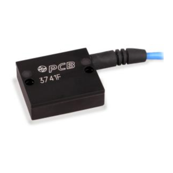
Model 3741F1210G
Differential MEMS DC accelerometer, 270 mV/g, 10 g, 10 ft integral cable
Installation and Operating Manual
For assistance with the operation of this product,
contact the PCB Piezotronics, Inc.
Toll-free: 716-684-0001
24-hour SensorLine: 716-684-0001
Fax: 716-684-0987
E-mail: info@pcb.com
Web: www.pcb.com
Advertisement
Table of Contents

Related Manuals for PCB Piezotronics 3741F1210G


Summary of Contents for PCB Piezotronics 3741F1210G
- Page 1 Model 3741F1210G Differential MEMS DC accelerometer, 270 mV/g, 10 g, 10 ft integral cable Installation and Operating Manual For assistance with the operation of this product, contact the PCB Piezotronics, Inc. Toll-free: 716-684-0001 24-hour SensorLine: 716-684-0001 Fax: 716-684-0987 E-mail: info@pcb.com...
-
Page 2: Repair And Maintenance
Assistance is needed to safely operate equipment PCB Piezotronics is an ISO-9001 certified company whose Damage is visible or suspected calibration services are accredited by A2LA to ISO/IEC Equipment fails or malfunctions 17025, with full traceability to SI through N.I.S.T. - Page 3 CAUTION Refers to hazards that could damage the instrument. NOTE Indicates tips, recommendations and important information. The notes simplify processes and contain additional information on particular operating steps. The following symbols may be found on the equipment described in this manual: This symbol on the unit indicates that high voltage may be present.
- Page 4 PCB工业监视和测量设备 - 中国RoHS2公布表 PCB Industrial Monitoring and Measuring Equipment - China RoHS 2 Disclosure Table 有害物质 镉 汞 铅 (Pb) 六价铬 (Cr(VI)) 多溴联苯 (PBB) 多溴二苯醚 (PBDE) 部件名称 (Hg) (Cd) 住房 PCB板 电气连接器 压电晶体 环氧 铁氟龙 电子 厚膜基板 电线 电缆 塑料 焊接...
- Page 5 Component Name Hazardous Substances Lead (Pb) Mercury (Hg) Cadmium (Cd) Chromium VI Polybrominated Polybrominated Compounds Biphenyls (PBB) Diphenyl Ethers (Cr(VI)) (PBDE) Housing PCB Board Electrical Connectors Piezoelectric Crystals Epoxy Teflon Electronics Thick Film Substrate Wires Cables Plastic Solder Copper Alloy/Brass This table is prepared in accordance with the provisions of SJ/T 11364.
- Page 6 General OPERATING GUIDE for use with High Sensitivity DC ACCELEROMETERS SPECIFICATION SHEET, INSTALLATION DRAWING AND CALIBRATION INFORMATION ENCLOSED PCB ASSUMES NO RESPONSIBILITY FOR DAMAGE CAUSED TO THIS PRODUCT AS A RESULT OF PROCEDURES THAT ARE INCONSISTENT WITH THIS OPERATING GUIDE. 1.0 INTRODUCTION Congratulations on the purchase of a quality, DC Lower range, higher sensitivity DC accelerometers, allow...
-
Page 7: Screw Mount
PCB’s High Sensitivity DC accelerometers are designed condition for operation, bridge conditioning equipment utilizing a MEMS typically has ZMO adjustment capability and standard (Micro-Electro-Mechanical Systems) connector accessories included which provide a “plug & silicon sensor approach. The micro machining design play”... -
Page 8: Adhesive Mount
A precision-machined mounting surface with a minimum finish of 32 in (0.0008 mm) is recommended. (If, and STEP 1: Prepare a smooth, flat mounting surface. A minimum surface finish of 32 in (0.0008 mm) generally only if, it is not possible to properly prepare the test structure mounting surface, consider adhesive mounting as works best. - Page 9 One cable type cannot satisfy all applications. Industrial 4.2-1 ADHESIVE MOUNT REMOVAL applications often require shielded, twisted-pair cables to (other than wax) reduce the effects of EMI and RFI that is present near Caution: It is usually difficult or near impossible to electrical motors and machinery.
-
Page 10: Accelerometer Calibration
STEP 4: Finally, connect the remaining cable end to the signal conditioner. 6.0 Signal Conditioning For optimum performance and flexibility, high sensitivity DC accelerometers benefit from a good stable, low noise dc power supply for excitation (Fig. 6). It should be regulated and stable to within 0.1% or better. -
Page 11: Recalibration Service
For these reasons, it is recommended that a recalibration cycle be established for each accelerometer. This schedule is unique and is based on a variety of factors, such as: extent of use, environmental conditions, accuracy requirements, trend information obtained from previous calibration records, contractual regulations, frequency of “cross- Figure 9. -
Page 12: Common Mistakes
Since the Back-to-Back Calibration technique relies on For stud-mount sensors, always mount the accelerometer each sensor experiencing an identical acceleration level, directly to the reference standard. Ensure that the mounting proper mounting of the test sensor to the reference surfaces are smooth, flat, and free of any burrs. Always use a standard is imperative. - Page 13 PCB®, ICP®, Swiveler®, Modally Tuned®, and IMI® with associated logo are registered trademarks of PCB Piezotronics, Inc. in the United States. ICP® is a registered trademark of PCB Piezotronics Europe GmbH in Germany and other countries. UHT-12™ is a trademark of PCB Piezotronics, Inc. SensorLine℠ is a service mark of PCB Piezotronics.
- Page 14 Model Number Revision: B DC RESPONSE ACCELEROMETER 3741F1210G ECN #: 53791 OPTION AL VERSION S Performance EN GLISH Optional versions have identical specifications and accessories as listed for the standard model except Sensitivity(± 3 %) 270 mV/g 27.5 mV/(m/s²) where noted below. More than one option may be used.
- Page 15 PCB Piezotronics Inc. claims proprietary rights in REVISIONS the information disclosed hereon. Neither it nor any reproduction thereof will be disclosed to others DESCRIPTION without the written consent of PCB Piezotronics Inc. CABLE ADD SENSING AXIS 51175 TERMINATE TO PIGTAIL ...
- Page 16 REVISIONS the information disclosed hereon. Neither it nor any reproduction thereof will be disclosed to others DESCRIPTION without the written consent of PCB Piezotronics Inc. -SEE SHEET 1- "SERVICE LOOP" TO ALLOW TYPE, PETRO WAX OR MOTION WITHOUT PULLING CABLE...
Need help?
Do you have a question about the 3741F1210G and is the answer not in the manual?
Questions and answers