
Subscribe to Our Youtube Channel
Related Manuals for Beghelli LOGICA SUPERVISOR 12131C

Summary of Contents for Beghelli LOGICA SUPERVISOR 12131C
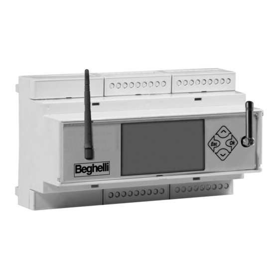
- Page 1 LOGICA SUPERVISOR CONTROL UNIT code 12131C Supervisor Control Unit for the centralised management and control of normal and emergency lighting systems INSTALLATION AND OPERATING INSTRUCTIONS...
-
Page 2: Table Of Contents
TABLE OF CONTENTS • WHAT IS THE SUPERVISOR CONTROL UNIT BY BEGHELLI pag. 3 • FUNCTIONS pag. 3 System monitoring pag. 3 System Control pag. 3 Keeping a Logbook pag. 3 • INSTALLATION pag. 4 RS 485 line use and termination pag. -
Page 3: What Is The Supervisor Control Unit By Beghelli
It controls and supervises up to 31 Logica Control Units by Beghelli via a RS485 bus (control unit code 12100C), and each control unit, in its turn, can handle up to 128 normal and emergency luminaires on a DALI bus, according to IEC60929. -
Page 4: Installation
INSTALLATION Use the layout below for reference to connect the Supervisor Control Unit to Logica Control Units (RS485 bus) and, if applicable, to the printer (RS232 bus) The connection to the system, via the LogicaVisual software, can be made via RS485_A and ETHERNET (starting from firmware version 1.20) Personal Computer... - Page 5 INPUT: for the connection of buttons, switches, outputs of other technological systems (e.g. anti- theft). Dry contact. OUTPUT: open collector output. Vmax 24V; Imax 50mA...
-
Page 6: Rs 485 Line Use And Termination
RS 485 LINE USE AND TERMINATION The Control Unit is equipped with 2 separate RS 485 lines (RS485_A and RS485_B); impedance adjustment possible on both lines by adding 2 2.54 pitch jumpers. Impedance adjustment is needed when the Control Unit is the "terminal" part of BUS 485 (the beginning or the end of the path). -
Page 7: Date And Time Settings
DATE AND TIME SETTINGS SAB 00:00:01 At the first start up, the system displays the LIGHTS menu: LIGHTS SAB 00:00:01 MAINTENANCE Maintenance MANUAL TEST Press the keys shown on the right in sequence to go Maintenance to the menu for time setting: SOFTWARE UPGRADE Maintenance CTRL UNIT MGT. -
Page 8: Searching For Logica Control Units (New Configuration)
Supervisor Control Unit; to set an address for a Logica Control Unit, refer to the “Logica Control Unit by Beghelli” manual. N.B.: also check that the system configuration command has been executed on all Logica Control Units installed and wired to the Supervisor Control Unit (see the “Logica Control Unit by... -
Page 9: Scheduling Functional And Autonomy Tests
Press to launch the search for Control Units. During the search, the two numbers shown on screen, divided by a Ctrl Unit Config. dash, mean: in progress - on the left: total number of Control Units detected up 000-000 to that moment - on the right: address of the Logica Control Unit under- going checks to see if it is connected to the system. -
Page 10: Groups
Supervisor Control Unit on a group, will affect the corresponding group of each Logica Control Unit by Beghelli in the system; if a command is sent to group '1' from the Supervisor Control Unit by Beghelli, that command will affect all luminaires belonging to group... -
Page 11: Menu
MENU The system is organised in menus that allow you to access varied features of the system: turn luminaires on and off, perform Functional and Autonomy Tests, review information on mal- functions, etc... To understand how to navigate among screens using the keys, see section “Keyboard and Display Functions”. -
Page 12: Maintenance Menu
MAINTENANCE MENU MANUAL TEST The Functional and Autonomy Tests are meant to check the emergency luminaires. Functional Tests consist in turning on the luminaire for about 30 seconds and checking the luminaire tube and battery efficiency; Autonomy Tests consist in turning on the luminaire for extended periods of time and checking if the battery is still working. -
Page 13: Emergency
ERROR STATUS This menu allows you to review and clear luminaire faults. If there is no error on any of the Logica Control Units by Beghelli connected to the Supervisor Control Unit by Beghelli, this menu will show: Error Status... -
Page 14: Control Unit Management
TEST MANAGEMENT This menu allows you to set, either individually for each Control Unit, or globally, for all Control Units: - Date and time of the next Functional Test; - Date and time of the next Autonomy Test; - Time interval between repeated Functional Tests - Time interval between repeated Autonomy Tests For test date, time and test scheduling, see section "Scheduling Functional and Autonomy Tests". -
Page 15: Print/Save
N.B.: printing will be available if the Supervisor Control Unit is connected to a Logica Din RS232 serial printer by Beghelli (code 12099). As an alternative, the data can be stored in files on a USB flash drive that can be connected to port USB1. This menu is available if the PRINTER/USB option has been selected in the previous menu. -
Page 16: Out. Err. On/Off
Out. Err. On/off The user can enable or disable the use of an auxiliary output, OUT2, to signal errors in the system or Tests in progress. Out.Test/Errors The auxiliary output is activated during Tests or when there are errors in the system. St. -
Page 17: Remote Configuration
FIGURATION", which is available on the Logica Control Units. The Logica Control Unit by Beghelli to which such a command is sent will perform a search for connected luminaires; the operation generally takes less than a minute. Within another minute or so, the Logica Control Unit will send to the Supervisor Control Unit all the information related to detected luminaires. -
Page 18: Technical Characteristics
TECHNICAL CHARACTERISTICS Code 21131C - Power supply voltage: 230V~50Hz - Max. input power: 12VA - Degree of protection IP20 - Insulation class II (double insulation ensured by installation inside protected cabinets that can be accessed with the use of a special tool, only by authorised service staff, for installation and maintenance purposes) - Operating ambient air temperature: 0°C +50°C - Housing: plastic case on 9-module DIN rail... - Page 20 . b e g h e l l i . c o m BEGHELLI S.p.A. - Via Mozzeghine 13/15 - località Monteveglio 40053 Valsamoggia (BO) - ITALY Phone +39 051 9660411 - Fax +39 051 9660444...
Need help?
Do you have a question about the LOGICA SUPERVISOR 12131C and is the answer not in the manual?
Questions and answers