Table of Contents
Advertisement
Quick Links
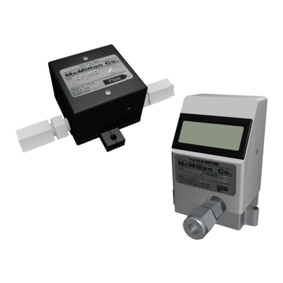
FLO-METERS
Installation Manual & Operating Instructions
READ THIS MANUAL COMPLETELY BEFORE ATTEMPTING TO CONNECT OR
OPERATE YOUR FLO-SENSOR. FAILURE TO DO SO MAY RESULT IN INJURY
©
C O P Y R I G H T
MODEL 100
MODEL 110
MODEL S-110
MODEL S-113
®
and FLO-SENSORS
TO YOU OR DAMAGE TO THE FLO-SENSOR.
.
2 0 0 7
R . D .
M C M I L L A N
Manual 100-M004
July 2007
Revision 4
www.mcmflow.com
®
For Gases
C O M P A N Y ,
I N C
Advertisement
Table of Contents

Related Manuals for McMillan FLO-SENSOR 100


Summary of Contents for McMillan FLO-SENSOR 100
- Page 1 Manual 100-M004 July 2007 Revision 4 www.mcmflow.com MODEL 100 MODEL 110 MODEL S-110 MODEL S-113 FLO-METERS ® and FLO-SENSORS ® For Gases Installation Manual & Operating Instructions READ THIS MANUAL COMPLETELY BEFORE ATTEMPTING TO CONNECT OR OPERATE YOUR FLO-SENSOR. FAILURE TO DO SO MAY RESULT IN INJURY TO YOU OR DAMAGE TO THE FLO-SENSOR.
-
Page 2: Table Of Contents
2. Cleaning and Flushing...............17 3. Returning Units For Repair Or Recalibration .........17 Part Number Information ...............19 Accessories...................20 Specifications ................21 Connector Pin and Wire Color Cross Reference .......22 Dimensions ..................23 Limited Warranty................30 Trouble Shooting Guide..............33 Contacting McMillan ..............35 100-M004, pg. 2 of 36... -
Page 3: Introduction
Introduction Unpacking McMillan suitably packages all sensors to prevent damage during shipping. If external damage is noted upon receipt of the package, please contact the shipping company immediately. McMillan Company is not liable for damage to the device once it has left the manufacturing premises. -
Page 4: Non-Standard Products (Z Suffixes)
Installation Caution: Do not exceed the pressure, temperature or power operating ranges detailed in the SPECIFICATIONS section of this manual. McMillan Company shall not be liable for any damage or injury caused by incorrect operation of their products. 100-M004, pg. 4 of 36... -
Page 5: General Considerations
This is the same position that the unit is calibrated in at the factory. Please contact the McMillan Service Department if calibration for mounting in another orientation is desired. -
Page 6: Tubing Connections
Only use the factory installed fittings on the unit. If the fittings are removed the calibration of the unit may be effected and leaking may occur. If different fittings are required please contact the McMillan Company Service Department for assistance. -
Page 7: Electrical Connections
Read the following instructions carefully before making any connections. Overview ® McMillan FLO-SENSORS for gases provide a 0-5VDC output proportional to the volumetric flow rate. This output may be connected to a display, data acquisition system or voltmeter. The Model 110, S-110 and S-113 ®... -
Page 8: B) Connecting A Cable Assembly
Connecting wires should be as short as possible to avoid voltage drops. Twisted 2 pair conductor cable of a suitable gauge should be used if the length of the power wires is to be longer than 1 meter (3.2 feet). Units are supplied with an integral 4 pin connector. -
Page 9: C) Electrical Connections - Voltage Output Units
Electrical Connections – Voltage Output Units The cable assembly should be connected to the sensor as detailed in section 5(b) above. Do not apply power to the sensor until all the connections have been made and checked. Electrical connections should be made as follows: Wiring Schematic For Voltage Output Units. -
Page 10: D) Using A 0-5Vdc Output Power Adapter Package
Using a 0-5VDC Output Power Adapter Package. An optional 0-5VDC Output Power Adapter Package is available for use with the Model 100, S-110 and S-113. The Model 110 is supplied complete with a 0-5VDC Output Power Adapter Package. The 0-5VDC Output Power Adapter Package consists of a power source (115VAC or 230VAC) and cable assembly with pig-tail (soldered wire) ends for the signal output. -
Page 11: E) Using A 4-20Ma Output Signal Converter Package (D-24Vdc)
Using a 4-20mA Output Signal Converter Package (D-24 VDC). An optional 4-20mA Output Signal Converter Package is available for use with the Model 100, S-110 and S-113. This consists of a signal converter, a cable assembly to connect the converter to the sensor and a cable assembly to connect to the 4-20mA (active current) output signal. -
Page 12: Operation
Before applying power to the unit check all tubing and electrical connections. Once correct installation is verified switch on the power. Flow Readings ® The McMillan Model 100 FLO-SENSOR for gases provides a 0-5VDC output proportional to the volumetric flow rate. ®... -
Page 13: B) 4-20Ma Outputs (Using The 4-20Ma Signal Converter)
For example: For a flow range of 100-500ml/min (Range 5) : At 500ml/min the output signal would be 5VDC If the output signal were 3.5VDC then the flow rate would be: (500 ÷ 5) × 3.5 = 350ml/min If the maximum flow rate is exceeded non-linear and inaccurate readings will result. -
Page 14: Operating At Flow Rates Outside The Calibrated Flow Range
LCD Flow Display (Model S-114 shown, other S Series models similar) Operating at Flow Rates Outside the Calibrated Flow Range CAUTION:. If the flow through the unit exceeds 120% of the maximum rated (full scale) flow the unit may be damaged. -
Page 15: Zero Adjustments
Zero Adjustments It is impossible for there to be any zero drift so zero adjustments are never required. Recalibration ® Please contact the McMillan Service Department if your FLO-SENSOR ® FLO-METER needs recalibration. ® ® Using FLO-SENSORS or FLO-METERS with Different Gases ®... - Page 16 CAUTION:. The use of correction factors can be subject to inaccuracy and errors of up to ±10%. Please contact the McMillan Service Department if accurate, certified recalibration is required. Calculating a correction factor for a gas enables the calibration of the unit to be adjusted for that gas.
-
Page 17: Maintenance And Product Care
Returning Units for Repair or Recalibration To return a unit for repair or recalibration please contact the McMillan Service Department or follow the procedure detailed on the McMillan web site. A Return to Manufacturer Authorization (RMA) number will then be issued to enable the unit to be returned. - Page 18 Mailing address: McMillan Company P.O. Box 1340 Georgetown, TX 78627 U.S.A. Phone: U.S.A. (512) 863-0231 Fax: U.S.A. (512) 863-0671 Email: tech@mcmflow.com Website: www.mcmflow.com 100-M004, pg. 18 of 36...
-
Page 19: Part Number Information
Part Number Information DESCRIPTION CODE ® Model 100 FLO-SENSOR ® Model 110 FLO-METER ® Model S-110 FLO-METER S-110 ® Model S-113 FLO-METER S-113 Flow Range (ml/min of AIR) 20-100 ml/min 40-200 ml/min 100-500 ml/min 200-1000 ml/min 0.4-2.0 l/min 1.0-5.0 l/min 2.0-10.0 l/min 4.0-20.0 l/min 10.0-50.0 l/min... -
Page 20: Accessories
Accessories DESCRIPTION CODE Cables and Power Adapters (Ordered Separately, Recommended For Operation) 100-17 4-pin Mating Cable with Pigtail Leads, 36” (92 cm) length 3 wire, 12/24VDC Power Required 100-17T 4-pin Mating Cable with Pigtail Leads, 36” (92 cm) length 4 wire, 12/24VDC Power Required S-PS-08 110VAC Power Adapter Package, 0-5VDC Output For 12VDC Models with 0-5VDC output... -
Page 21: Specifications
Specifications Model 100 Model 110 Model S-110 Model S-113 Display None 3.5 Digit LCD, 0.39” (10mm) high digits Accuracy ±3.0% Full Scale* (including linearity) Repeatability ±0.5% Full Scale* Pressure Rating 40 psig (2.8 bar) Temperature Rating Operating Range: 5 to 55ºC Storage Range: 0 to 70ºC Temperature ±0.2% F.S.* or less per ºC... -
Page 22: Connector Pin And Wire Color Cross Reference
Connector Pin And Wire Color Cross Reference Pin Configuration for Connector Socket and Connector Cable Wire Color Description Black Signal & Power Negative (Ground) White Voltage Output Power Positive Green Not Used 100-M004, pg. 22 of 36... -
Page 23: Dimensions
Dimensions ALL DIMENSIONS IN INCHES (MILLIMETERS IN BRACKETS) Model 100 - Flow Ranges 3-8, “A4” Fittings Shown 100-M004, pg. 23 of 36... - Page 24 Model 100- Flow Range 9, “A4” Fittings Shown 100-M004, pg. 24 of 36...
- Page 25 Model 100 - Flow Ranges 10-14, “A7” Fittings Shown 100-M004, pg. 25 of 36...
- Page 26 Model S-110 - Flow Ranges 3-8, “A4” Fittings Shown 100-M004, pg. 26 of 36...
- Page 27 Model S-110 - Flow Range 9, “A4” Fittings Shown 100-M004, pg. 27 of 36...
- Page 28 Model S-110 - Flow Ranges 10-14, “A7” Fittings Shown 100-M004, pg. 28 of 36...
- Page 29 Model S-113 - Flow Ranges 3-9, “A4” Fittings Shown 100-M004, pg. 29 of 36...
-
Page 30: Limited Warranty
Replacement parts are warranted to be free from defects in material or workmanship for ninety (90) days or for the remainder of the Limited Warranty period of the McMillan product in which they are installed, whichever is longer. Parts not installed by factory authorized service centers may void the warranty. - Page 31 If customer’s product fails to work as warranted herein, customer’s sole and exclusive remedy shall be the repair or replacement at McMillan’s option. McMillan is not liable for any damages caused by the product or the failure of the product to perform, including any lost profits or savings, incidental or consequential damages.
- Page 32 The arbitration shall be conducted in English. The UN Convention on Contracts for the International Sale of Goods shall not apply to this Limited Warranty. R. D. McMillan Company, Inc. 7075 R.R. 2338 P. O. Box 1340 Georgetown, Texas U.S.A.
-
Page 33: Troubleshooting Guide
Troubleshooting Guide Symptom Possible Cause Method of Correction Unit Leaks Fittings not tight enough. Tighten fittings (see section Sensor assembly cracked Unit must be returned for repair (see Section J) No output signal or No power or low power Apply correct power flow indication No flow passing through Display or output should... - Page 34 Symptom Possible Cause Method of Correction Flow indication is not Attempting to measure Use higher flow rates linear and output too flows below the specified low at lower flows minimum for the unit Moisture or liquid in sensor Remove moisture and allow sensor to dry out Mechanical sensor assembly Unit must be returned for...
-
Page 35: Contacting Mcmillan
Contacting McMillan Website: www.mcmflow.com Email: tech@mcmflow.com Mailing address: McMillan Company P.O. Box 1340 Georgetown, TX 78627 U.S.A. Shipping address: McMillan Company 7075 RR 2338 Georgetown, TX 78628 U.S.A. Phone: (512) 863-0231 Fax: (512) 863-0671 For repairs and/or return information, please contact our service department any of the ways shown above. - Page 36 THIS PAGE INTENTIONALLY LEFT BLANK. Manual 100-M004 July 2007 Revision 4 www.mcmflow.com 100-M004, pg. 36 of 36...
Need help?
Do you have a question about the FLO-SENSOR 100 and is the answer not in the manual?
Questions and answers