Table of Contents
Advertisement
Quick Links
Advertisement
Table of Contents

Related Manuals for IMS NANO easy


Summary of Contents for IMS NANO easy
- Page 3 Information of the device Designation: NANOeasy Manufacturer: IMS Robotics GmbH Am Bauhof 6 D-01458 Ottendorf-Okrilla, Germany Phone: +49 35205 75550 Fax: +49 35205 53749 Email: info@ims-robotics.de Website: www.ims-robotics.de User information: Version 13.08.2021 Translation of the original instruction Article number: 041 02 000 / 041 03 000...
- Page 4 Warranty terms All information and instructions for the operation and maintenance of the IMS NANOeasy cutter take into consideration our experience and technical expertise to date to the best of our knowledge. We reserve the right to make technical modifications within the context of further development of the device described in this operating manual.
-
Page 5: Table Of Contents
Cleaning ........................26 Care and maintenance ....................26 Repairs ..........................27 Repair of air motor IMS cutter NANOeasy ............. 27 6.1.1 Overview of air motor spare parts NANOeasy ............ 27 6.1.2 Disassembly of NANOeasy air motor and reassembly ........28 Way-valves ....................... -
Page 6: Intended Use
The IMS cutter NANOeasy must only be used for cutting work for the restoration of pressureless pipes or lines. The device can be used to open inliners after restoration and remove obstacles (roots, protruding seals, minor offsets, or the like). -
Page 7: Safety Regulations
No attempt should be made to reach between the bladder and the pipe wall while the bracing bladders are being inflated. The IMS NANOeasy cutter must not be operated outdoors without the auxiliary pipe. The bracing bladder must also not be located in front of an open... -
Page 8: Explanation Of Symbols And Notes
The air-powered cutter motor may be operated only while using hearing protection. Before moving the chassis you must always make sure that the locking pins for the handle section have properly engaged. 2.3 Explanation of symbols and notes The accident prevention regulations as well as the general and special safety stipulations must be observed when operating the unit. -
Page 9: Technical Data And Specifications For The Machine
3 Technical data and specifications for the machine Name: NANOeasy Item number: 041 02 000/041 03 000 Main dimensions: 1030 × 775 × 500 mm (W × D × H) Weight: approx. 35 kg Applications: Pipes with nominal diameters from 70 mm to 100 mm (inside diameter) Protection class: IP 54 (protected against access by small tools/wires and... -
Page 10: Operation
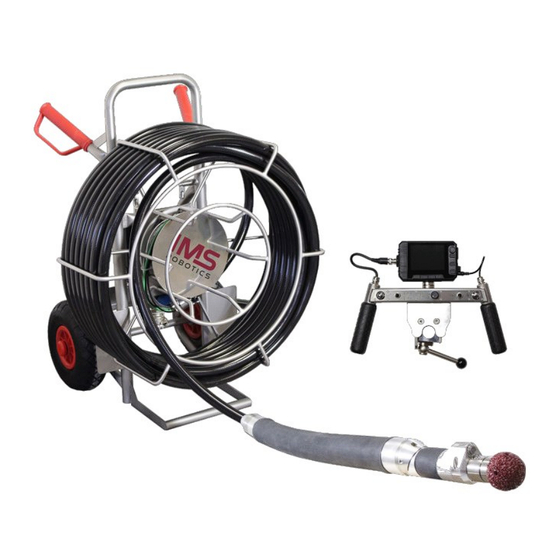
The device can be used to open inliners after renovation and remove obstacles (roots, protruding seals, minor offsets or the like). To start up the IMS NANOeasy cutter first set up the cutter itself and the necessary media. The cutter consists of the following assemblies:... - Page 12 The device serial number is located on the chassis. All assemblies have a minimum protection class of IP 54. This means that the assemblies are protected against: Penetration of wires Dust surrounding splash water The media must have the following properties: Power supply: 100 –...
-
Page 13: Extension Dn 150 For Nanoeasy (Optional)
4.2 Extension DN 150 for NANOeasy (optional) Due to an additional extension, the IMS cutter NANOeasy can be used in the nominal diameter range of more than 100 mm up to 150 mm. For this, the extension has to be pushed over the cutter drive from the cutting tool side and fastened to the crimp sleeve of the cutter drive by means of 4 set screws M4x6. -
Page 14: Start-Up
4.3 Start-up Attentively read these operating instructions Check the assemblies and accessories for completeness, and the media for the required qualities Transport the chassis to the desired work location (shaft, inspection opening or the like). Place the chassis in horizontal position. This is also the required working position for the chassis, since the water separator will otherwise not work correctly. - Page 15 The cable drum features an analogue and digital video output. Choosing between analogue and digital video signal can be done with the changeover switch. Attention! The analogue and digital video signal cannot be used simultaneously. When switching to the digital video signal, neither the analogue video socket nor the monitor on the control wheel can be used! Analogue video output Changeover switch analogue/digital video signal...
- Page 16 Connecting the monitor to the control wheel BNC video connection Monitor power supply Connect the cutter to the electrical supply; the LED (green) on the power supply unit must light; otherwise the power supply assembly is defective (replacement required) The camera light must be on Connect the supply line from the compressor to the coupling disc on the stand Insert the cutter drive into an auxiliary tube (approx.
- Page 17 Operating the device without an auxiliary pipe may irreparably damage the bracing bladder! All switches on the control wheel must be in the “Off” or “Stop” position. Switch the compressor ON Put on/insert ear protectors Switch on the air motor and check the function of the cutter motor Switch off the air motor.
-
Page 18: Control Wheel Nanoeasy
4.3.1 Control wheel NANOeasy BNC video port Connection cable control wheel to cable drum Lift the lifting unit Bracing bladder Bracing/Stop/Relief Supply hose clamping fixture Light camera potentiometer Cutter motor On/Off Lower lifting unit Internal power supply for monitor Monitor... -
Page 19: Operation During Work
4.4 Operation during work 4.4.1 Operating the IMS cutter NANOeasy Carefully insert the cutter drive into the pipe Push the cutter drive to the work location; when sliding through bends, turn the cutter head in the direction of curvature by rotating the supply hose and then deflect the lifting unit so that the bend can be pushed through without using force;... - Page 20 In such cases the lifting unit and the bracing bladder need to be emptied manually. This is realised using direction valve 1 and directional valve 2. The directional valve are marked accordingly. Directional valve 2 (bracing bladder) Directional valve 1 (lifting unit) The directional valves are located inside the cable drum.
- Page 21 To drain the lifting unit, detach the black 4 mm hose coming from the hose assembly at the adapter piece of the directional valve 1 (WV1). To this end, press the retaining ring of the adapter piece on the directional valve (WV 1) and pull out the hose. Air escapes from the lifting unit.
-
Page 22: Finishing Work
4.5 Finishing work Position the stroke drive upright Once the bracing bladder is completely relieved, pull out the cutter drive with supply hose from the pipe Insert the cutter drive into the auxiliary tube Allow the air motor and tool to run on for approx. 20 seconds in order to blow out the residual water from the cutter motor Switch the compressor OFF (prior to switching the air motor OFF so that the cutter is completely depressurized!) - Page 23 Store chassis with hose assembly and cutter drive securely in the vehicle; do not kink the bracing and lifting bladder of the cutter drive Stow the control wheel and accessories Secure the complete cutter during transport...
-
Page 24: Cutter Tools
Original IMS cutter tools meet the requirements in terms of quality, stability and true running, and especially in terms of design-engineered properties. -
Page 25: Changing The Nanoeasy Cutter Tool
4.6.2 Changing the NANOeasy cutter tool The two pins (3 × 30) supplied are used to remove the cutter tool. The rotor is fixed by setting one pin into the prescribed bore hole (1) on the housing. The pin must engage in the hole of the rotor. -
Page 26: Maintenance And Repair
5.2 Care and maintenance Regular inspection of the media supply lines to the IMS cutter NANOeasy and to the control wheel as well as the visual check of the hose package is stipulated. Damaged or kinked hoses lead to admission of water into the cutter and thus to damage of electrical components as well as corrosion of mechanical parts. -
Page 27: Repairs
6 Repairs 6.1 Repair of air motor IMS cutter NANOeasy 6.1.1 Overview of air motor spare parts NANOeasy 040 01 017 Ball bearing 040 01 014 Vent ring 040 01 011 Cylinder 006 40 001 Ball bearing with adjusting washer and circlip... -
Page 28: Disassembly Of Nanoeasy Air Motor And Reassembly
6.1.2 Disassembly of NANOeasy air motor and reassembly Unscrew the cutter tool (see 4.6.2 Changing the NANOeasy cutter tool). Unscrew air motor cover clockwise (Attention, left-handed thread!) with face spanner. Remove straight pin and pull out air motor. Replace discs and reassemble air motor in reverse order. - Page 29 To change the front bearing place the rotor with bearing between two aluminium blocks and carefully knock out rotor using a plastic mallet. A new bearing can now be inserted. Fix the ball bearing in place. Then knock down rotor against the stop. Slide up vent ring so that the shoulder points toward the bearing.
-
Page 30: Way-Valves
6.2 Way-valves The directional valves (WV 1 – 2 and WV 3) are spare parts and can be ordered from IMS (see point Fehler! Verweisquelle konnte nicht gefunden werden. Fehler! Verweisquelle konnte nicht gefunden werden.) 6.2.1 Overview of directional valve spare part 016 12 010 Directional (WV 1 –... -
Page 31: Replacing The Way-Valves
6.2.2 Replacing the way-valves 6.2.2.1 Replacing directional valves WV 1 – 2 (lift, bracing bladder) Directional valves 1 and 2 are located inside the cable drum. To get to the directional valves, first remove the cover plate in the centre of the cable drum using the 3 countersunk screws M4×8. -
Page 32: Replacing The Directional Valve Wv 3 (Cutter Air)
6.2.2.2 Replacing the directional valve WV 3 (cutter air) Directional valve 3 is located inside the cable drum. To get to the directional valves, first remove the cover plate in the centre of the cable drum using the 3 countersunk screws M4×8. - Page 33 plug. Replace the directional valve. Reconnect the hoses and plug. Mount the directional valve 3 and mounting plate. Attach directional valves 1 and 2 with screws to the mounting plate and installed the cover plate. Countersunk screws M4×30 Pull off the transparent 10 mm hoses Plug Unscrew plug...
-
Page 34: Ec Declaration Of Conformity
7 EC Declaration of Conformity... -
Page 35: Accessory Overview Nanoeasy
8 Accessory overview NANOeasy...
Need help?
Do you have a question about the NANO easy and is the answer not in the manual?
Questions and answers